Transcription
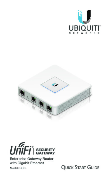
Ethernet Gateway Link150DOCA0110EN-02 05/2017Ethernet Gateway Link150User m
The information provided in this documentation contains general descriptions and/or technicalcharacteristics of the performance of the products contained herein. This documentation is not intended asa substitute for and is not to be used for determining suitability or reliability of these products for specificuser applications. It is the duty of any such user or integrator to perform the appropriate and complete riskanalysis, evaluation and testing of the products with respect to the relevant specific application or usethereof. Neither Schneider Electric nor any of its affiliates or subsidiaries shall be responsible or liable formisuse of the information contained herein. If you have any suggestions for improvements or amendmentsor have found errors in this publication, please notify us.No part of this document may be reproduced in any form or by any means, electronic or mechanical,including photocopying, without express written permission of Schneider Electric.All pertinent state, regional, and local safety regulations must be observed when installing and using thisproduct. For reasons of safety and to help ensure compliance with documented system data, only themanufacturer should perform repairs to components.When devices are used for applications with technical safety requirements, the relevant instructions mustbe followed.Failure to use Schneider Electric software or approved software with our hardware products may result ininjury, harm, or improper operating results.Failure to observe this information can result in injury or equipment damage. 2017 Schneider Electric. All Rights Reserved.2DOCA0110EN-02 05/2017
Table of ContentsSafety Information. . . . . . . . . . . . . . . . . . . . . . . . . . . . . . . . . . . . . . . . . . . .About the Book . . . . . . . . . . . . . . . . . . . . . . . . . . . . . . . . . . . . . . . . . . . . . .Chapter 1 Link150 Presentation . . . . . . . . . . . . . . . . . . . . . . . . . . . . . . . . . . . . . . . . .Ethernet Gateway Link150 Description . . . . . . . . . . . . . . . . . . . . . . . . . . . . . . . . . . . . . . . . .Hardware Description . . . . . . . . . . . . . . . . . . . . . . . . . . . . . . . . . . . . . . . . . . . . . . . . . . . . . .Ethernet Gateway Link150 Characteristics . . . . . . . . . . . . . . . . . . . . . . . . . . . . . . . . . . . . . .Ethernet Gateway Link150 Firmware Update . . . . . . . . . . . . . . . . . . . . . . . . . . . . . . . . . . . .Protecting the Environment . . . . . . . . . . . . . . . . . . . . . . . . . . . . . . . . . . . . . . . . . . . . . . . . . .Chapter 2 Link150 Web Server . . . . . . . . . . . . . . . . . . . . . . . . . . . . . . . . . . . . . . . . . .2.1 Ethernet Gateway Link150 . . . . . . . . . . . . . . . . . . . . . . . . . . . . . . . . . . . . . . . . . . . . . . . . . .Access to Link150 Webpages . . . . . . . . . . . . . . . . . . . . . . . . . . . . . . . . . . . . . . . . . . . . . . . .Link150 User Interface Layout. . . . . . . . . . . . . . . . . . . . . . . . . . . . . . . . . . . . . . . . . . . . . . . .Link150 Webpage Description. . . . . . . . . . . . . . . . . . . . . . . . . . . . . . . . . . . . . . . . . . . . . . . .2.2 Link150 Web Server - Configuration & Settings Pages . . . . . . . . . . . . . . . . . . . . . . . . . . . . .Device Location/Name . . . . . . . . . . . . . . . . . . . . . . . . . . . . . . . . . . . . . . . . . . . . . . . . . . . . .Device Name . . . . . . . . . . . . . . . . . . . . . . . . . . . . . . . . . . . . . . . . . . . . . . . . . . . . . . . . . . . . .Ethernet Configuration (Dual Port) . . . . . . . . . . . . . . . . . . . . . . . . . . . . . . . . . . . . . . . . . . . .IP Configuration . . . . . . . . . . . . . . . . . . . . . . . . . . . . . . . . . . . . . . . . . . . . . . . . . . . . . . . . . . .Advanced Ethernet Settings . . . . . . . . . . . . . . . . . . . . . . . . . . . . . . . . . . . . . . . . . . . . . . . . .Modbus TCP/IP Filtering . . . . . . . . . . . . . . . . . . . . . . . . . . . . . . . . . . . . . . . . . . . . . . . . . . . .Serial Port . . . . . . . . . . . . . . . . . . . . . . . . . . . . . . . . . . . . . . . . . . . . . . . . . . . . . . . . . . . . . . .Date and Time . . . . . . . . . . . . . . . . . . . . . . . . . . . . . . . . . . . . . . . . . . . . . . . . . . . . . . . . . . . .Device List . . . . . . . . . . . . . . . . . . . . . . . . . . . . . . . . . . . . . . . . . . . . . . . . . . . . . . . . . . . . . . .SNMP Parameters. . . . . . . . . . . . . . . . . . . . . . . . . . . . . . . . . . . . . . . . . . . . . . . . . . . . . . . . .Advanced Services Control . . . . . . . . . . . . . . . . . . . . . . . . . . . . . . . . . . . . . . . . . . . . . . . . . .User Accounts . . . . . . . . . . . . . . . . . . . . . . . . . . . . . . . . . . . . . . . . . . . . . . . . . . . . . . . . . . . .Webpage Access. . . . . . . . . . . . . . . . . . . . . . . . . . . . . . . . . . . . . . . . . . . . . . . . . . . . . . . . . .2.3 Link150 Web Server - Diagnostics Pages . . . . . . . . . . . . . . . . . . . . . . . . . . . . . . . . . . . . . . .Statistics for Modbus/TCP and ION Protocols. . . . . . . . . . . . . . . . . . . . . . . . . . . . . . . . . . . .Device Information. . . . . . . . . . . . . . . . . . . . . . . . . . . . . . . . . . . . . . . . . . . . . . . . . . . . . . . . .Read Device Registers . . . . . . . . . . . . . . . . . . . . . . . . . . . . . . . . . . . . . . . . . . . . . . . . . . . . .Chapter 3 Troubleshooting . . . . . . . . . . . . . . . . . . . . . . . . . . . . . . . . . . . . . . . . . . . . .Troubleshooting . . . . . . . . . . . . . . . . . . . . . . . . . . . . . . . . . . . . . . . . . . . . . . . . . . . . . . . . . . .DOCA0110EN-02 414243444546495051513
4DOCA0110EN-02 05/2017
Safety InformationImportant InformationNOTICERead these instructions carefully, and look at the equipment to become familiar with the device beforetrying to install, operate, or maintain it. The following special messages may appear throughout thisdocumentation or on the equipment to warn of potential hazards or to call attention to information thatclarifies or simplifies a procedure.PLEASE NOTEElectrical equipment should be installed, operated, serviced, and maintained only by qualified personnel.No responsibility is assumed by Schneider Electric for any consequences arising out of the use of thismaterial.A qualified person is one who has skills and knowledge related to the construction and operation ofelectrical equipment and its installation, and has received safety training to recognize and avoid thehazards involved.FCC NoticeThis equipment has been tested and found to comply with the limits for a Class A digital device, pursuantto part 15 of the FCC Rules. These limits are designated to provide reasonable protection against harmfulinterference when the equipment is operated in a commercial environment. This equipment generates,uses, and can radiate radio frequency energy and, if not installed and used in accordance with theinstruction manual, may cause harmful interference to radio communications. Operation of this equipmentin a residential area is likely to cause harmful interference in which case the user will be required to correctthe interference at this own expense.DOCA0110EN-02 05/20175
6DOCA0110EN-02 05/2017
About the BookAt a GlanceDocument ScopeThe aim of this document is to provide the users, installers, and maintenance personnel with the technicalinformation and procedures needed to access and maintain the Link150 web server.Validity NoteThe technical characteristics of the devices described in this document also appear online. To access thisinformation online:StepAction1Go to the Schneider Electric home page www.schneider-electric.com.2In the Search box type the reference of a product or the name of a product range. Do not include blank spaces in the reference or product range. To get information on grouping similar modules, use asterisks (*).3If you entered a reference, go to the Product Datasheets search results and click on thereference that interests you.If you entered the name of a product range, go to the Product Ranges search results and clickon the product range that interests you.4If more than one reference appears in the Products search results, click on the reference thatinterests you.5Depending on the size of your screen, you may need to scroll down to see the data sheet.6To save or print a data sheet as a .pdf file, click Download XXX product datasheet.The characteristics that are presented in this manual should be the same as those characteristics thatappear online. In line with our policy of constant improvement, we may revise content over time to improveclarity and accuracy. If you see a difference between the manual and online information, use the onlineinformation as your reference.Related DocumentsTitle of DocumentationReference NumberTSXETG100 ConneXium Ethernet Gateway User Guide63230-319-225 (EN, ES, FR, DE)EGX100 Ethernet Gateway User Guide63230-319-204 (EN, ES, FR, DE, ZH)Ethernet Gateway Link150 Instruction SheetNHA50221You can download these technical publications and other technical information from our website A0110EN-02 05/20177
8DOCA0110EN-02 05/2017
Ethernet Gateway Link150Link150 PresentationDOCA0110EN-02 05/2017Chapter 1Link150 PresentationLink150 PresentationWhat Is in This Chapter?This chapter contains the following topics:TopicDOCA0110EN-02 05/2017PageEthernet Gateway Link150 Description10Hardware Description11Ethernet Gateway Link150 Characteristics15Ethernet Gateway Link150 Firmware Update16Protecting the Environment199
Link150 PresentationEthernet Gateway Link150 DescriptionIntroductionThis manual is to be used with Ethernet Gateway Link150. For installation information, see the EthernetGateway Link150 Instruction Sheet.Ethernet Gateway Link150 is a communication device that provides connectivity between Ethernet(Modbus TCP/IP) and Modbus serial line devices, allowing Modbus TCP/IP clients to access informationfrom serial slave devices. It also allows serial master devices to access information from slave devicesdistributed across an Ethernet network.Ethernet Gateway Link150 FeaturesThe Ethernet Gateway Link150 supports the following Ethernet protocols: Modbus TCP/IP: Modbus TCP/IP is a protocol, which provides master/slave communication betweendevices and TCP/IP that provides communications over an Ethernet connection. Modbus TCP/IP isused to exchange data between Ethernet Gateway Link150 and other compatible Modbus TCP/IPdevices through TCP port 502. Hypertext Transfer Protocol (HTTP): HTTP is a network protocol that handles delivery of files and dataon the World Wide Web. It provides web server functionality through TCP port 80. Remote configurationof Ethernet Gateway Link150 and viewing of diagnostic data is possible using a web browser. File Transfer Protocol (FTP): FTP is a network protocol that provides the ability to transfer files over theInternet from one computer to another. FTP is used to transfer firmware updates to Ethernet GatewayLink150 through TCP port 21. Simple Network Management Protocol (SNMP): Based on MIB2 format, SNMP provides the ability tostore and send identifying and diagnostic information used for network management purposes throughUDP port 161. Address Resolution Protocol (ARP): ARP is used to convert IP addresses to Ethernet addresses. ARPrequests are sent by Ethernet Gateway Link150 to determine if its address is a duplicate IP address.10DOCA0110EN-02 05/2017
Link150 PresentationHardware DescriptionAB:C:D:E:F:G:H:I:J:K:L:M:N:ETH1: Ethernet 1 communication portETH2: Ethernet 2 (Power over Ethernet) communication port24 Vdc power supply terminal blockEthernet communication LEDsModule status LEDNetwork status LEDSealable transparent coverIP reset pinRS485 traffic status LEDDevice soft restart button (Accessible through closed cover)RS232 traffic status LEDDevice name labelRS232 portRS485 port24 Vdc Power Supply Terminal BlockEthernet Gateway Link150 is powered by 24 Vdc or Power-over-Ethernet (PoE). We recommend a ULlisted and UL recognized limited voltage/limited current or a Class 2 power supply with a 24 Vdc, 500 mAminimum.NOTE: When the module is connected with both PoE and 24 Vdc and if 24 Vdc is removed, there is atemporary communication loss until the device gets power from PoE.DOCA0110EN-02 05/201711
Link150 PresentationA:B:C:D:E:Ethernet 1 communication portEthernet 2 (PoE) communication portMidspan PoE injectorEthernet switch with Endspan PoE portsEthernet SwitchEthernet Communication LEDsEthernet dual color LEDs indicates the communication status of Ethernet ports ETH1 and ETH2.LED indicationStatus indicationYellow10 Mbps linkYellow blink10 Mbps activityGreen100 Mbps linkGreen blink100 Mbps activityModule Status LEDModule status dual color LED indicates the module status of Ethernet Gateway Link150.LED indicationStatus indicationSteady offNo powerSteady greenDevice operationalSteady redOut of serviceFlashing green (500 ms ON, 500 ms OFF)Firmware corruptedFlashing redDegraded modeFlashing green/red (250 ms green, 250 ms red)Self-testNOTE:If the IP reset pin is released after 5 seconds and before 10 seconds, the module status LED flashesgreen till the IP reset pin is released. If the IP reset pin is released after 15 seconds, the module status LED turns to steady green. Network Status LEDNetwork status dual color LED indicates the network status of Ethernet Gateway Link150.LED indicationStatus indicationOffNo power or no IP addressSteady greenValid IP addressSteady redDuplicated IP addressBlinking green/red (250 ms green, 250 ms red)Self test in progressSteady amberError in IP configuration or default IP addressRS232 Traffic LEDRS232 serial line traffic yellow LED indicates that the traffic is being transmitted or received over RS232serial line network through the Ethernet Gateway Link150. The LED blinks during the transmission andreception of the messages. Otherwise, the LED is OFF.12DOCA0110EN-02 05/2017
Link150 PresentationRS485 Traffic LEDRS485 serial line traffic yellow LED indicates that the traffic is being transmitted or received over RS485serial line network through the Ethernet gateway Link150. The LED blinks during the transmission andreception of the messages. Otherwise, the LED is OFF.IP Reset PinWhen the IP reset pin is pressed for 1 to 5 seconds, the IP acquisition mode is reset to the factory default(DHCP).Factory ResetWhen the IP reset pin is pressed for 10 to 15 seconds, all user-configurable information is reset to factorydefaults.Device Soft Restart ButtonPress the device soft restart button for 10 to 15 seconds to soft restart the Link150. For more details referto troubleshooting (see page 51) section.RS232 Connection DiagramABCRS232 serial portRJ45 to DB9RJ45 crossover cablePin NumberSignal NameDescription1DSRData Set Ready2DCDData Carrier Detect3DTRData Terminal Ready4GNDGround5RXReceive Data6TXTransmit Data7CTSClear to Send8RTSRequest to SendRS485 2-Wire Connection DiagramABDOCA0110EN-02 05/2017RS485 serial portRJ45 cable (VW3A8306D30 is an accessory for RJ45 connection)13
Link150 PresentationPin NumberSignal NameDescription1D1Data 2D0Data-3NCNo Connection4D1Data 5D0Data-6NCNo Connection7NCNo Connection8GNDGroundShieldShieldRS485 4-Wire Connection DiagramABRS485 serial portRJ45 cable (VW3A8306D30 is an accessory for RJ45 connection)Pin NumberSignal NameDescription1RX-Receive Data-2RX Receive Data 3NCNo Connection4TX Transmit Data 5TX-Transmit Data-6NCNo Connection7NCNo Connection8GNDGroundShieldShield14DOCA0110EN-02 05/2017
Link150 PresentationEthernet Gateway Link150 CharacteristicsEnvironmental CharacteristicsCharacteristicsValueConforming to standards IEC/UL 60950 AS/ZNS 60950 CSA C22.2 IEC/UL 61010-2-201 EN55024 EN55022 IEC61000-6-2 Ed.2Certification cULus, CE, RCM, and FCC markingAmbient temperatureStorage-40 to 85 C (-40 to 185 F)Operation-25 to 70 C (-13 to 158 F)PollutionLevel 2Mechanical CharacteristicsCharacteristicsValueShock resistanceConforming to IEC 60068-2-27 15 g/11 ms, 1/2 sinusoidalResistance to sinusoidal vibrationsConforming to IEC/EN 60068-2-6Electrical CharacteristicsCharacteristicsValue24 Vdc modePOE modePower Supply24 Vdc, -20%/ 10% (19.2 Vdc -26.4 VdcAs per IEEE 802.3af compliant24 Vdc, 130 mA at 20 C48 Vdc, 65 mA at 20 CConsumptionTypicalPhysical CharacteristicsCharacteristicsValueDimensions72 x 105 x 71 mm (2.83 x 4.13 x 2.79 in)MountingDIN railWeight175 g without packingDegree of protection of the installed module On the front panel (wall-mounted enclosure): IP4x Connectors: IP2x Other parts: IP3xConnections Screw type terminal block for 24 Vdc power RJ45 for communicationInstallation typeDOCA0110EN-02 05/2017Open type equipment15
Link150 PresentationEthernet Gateway Link150 Firmware UpdateDescriptionLink150 firmware consists of two types of components: The executable binary component The webpage and supporting file (Data file)The firmware on the Link150 can be updated using FTP.NOTE: The gateway.bin and exploit.bin files are incompatible.NOTICEHAZARD OF EQUIPMENT DAMAGEDo not upgrade the gateway.bin file in a system which has the exploit.bin file.Failure to follow these instructions can result in equipment damage.Upgrading the FirmwareStepAction1Check the firmware current version. Follow the steps given in Checking the Executable Binary Component Firmware Version(see page 16).2If the firmware version is 5.0.21 or later, follow the steps given in Standard Firmware Upgrade Process (Upgrade from Version5.0.21 or Later) (see page 16).3If the firmware version is 5.0.11 or earlier, follow the steps given in Special Instruction for Upgrade from Legacy Firmware (Version5.0.11 or Earlier) (see page 17).Checking the Executable Binary Component Firmware VersionStepActionResult1Open the web browser and log in to the Link150.Opens the Link150 home page.2From the Diagnostics menu, in the Device Information page, locate thefirmware version.Determines the firmware version of the Link150.NOTE: If you have updated the firmware recently, press F5 to refreshthe webpage and update the displayed firmware number.Standard Firmware Upgrade Process (Upgrade from Version 5.0.21 or Later)StepActionResult1Downloads the Link150 firmware file.Download the latest Link150 firmwareLink150FirmwareAndDataFilesVAAABBBCCC.zip file fromwww.schneider-electric.com (where AAABBBCCC is the datafile versionnumber).2Unzip Link150FirmwareAndDataFilesVAAABBBCCC.zip andstore it in your local PC.Stores the unzipped Link 150 firmware folders in thelocal PC.3Open the Link150FirmwareAndDataFilesVAAABBBCCC folder.Opens the Link 150 firmware foldergateway.bin to gateway.bin.4Right-click the FirmwareUpgrade.bat, and then click Edit.Opens FirmwareUpgrade.bat in a notepad format.5Set the IP address, FTP user name, and password of the module beingupgraded in the FirmwareUpgrade.bat file.The IP address, user name, and password are updatedin the FirmwareUpgrade.bat file.NOTE: Default IP address 169.254.YY.ZZ Default FTP user name Administrator Default FTP password Gateway (Make sure that theAdministrator password is not empty.)616Save and exit the FirmwareUpgrade.bat.The IP address, user name, and password are set in theFirmwareUpgrade.bat file.7Double-click the FirmwareUpgrade.bat file.The firmware and data file upgrade starts.8Wait until the FirmwareUpgrade.bat file closes itself.The firmware and data file upgrade is completed.DOCA0110EN-02 05/2017
Link150 PresentationNOTE: YY.ZZ are the last 2 bytes of the Link150 MAC address. For example, A Link150 with MAC address 00B0-D0-86-BB-F7 (hexadecimal) or 0-176-208-134-187-247 (decimal), set the IP address as169.254.187.247 in the batch file. For the Link150 with the MAC address 00-B0-D0-86-02-12 (hexadecimal) or 0-176-208-134-02-18(decimal), set the IP address as 169.254.2.18 in the batch file. After successful firmware upgrade, Link150 takes 40 seconds to restart.Special Instructions for Upgrade from Legacy Firmware (Version 5.0.11 or Earlier)StepActionResult1Download the latest Link150 firmwareLink150FirmwareAndDataFilesVAAABBBCCC.zip file fromwww.schneider-electric.com (where AAABBBCCC is the datafileversion number).Downloads the Link150 firmware file.2Unzip Link150FirmwareAndDataFilesVAAABBBCCC.zip andstore it in your local PC.Stores the unzipped Link 150 firmware folders in thelocal PC.3Open the Link150FirmwareAndDataFilesVAAABBBCCC folder.Opens the Link 150 firmware folderexploit.bin to gateway.bin.4Right-click the FirmwareUpgrade 1.bat, and then click Edit.Opens FirmwareUpgrade 1.bat in a notepadformat.5Set the IP address, FTP user name, and password of the module beingupgraded in the FirmwareUpgrade 1.bat file.The IP address, user name, and password are updatedin the FirmwareUpgrade 1.bat file.NOTE: Default IP address 169.254.YY.ZZ Default FTP user name Administrator Default FTP password Gateway (Make sure that theAdministrator password is not empty.)6Save and exit the FirmwareUpgrade 1.bat file.The IP address, user name, and password are set in theFirmwareUpgrade 1.bat file.7Double-click the FirmwareUpgrade 1.bat file.The firmware and data file upgrade starts.8Wait until the FirmwareUpgrade 1.bat file closes itself.The firmware and data file upgrade is partiallycompleted.NOTE: The device will reboot. This may take 30–40 seconds.9Repeat steps 4–8 for FirmwareUpgrade 2.bat file once the network The firmware and data file upgrade is completed.status of the device is up.NOTE:YY.ZZ are the last 2 bytes of the Link150 MAC address. For example, A Link150 with MAC address 00B0-D0-86-BB-F7 (hexadecimal) or 0-176-208-134-187-247 (decimal), set the IP address as169.254.187.247 in the batch file. For the Link150 with the MAC address 00-B0-D0-86-02-12 (hexadecimal) or 0-176-208-134-02-18(decimal), set the IP address as 169.254.2.18 in the batch file. After successful firmware upgrade Link150 takes 40 seconds to restart. It is mandatory to press the Factory Reset pin. For more details, refer to Factory Reset (see page 13). DOCA0110EN-02 05/201717
Link150 PresentationUpdating the Webpages and Device Supporting Files Using FTPStepActionResult1Start the web browser, type ftp:// device IP address in theAddress box, and then press Enter.Starts the FTP session and prompts for user name andpassword.2Type Administrator as the user name and Gateway as thepassword in the boxes, and then click Log On.Succeeds login process and locates the directorywwwroot.3Upgrade the webpage by: locate wwwroot directory. Except the folders, delete all the files inwwwroot directory. Drag and drop the new files from the wwwrootfolder of the newly saved Link150 DataFiles Vx.y.z file. locate logging/templates directory. Delete all the files inlogging/templates directory. Drag and drop the new files fromthe logging/templates folder of the newly savedLink150 DataFiles Vx.y.z file. Deletes the files from the directory except the folder.Restart the Link150.Updates the webpages and the device supporting files.4 Adds the new files from the PC to the directory. Updates the webpages and the device supportingfiles.NOTE: The device date and time will be set to default values after firmware upgrade.Updating the Gateway Application Using FTPStepActionResult1Start the web browser, type ftp:// device IP address in the Address box, and then press Enter.Starts the FTP session and prompts for user name andpassword.2Type Administrator as the user name and Gateway as the Succeeds the login process.password in the boxes, and then click Log On.3Double-click and switch to fw directory.Deletes the gateway file from the directory except the folder.NOTE: You can delete the gateway if it is already available inthe directory.184In your local PC, locate the latest version of firmware and then Link150 reboots and it runs with the new version of thecopy and paste it on the FTP client software or drag and drop it firmware.to the working directory.5Log out or close the FTP client software and close the FTPsession.Succeeds the logout process.DOCA0110EN-02 05/2017
Link150 PresentationProtecting the EnvironmentRecycling PackagingPacking materials from this equipment can be recycled. Help protect the environment by recycling them inappropriate containers.Thank you for doing your part in protecting the environment.End-of-Life RecyclingModules of Link150 system have been optimized to decrease the amount of waste and valorize the productcomponents and materials in the usual end of life treatment process.The product design allows components to enter the usual end of life treatment processes as appropriate: DepolluteReuse and/or dismantlingThis increases the recycling performance and allows the rest of materials to be separated by shredding.DOCA0110EN-02 05/201719
Link150 Presentation20DOCA0110EN-02 05/2017
Ethernet Gateway Link150Link150 Web ServerDOCA0110EN-02 05/2017Chapter 2Link150 Web ServerLink150 Web ServerWhat Is in This Chapter?This chapter contains the following sections:SectionDOCA0110EN-02 05/2017TopicPage2.1Ethernet Gateway Link150222.2Link150 Web Server - Configuration & Settings Pages292.3Link150 Web Server - Diagnostics Pages4521
Link150 Web ServerSection 2.1Ethernet Gateway Link150Ethernet Gateway Link150What Is in This Section?This section contains the following topics:TopicPageAccess to Link150 Webpages23Link150 User Interface Layout27Link150 Webpage Description2822DOCA0110EN-02 05/2017
Link150 Web ServerAccess to Link150 WebpagesSupported Web BrowsersBrowserVersion withWindows XPVersion with Windows VistaVersion with Windows 7Internet ExplorerIE 8.0IE 9.0IE 10.0Firefox15.020.020.0Chrome (recommended)24.0 and later24.0 and later24.0 and laterFirst Access to the Link150 WebpagesThe Link150 name should be configured during the first access to the Link150 webpages.The procedure to access the Link150 webpages for the first time depends on the operating system of acomputer: Windows Vista, Windows 7, or newer operating systems Windows XP or older operating systemsFirst Access Through PC with Windows 7, Windows Vista, or Newer Operating SystemsStepAction1Disconnect the PC from the local area network (LAN) and switch off Wi-Fi if any.2Connect an Ethernet cable from the computer to the Link150 or to the Ethernet switch inside the panel.NOTE: Perform this action when the device goes to fallback ip.3Open web browser.4Click Network and the Link150-XXYYZZ appears in the list of devices.NOTE: If the Link150-name is not displayed in the list of devices in Windows Explorer, verify that the PC Link150 are connectedthrough the router.5Double-click the selected Link150-XXYYZZ. The login page automatically opens in the browser.6Enter Administrator as the user name and Gateway as the password. The home page opens in the browser.7To locate the Link150-XXYYZZ, select the Configuration & Settings menu, go to Device Location/Name submenu, click Devicephysical location, and then click Blink ON.The RS485 LED of the selected Link150-XXYYZZ blinks for 15 seconds with 1 s ON and 1 s OFF (test mode).8To name the Link150-XXYYZZ, select the Configuration & Settings menu, go to Device Name submenu, click Device Name, go toDevice Name Configuration, and then enter Link150-XXYYZZ and click Apply to set the Link150 name.9Write the Link150 name on a blank device name label and stick it on the existing one.NOTE: The user name and password are case-sensitive.NOTE:Follow the preceding procedure when link150 goes to fallback IP due to duplicate IP detection or dueto any other case. XXYYZZ are the last 3 bytes of the MAC address in hexadecimal format. Check the firewall settings if DPWS is not enabled. DOCA0110EN-02 05/201723
Link150 Web ServerFirst Access Through PC with Windows XP or Older Operating SystemsStepAction1Disconnect your local computer from all networks (LAN) and switch off Wi-Fi if any.2Connect an Ethernet cable from the computer to the Link150.3Start Internet Explorer 8, Mozilla Firefox 15, Chrome 24 (or later versions).4In the address box, type 169.254.YY.ZZ, where YY and ZZ are the last 2 bytes of the Link150 MAC address (found onthe Link150 side label), and then press Enter. The home page opens in the browser.Example: For the Link150 with the MAC address 00-B0-D0-86-BB-F7 or 0-176-208-134-187-247 in decimal, type169.254.187.247 in the address box.NOTE: Perform this action when the device goes to fallback ip.NOTE: The computer automatically uses the default 169.254.#.# (# 0–255) and the default subnet mask 255.255.0.0.5Press Enter, the login page automatically opens in the browser.6Type Administrator as the user name and Gateway as the password. The homepage automatically opens in thebrowser.7To locate the Link150-XXYYZZ, select the Configuration & Settings menu, go to Device Location/Name submenu, clickDevice physical location, and then click Blink On. RS485 LED of the selected Link150-XXYYZZ blinks for 15 seconds.8To name the Link150-XXYYZZ, select the Configuration & Settings menu, go to Device Location/Name submenu, clickDevice Name, go to Device Name Configuration, and then enter Link150-XXYYZZ and click on Apply to set the Link150name.9Write the Link150-name on a blank device name label and stick it on the existing one.NOTE: The user name and password are case-sensitive.NOTE: Follow the preceding procedure when link150 goes to fallback IP due to duplicate IP detection or dueto any other case. XXYYZZ are the last 3 bytes of the MAC address in hexadecimal format.Access to WebpagesFollow the Network Discovery, Name Browsing, and IP Address Browsing process to access thewebpages.We
Modbus TCP/IP: Modbus TCP/IP is a protocol, which provides master/slave communication between devices and TCP/IP that provides communications over an Ethernet connection. Modbus TCP/IP is used to exchange data between Ethernet Gateway Link150 and other compatible Modbus TCP/I
