Transcription
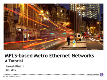
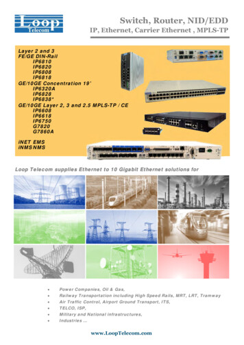
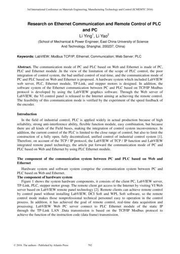
3rd International Conference on Materials Engineering, Manufacturing Technology and Control (ICMEMTC 2016)Research on Ethernet Communication and Remote Control of PLCand PCLi Ying1, Li Yao2(School of Mechanical & Power Engineer, East China University of ScienceAnd Technology, Shanghai, 200237, China)Keywords: LabVIEW; Modbus TCP/IP; Ethernet; Communication; Web Server; PLCAbstract. The communication mode of PC and PLC based on Web and Ethernet is made of PC,PLC and Ethernet module .In the view of the limitation of the scope of PLC control, the poorintegration of control system, the bad unified control of real-time, and the communication mode ofPC and PLC based on Web and Ethernet is proposed. A hardware system which included LabVIEWweb server, PLC, Ethernet module, TP-Link, and stepper motors is designed. In addition, thesoftware system of the Ethernet communication between PC and PLC based on TCP/IP Modbusprotocol is developed by using the LabVIEW graphics software. Through the Web server ofLabVIEW, the VI control panel is released to the Internet aiming at achieving the remote control.The feasibility of this communication mode is verified by the experiment of the speed feedback ofthe encoder.IntroductionIn the field of industrial control, PLC is applied widely in actual production because of highreliability, strong anti-interference ability, flexible function module, easy combination, but becausethere are all kinds of the Field buses, making the integration of control system inconvenience. Inaddition, the current control of the PLC is limited to the close range of control, but also to limit theconstruction of a fully open, fully decentralized, unified control of industrial control system [1].Therefore, on account of the TCP / IP protocol, the LabVIEW of TCP / IP function and LabVIEWintegrated remote panel technology, the article put forward the communication mode of PC andPLC based on Web and Ethernet by using PLC Ethernet module.The component of the communication system between PC and PLC based on Web andEthernetHardware system and software system comprise the communication system between PC andPLC based on Web and Ethernet.The component of hardware systemFigure 1 shows the system hardware components, it consists of the client PC, LabVIEW server,TP-Link, PLC, stepper motor group. The remote client get access to the Internet by visiting VI Webserver based on LabVIEW remote panel technology [2]. Remote clients can achieve remote controlby control panel without installing LabVIEW, DCI Soft and WPL Soft software, so the remotecontrol mode makes those nonprofessional technical personnel easy to operation in the controlprocess. In addition, it has achieved the goal of remote control, real-time data acquisition andprocessing. LabVIEW Web PC server connect to PLC Ethernet module of the static IPthrough the TP-Link LAN .Data transmission is based on the TCP/IP Modbus protocol toachieve the function of the instruction code (data frame) transmission. 2016. The authors - Published by Atlantis Press792
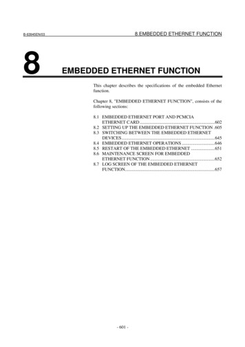
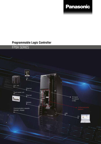
Fig.1 Hardware System CompositionThe component of software systemThe software system of the communication between PC and PLC based on Web and Ethernetconsists of PC and PLC, including the PC cover remote clients have access to visiting to theLabVIEW of Web server and the Ethernet communication between PC and PLC, while PLCincludes the Ethernet communication of between PLC and PC. Communication protocol is ModbusTCP / IP protocol and Ethernet communication realized by PLC module, thecomponent ofsoftware system as shown in Figure 2.Fig.2 Software System CompositionCommunication protocol and Communication processModbus TCP/IP protocolThe communication protocol of the communication mode of PC and PLC based on Web andEthernet is Modbus TCP/IP protocol, TCP/IP Modbus protocol is formed on the Modbus applicationlayer protocol, and its data (ADU) contains the message header, function code, data 3 parts. Asshown in table 1.Table1 Modbus TCP/IP data frameMBAP headerFunction codedataThe length of MBAP Header is seven byte, it is composed of four parts [3] such as thetransaction identifier for the transmission symbol, in master / slave communication the sign ofMODBUS request or response of transmission, usually by the master to generate, from the stationin response to a request for copy the value; protocol identifier for the deal marks, its value is 0 thatindicates the Modbus protocol, while the value is 1which indicates UN-TE protocol; Length793
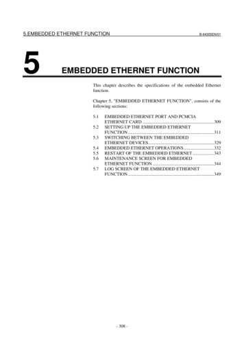
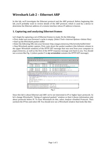
indicates the length of the sum of the domain subsequent bytes; Unit identifier is mark unit, used todefine the device address of the station.Table.2 MBAP HeaderTransactionProtocol IdentifiedLengthUnit Identifier00 0000 0000 0601MBAP header the transaction identifier usually sets to 00 00, indicates the server copy; protocolidentifier usually sets to 00 00, indicates MODBUS protocol; the value of Length is 06 00,representing the data length; unit identifier value is 01 indicates the device address of the station.Communication processAccording to communication mode, remote control system is divided into two types: client andserver mode (C/S mode) and browser / server mode (B/S mode) [4]. B/S simplifies the client, youdo not have to install different programs in different clients, and can also set the permissions ofaccess to improve the security of the system. The system update is mainly completed by the Webserver. LabVIEW in the remote panel (Front Panel Remote) technology is one of B/S mode [5], thecustomers have access to acquiring the power of control mainly through the Web LabVIEW server.Fig.3 Communication FlowchartAs shown in Figure 3, the clients get control permissions from the Web LabVIEW server forcontrolling the VI front panel. When PLC Ethernet ports open, LabVIEW adopts embedded TCP /IP protocol of network communication, this paper makes PLC as the server and PC as the client,using LabVIEW node function TCP Open [6], the port number 502 and the default IP ofDVPEN01-SL to establish the connection between PC and PLC. For example, IP's DVPEN01-SLaddress: [192.168.0.4]; subnet mask: [255.255.255.0]; default gateway: PC; IP [192.168.0.1] for192.168.0.3. Use the write function of TCP nodes to send function instruction code to PLC, forexample, a group of data frames for 0000 0000 0006 0105 0800FF00, 0000 0000 0006 representsfixed data packet headers, 01 indicates the PLC of station number, 05 represents the function codeof drive a single coil, 0800FF00 indicates stepper motor driver data code expression.794
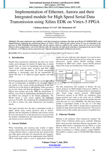
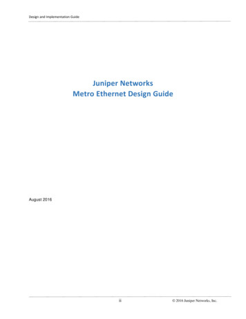
Communication and control experimentIn order to verify the feasibility of the communication between PLC and PC based on Web andEthernet, That the PC read and write operation of PLC is carried out under the condition of Ethernetcommunication in Ethernet module. In the experiment, it is mainly to monitor and adjust the speedof the 57BYGH250C step motor, the upper computer is based on the LabVIEW development of theman-machine interface and monitoring interface. In communications, the LabVIEW of TCP toolkitand DVPEN01 Ethernet module finish communication connection in TP-Link Lan. Informationfeedback, the rotary encoder stepper motor speed real-time feedback to the PLC, and then, the hostcomputer read or write the PLC of internal register, thus completing the data interaction of the hostcomputer and stepper motor.Figure 4 shows that PC and PLC achieve Ethernet communication through the PLC of IP address192.168.0.4 and port number 502. Using TCP/IP Modbus communication protocol, the header partof the code is 00000000000601, the function code is 03, the data is 10000001. This data frameconvey the command of read the internal register D0 to PLC, read TCP function starts reading theencoder registers in the register D0, the sampling period of the program is 1 second. Finally theLabVIEW graphical interface display the stepper motor speed feedback.Fig.4 Stepper Motor Encoder Feedback CodeIn addition, written in WPLSOFT PLC program code [8] as shown in Figure 5, which PLSYk1000 K0 Y0 said sends pulse frequency 1000Hz to PLC continuously, pulse infinite number ofpulses, SPD x1 k1000 d0 represented read send existing registers d0 pulse number every second ,the formula n 60 * [10] 3 x D0/nt (n for the encoder to turn a circle of pulse number is 1000,and t is the pulse time 1000ms) is used for translating into stepper motor speed.Fig.5 PLC Program Executing CodeDue to the LabVIEW embedded web server function, so there is no need to develop a webservice application, only need simple to set up remote clients can upgrade the original stand-aloneversion of the measurement and control system for web remote measurement and control system.Remote clients can access the web publishing LabVIEW VI in VI control conditions to achieveremote control client, according to the need of actual production, the user can set the parametervalues in order to achieve the control objective, the remote control interface as shown in Figure 6.795
Fig.6 Remote Control InterfaceConclusionThe control mode of Web page has changed the traditional one to one, short distance controlmode, this kind of control mode is easy to operate for nonprofessionals, and strong real-timeoperation enable the operator conduct real-time data interaction [9] with the control object.LabVIEW graphics software remote panel technology enables Web server easy to create andaccessible. In addition, in the communication between PC and PLC. Compared with the traditionalRS232 serial communication, Ethernet communication mode not only in the data transmissionspeed and the amount of data occupy obvious advantages, importantly, it expands thecommunication range and the lower position machine control, not just a PC controls a PLC, but aPC can conduct with a plurality of PLC to realize the data read and write between PLC and can beused for data of each transmission, greatly increased the flexibility of real-time control, speed,distance [10].References[1] Shi Su-min, Liu Jian-xin, Jin-Peng, Wu Qin-bin. Development of Ethernet CommunicationSystem between PLC and PC for Automobile Sunroof Testing Control System [J].MachineTool&Hydraulics.2013, 41(16):132-134[2] Li Ji-rong , He Xiang-chu .Two Methods to Publish Web Page by LabVIEW WedSever[J].Instrumentation Technology,2003,(5):13-15[3]Zhou Wen-yi, Fang Jun-ya, Zhu Zi-huan. Control System of Servo Motor Based on LabVIEWand Modbus/TCP[J].Measurement & Control Technology.2015,34(3):83-85[4] Zhao Xin-hua.Remote Virtual Instrument technology Based on LabVIEW[D].Harbin: Schoolof Mechanical and Engineering ,Harbin University of Science and Technology,2005) [5]LiuChuan-hui, Liu Ji-sheng. Research on application of remote-control of machine usingVI[J].Machinery Design &Manufacture.2007,(2):90-91[6] Chen Xi-hui,Zhang Yin-hong. LabVIEW8.20 Programming From entry to the master[M].Beijing: Tsinghua University Publishing House,2007.[7] DVP0204310-02,DVPEN01-SL.Ethernet Communication Module Operation Manual[S].2012[8] Zhang Xi-chuan. Application of delta ES/EX/SS series PLC technology [M].Beijing:ChinaPower Press,2009[9] Xiong Wei-li, Tang Bin-bin, Chen Min-fang. Online Remote water Treatment MonitoringSystem Based onLabVIEW andWeb Technologies [J].Process Automation796
Instrumentation,2012,33(8);41-44.[10] Liang De-chun, Fang Jiang-long, Tao Yi-min . Design of Ethernet Communication of NCSystem[J].Machinery, 2008,46(1):33-35797
Ethernet is Modbus TCP/IP protocol, TCP/IP Modbus protocol is formed on the Modbus application layer protocol, and its data (ADU) contains the message header, function code, data 3 parts. . Control System of Servo Motor Based on LabVIEW and Modbus/TCP[J].Measurement & Control Technology.2015,34(3):83-85 [4] Zhao Xin-hua.Remote Virtual .