Transcription
EtherNet/IP Controller to ModbusMaster Communication viaDeviceMaster EIP-MOD GatewaysFor more information: 1.800.926.6876 763.957.6000 www.comtrol.com1
CONTENTS1. Introduction32. Configure Interfaces to Modbus Master(s)42.1 Serial Modbus Master(s)42.2 Modbus/TCP Master(s)52.3 Modbus RTU/ASCII over Ethernet TCP/IP Master(s)63. Communicate via a Class1 Connection73.1 Shared Memory Configuration83.1.1 Default Configuration83.1.2 Creating a Custom Class 1 Interface103.2 Configuring an I/O Ethernet Module on a ControlLogix PLC113.3 Class 1 Connection Example143.3.1 Modbus Master(s) Configuration153.3.2 Example of a Running System194. Communicate via PLC Tags and Files274.1 Shared Memory Configuration284.2 PLC Tag Definitions294.3 PLC File Definitions294.4 Example of Tag to/from Modbus Communication Between an EtherNet/IP PLC and aModbus Master314.4.1 EtherNet/IP Tag Definitions314.4.2 DeviceMaster EIP-MOD Configuration324.4.3 Modbus Master Configuration344.4.4 Example Running System36For more information: 1.800.926.6876 763.957.6000 www.comtrol.com2
1. INTRODUCTIONThis document is intended to explain how to provide communication between EtherNet/IP controllers and Modbus master controllers. EtherNet/IP Controllers Include: CIP compliant controllers that support Class 1 connections. These include numerousPLCs, HMIs, SCADA systems, OPC Servers, etc. Limited CIP controllers that communicate through PCCC messages over EtherNet/IP.These include MicroLogix, SLC 5/05 and PLC-5 PLCs as well as some HMIs and OPCservers.Modbus master controllers include many types of PLCs, HMIs, SCADA systems, OPC servers,custom applications and many others. The Modbus master interfaces supported by the DeviceMaster EIP-MOD gateway include the following: Serial Modbus RTU/ASCII interfaces. RS-485, RS-232, RS-422, selectable baud rates,parity, etc. Modbus TCP interfaces via standard socket port 502 and up to seven other configurable ports. (503,505,506, etc.) Modbus RTU/ASCII over Ethernet TCP/IP. A highly configurable interface is provided totailor the socket interface(s) for different environments.The steps necessary to provide communication between an EtherNet/IP controller and a Modbus master involve the following:1. Configure the DeviceMaster EIP-MOD gateway. Configure and enable Shared Memory. Configure the Modbus master interface(s) Serial port– configure any serial port to connect to a Modbus RTU/ASCII serialmaster Modbus TCP interface Modbus RTU/ASCII over Ethernet TCP/IP2.Configure the EtherNet/IP controller(s) (PLC, SCADA, HMI, etc). Via Class1 connection Via Tag or File (depending on PLC type)3.Connect the EtherNet/IP PLC(s) to the DeviceMaster EIP-MOD gateway. IP Addresses should be on same subnet4.Connect the Modbus master(s) to the DeviceMaster EIP-MOD gateway. Serial connection Modbus TCP Modbus RTU/ASCII over Ethernet TCP/IPFor more information: 1.800.926.6876 763.957.6000 www.comtrol.com3
2. CONFIGURE INTERFACES TO MODBUS MASTER(S)2.1 Serial Modbus Master(s)Each serial port on the DeviceMaster EIP-MOD gateway can connect to a serial Modbus Master.To configure a serial port to connect to a serial Modbus Master, go to the embedded serial configuration web page.The following serial master interfaces are supported: Modes – RS/232, RS-485, RS-422, etc. Modbus/RTU-to-Master – connects directly to a Modbus/RTU serial master Modbus/ASCII-to-Master – connects directly to a Modbus/ASCII serial master Modbus/RTU-to-Master/Slaves – connects to a RS-485 or RS-422 serial bus containing aModbus/RTU serial master and one or more Modbus/RTU serial slave devices Modbus/ASCII-to-Master/Slaves – connects to a RS-485 or RS-422 serial bus containing aModbus/ASCII serial master and one or more Modbus/ASCII serial slave devicesFor more information: 1.800.926.6876 763.957.6000 www.comtrol.com4
2.2 Modbus/TCP Master(s)The standard Modbus/TCP socket port is, be default, always enabled. To configure other socketports to receive Modbus/TCP messages, go to the Modbus/TCP configuration web page. Up toseven additional TCP/IP socket ports can be configured:Note: The default TCP/IP ports are recommended as they do not interfere with other definedinterfaces on the DeviceMaster EIP-MOD gateways. For a complete list of defined TCP/IP ports,please go tohttps://en.wikipedia.org/wiki/List of TCP and UDP port numbers.For more information: 1.800.926.6876 763.957.6000 www.comtrol.com5
2.3 Modbus RTU/ASCII over Ethernet TCP/IP Master(s)To connect a Modbus Master that communicates using Modbus RTU/ASCII messages over Ethernet TCP/IP connections, go to the Modbus over TCP configuration page:Up to total of six connections can be supported per Modbus over TCP configuration. Enable must be selected. One Connect To connection can be made by setting the Connect To Mode to Connect-Always and configuring the Connect Port and Connect IP Address to that of the listeningapplication. Up to six Listen type connections can made by selecting Listen and configuring the ListenPort. The default Listen Port is acceptable in most instances.For more information: 1.800.926.6876 763.957.6000 www.comtrol.com6
3. COMMUNICATE VIA A CLASS1 CONNECTIONThis method involves setting up a Class1 connection to the DeviceMaster EIP-MOD gateway onthe EtherNet/IP PLC.The EtherNet/IP Class1 interface allows an EtherNet/IP Controller to directly communicate to theShared Memory on the DeviceMaster EIP-MOD gateway. The Class 1 interface definition directlycorrelates to the Shared Memory configuration. In order to change Class 1 interface definition,the Shared Memory must be re-configured.For more information: 1.800.926.6876 763.957.6000 www.comtrol.com7
3.1 Shared Memory ConfigurationThe DeviceMaster EIP-MOD gateway provides a configurable Class 1 interface to and from theShared Memory blocks. While some EtherNetIP controllers restrict the data size of Class1 connections to no more than 512 bytes, other controllers provide for larger Class1 connections. Youwill need to obtain the capabilities of your EtherNet/IP controller in order to create the maximum sized Class1 interface for your system.3.1.1 Default ConfigurationThe default Shared Memory configuration provides the following Class1 interface: Read access from Holding Register block 1 and Coils block 1. Write access to Holding Register block 2 and Coils block 2.For more information: 1.800.926.6876 763.957.6000 www.comtrol.com8
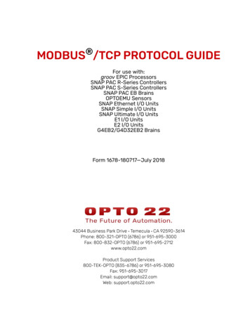
The EtherNet/IP Class 1 interface web page displays the Class 1 parameters:Where the following Class1 interfaces are supported:Input (To PLC)Holding Register Block 1 OnlyCoil Block 1 OnlyBoth Holding Register Block 1 and Coil Block 1Output (From PLC)Holding Register Block 2 OnlyCoil Block 2 OnlyBoth Holding Register Block 2 and Coil Block 2InstanceLength (in bytes)1011091011 - 4001 - 401 - 44011812611840040440Default Shared Memory ConfigurationFor more information: 1.800.926.6876 763.957.6000 www.comtrol.com9
3.1.2 Creating a Custom Class 1 InterfaceIf the default Class 1 interface is not suitable for your system, then you can create a customClass 1 interface by changing the Shared Memory configuration.To change the Class 1 interface on the DeviceMaster EIP-MOD gateway, you will need to makethe following changes to the Shared Memory Configuration. Modifying the Read (Input) Access: To add additional Shared memory blocks, select the Class1 Read Enable option forthe desired block. To remove existing Shared memory blocks, deselect the Class1 Read Enable optionfor the desired block. Modifying the Write (Output) Access: To add additional Shared memory blocks, set the Write Master(s) option to EIP Class1for the desired block. To remove a Shared memory block from write access, change to Write Master(s) option to a setting other than EIP Class1 such as All (Except Class). Click on Apply Settings to save the configuration settings. The custom Class 1 interface will now be displayed on the Data Mapping/EtherNetIP Class1embedded web page.For more information: 1.800.926.6876 763.957.6000 www.comtrol.com10
3.2 Configuring an I/O Ethernet Module on a ControlLogix PLCIn RsLogix, each DeviceMaster EIP-MOD gateway must be set up as a Generic Ethernet Moduleto interface to the PLC via a Class 1 connection. The class 1 interface, as shown above, is displayed on the EtherNetIP Class1 web page:1. First, right click on the Ethernet module on RSLogix5000 and select New Module .2. Click on Communications.3. Scroll down and select Generic Ethernet Module.4. Click on OK. The following pane will appear.a. Enter a Name.b. Select the Comm Format as Data-INT.For more information: 1.800.926.6876 763.957.6000 www.comtrol.com11
c. Enter the IP Address of the gateway.d. Using the data displayed on the Class 1 Overview web page, enter the Connection Parameters.5. Click on OK. The following pane will appear:a. The faster allowable RPI is 10 ms.b. Both Unicast, (point-to-point), and Multicast, (one-to-many), connections are supported.6. Click on OK. The module will be added.7. View the corresponding Input and Output data tags created when the gateway module wasadded. Once the PLC has connected to the DeviceMaster EIP-MOD gateway, these tags willcommunicate directly to the configured Shared Memory blocks.Input tag:For more information: 1.800.926.6876 763.957.6000 www.comtrol.com12
Output tag:For more information: 1.800.926.6876 763.957.6000 www.comtrol.com13
3.3 Class 1 Connection ExampleThe following details an example of using a Class 1 connection to communicate between an EtherNet/IP controller and a Modbus master.The following setup will be used: The Class1 connection defined above will be used to connect the ControlLogix PLC to the DeviceMaster EIP-MOD gateway. The default Shared Memory configuration displayed above will also be used. This will provide: Input (to PLC) Class1 connection between Shared Memory Holding Register block 1and Shared Memory Coils block 1. Output (from PLC) Class1 connection between Shared Memory Holding Register block2 and Shared Memory Coils block 2. A Modbus TCP master writing to the Shared Memory Holding Register block 1 and readingfrom Shared Memory Holding Register block 2. A Modbus TCP master writing to the Shared Memory Coil block 1 and reading from SharedMemory Coil block 2.Relevant diagnostics pages will be shown for the running connection.For more information: 1.800.926.6876 763.957.6000 www.comtrol.com14
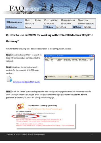
3.3.1 Modbus Master(s) ConfigurationThe Modbus Poll application was used to demonstrate Modbus TCP master functionality. Available Modbus masters include: Modbus TCP master(s) via socket port 502 as well as up to seven configurable socket ports. Modbus/RTU and/or Modbus/ASCII serial master(s) vis a serial port. Modbus/RTU and/or Modbus/ASCII over Ethernet TCP/IP masters via the TCP/IP Configuration(s).3.3.1.1 Modbus TCP Master to Holding Registers ConfigurationRead 100 words of data received from EtherNet/IP PLC via Shared Memory Holding Registersblock 2:Where: Slave ID 252 (Device ID of Shared Memory) Address 201 (Start address of Holding Registers block 2) Quantity 100 registers (valid range: 1-125)For more information: 1.800.926.6876 763.957.6000 www.comtrol.com15
Write 100 words of data to be sent to the EtherNet/IP PLC via Shared Memory Holding Registersblock 1:Where: Slave ID 252 (Device ID of Shared Memory) Address 1 (Start address of Holding Registers block 1) Quantity 100 registers (valid range: 1-123)For more information: 1.800.926.6876 763.957.6000 www.comtrol.com16
3.3.1.2 Modbus TCP Master to Coils ConfigurationRead 100 coils of data received from EtherNet/IP PLC via Shared Memory Coil block 2:Where: Slave ID 252 (Device ID of Shared Memory) Address 321 (Start address of Coil block 2) Quantity 100 coil (valid range: 1-2240) Note: 320 is the size of each coil block. To read only the coils in Shared Memory Coilblock 2, the length should be set to no larger than 320.For more information: 1.800.926.6876 763.957.6000 www.comtrol.com17
Write 100 coils of data to be sent to the EtherNet/IP PLC via Shared Memory Coil block 1:Where: Slave ID 252 (Device ID of Shared Memory) Address 1 (Start address of Coil block 1) Quantity 100 coils (valid range: 1-320) Note: 320 is the size of each coil block – not the maximum size of a Write Coils Modbusmessage. The next Shared Memory Coil block, block 2, is connected to the Class connection and is not writeable by a Modbus master.For more information: 1.800.926.6876 763.957.6000 www.comtrol.com18
3.3.2 Example of a Running System3.3.2.1 PLC Class1 Memory3.3.2.1.1 Input DataThe next two diagrams display the input data received from the Shared Memory on the GW EIP/ASCII.The first 200 INTs are received directly from Holding Registers block 1:The last 20 INTs contain coil data received directly from Coil block 1:For more information: 1.800.926.6876 763.957.6000 www.comtrol.com19
3.3.2.1.2 Output DataThe next two diagrams display the output data sent to the Shared Memory on the GW EIP/ASCII.The first 200 INTs are sent directly to Holding Registers block 2.The last 20 INTs contain coil data are sent directly to Coil block 2:For more information: 1.800.926.6876 763.957.6000 www.comtrol.com20
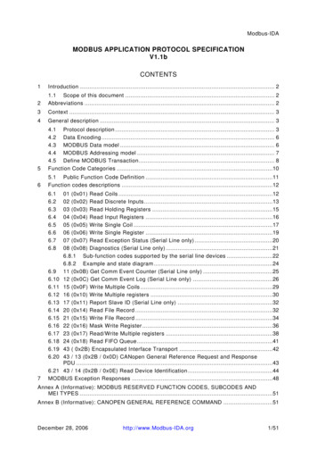
3.3.2.2 Modbus TCP/Controller(s) DataThis diagram displays the Modbus TCP master: Reading Shared Memory Holding Registers block 2 starting at address 201. Writing Shared Memory Holding Registers block 1 starting at address 1.For more information: 1.800.926.6876 763.957.6000 www.comtrol.com21
This diagram displays the Modbus TCP master: Reading Shared Memory Coil block 2 starting at address 321. Writing Shared Memory Coil block 1 starting at address 1.For more information: 1.800.926.6876 763.957.6000 www.comtrol.com22
3.3.2.3 DeviceMaster EIP-MOD Gateway Embedded Diagnostic Pages3.3.2.3.1 EtherNet/IP Interface StatisticsThis page displays the EtherNet/IP statistics for the running system.For more information: 1.800.926.6876 763.957.6000 www.comtrol.com23
3.3.2.3.2 Modbus TCP StatisticsThis page displays the Modbus TCP interface statistics:For more information: 1.800.926.6876 763.957.6000 www.comtrol.com24
3.3.2.3.3 Shared Memory ContentsThese pages display the contents and statistics for the applicable Shared Memory blocks.Holding Register Block1 – Data Received from Modbus TCP Master and Sent to EtherNet/IP PLC:Coil Block1 – Data Received from Modbus TCP Master and Sent to EtherNet/IP PLC:For more information: 1.800.926.6876 763.957.6000 www.comtrol.com25
Holding Register Block 2 – Data Received from EtherNet/IP PLC and read by the Modbus TCPmaster:Coil Block 2 – Data Received from EtherNet/IP PLC and read by the Modbus TCP master:For more information: 1.800.926.6876 763.957.6000 www.comtrol.com26
4. COMMUNICATE VIA PLC TAGS AND FILESThis method involves configuring the Data Mapping feature on the DeviceMaster EIP-MOD gateway to provide an interface between the EtherNetIP controllers memory and the Shared Memory. This method is only possible if your EtherNet/IP controller supports CIP table read and writeor PCCC messages.For more information: 1.800.926.6876 763.957.6000 www.comtrol.com27
4.1 Shared Memory ConfigurationThe Shared Memory interface in the DeviceMaster EIP-MOD gateway operates in the same manner towards the Data Mapping system as it does towards other Modbus controllers. It treats theData Mapping subsystem as another type of Modbus controller.The Data Mapping subsystem can access the Shared Memory blocks if the following guidelinesare followed: The Shared Memory must be enabled. The Shared Memory device Id must not conflict with any Modbus slaves attached to the gateway either directly or remotely. If this occurs, the Modbus slave device will not be accessibl All Data Mapping configurations that access the Shared Memory must: Use the configured Shared Memory device Id. Use valid address/length ranges for the Shared Memory. Any out of address rangeconfigurations will be rejected. For Data Mapping write accesses, the Shared Memory block Write Master(s) settingmust be set to: For Tag/File to Modbus Data Mapping configurations either: All (Except Class1) EIP TAG/FILE and the IP address of the EtherNet/IP controller. For Modbus to Modbus Data Mapping configurations either: All (Except Class1) Modbus to Modbus The appropriate function codes must be used. Valid read function codes for Holding Register blocks are: Read Holding Registers (03) Read Input Registers (04) Valid read function codes for Coil blocks are: Read Coil Status (01) Read Input Status (02) Valid write function codes for Holding Register blocks are: Write Single Register (06) Write Multiple Holding Registers (16) Valid write function codes for Coil blocks are: Write Single Coil (01) Write Multiple Coils (15)For more information: 1.800.926.6876 763.957.6000 www.comtrol.com28
4.2 PLC Tag DefinitionsPLC tags are memory variables defined in RSLogix5000 and similar PLC programs. The tags musthave the following characteristics: Tags must be public so that other EtherNet/IP controllers can read and/or write to them. InRSLogix5000, these tags are Controller type tags with the External Access attribute set toRead/Write or Read Only. Tags must be either single entry or one-dimensional arrays. The Tag Name should NOT include brackets, whether the tag is single entry or an array. The tag data type must correlate to the Data Type selected for the tag. The tag must be long enough to contain all required data.Data Type RSLogix5000 Data Type(s) Example(s)Required Modbus MemorySINTCan be either: Single SINT Array of SINTsNamevarSintvarSintArrayData TypeSINTSINT[40]One Holding or InputRegister for every two SINTsINTCan be either: Single INT Array of INTsNamevarlintvarlintArrayData TypeINTINT[20]One Holding or InputRegister for each INTDINTCan be either: Single DINT Array of DINTsNamevarDintvarDintArrayData TypeDINTDINT[10]Two Holding or InputRegisters for each DINTBOOLCan only be: Single BOOLNamevarBOOLData TypeBOOLOne Coil or Input Status for each BOOL.One Holding or Input Register per BOOL.BIT ARRAYCan only be: Array of BOOLsNameData TypevarBOOLArrayBOOL[320]One Coil or Input Status for eachBOOL array entry.A Holding or Input Register cancontain up to 16 BOOLs.FLOATCan be either: Single FLOAT Array of FLOATsNamevarFloatvarFloat ArrayTwo Holding or InputRegisters for each FLOAT entry.Data TypeFLOATFLOAT[10]4.3 PLC File DefinitionsPLC files are memory tables defined in RSLogix500, RS Logix5 and similar PLC programs. Theyare used in EtherNet/IP controllers such as MicroLogix, SLC 5/05 and PLC-5 PLCs. The files musthave the following characteristics:For more information: 1.800.926.6876 763.957.6000 www.comtrol.com29
Files must be public so that other EtherNet/IP controllers can read and/or write to them. InRSLogix500, the Scope of the file must be set to Global.The File Name must be of the proper format to specify the entry or bit.The file data type must correlate to the Data Type selected for the file.The file must be long enough to contain all required data.Data Type RSLogix5000 Data Type(s) Example(s)Required Modbus MemorySINTN/AINTA file of type N (INTEGER)DINTN/ABOOLA file of type B (BINARY) Only requires a singlebinary bit.NameB32:0B32:0/12BIT ARRAYA file of type B (BINARY)NameB32:0Data TypeB (BINARY)starting at bit 0B32:0/12 B (BINARY)Starting at bit 12One Coil or Input Status for eachBINARY bit entry.A Holding or Input Register cancontain up to 16 bits.FLOATA file of type F (FLOAT)NameF30:0F30:28Two Holding or InputRegisters for each FLOAT entry.N/AN/AData TypeOne Holding or InputN (INTEGER) Register for each INTN (INTEGER)NameN10:0N11:100N/AN/AData TypeB (BINARY) bit 0B (BINARY) bit 12Data TypeF (FLOAT)F (FLOAT)For more information: 1.800.926.6876 763.957.6000 www.comtrol.comOne Coil or Input Status for each BOOL.One Holding or Input Register perBOOL.30
4.4 Example of Tag to/from Modbus Communication Betweenan EtherNet/IP PLC and a Modbus MasterThe following is an example configuration that will move 100 holding registers between a Modbus TCP master and a ControlLogix PLC via Tags.4.4.1 EtherNet/IP Tag DefinitionsThe tags must be defined in the ControlLogix PLC.The configuration of the input tag (FromModbusMaster):The configuration of the output tag (ToModbusMaster):For more information: 1.800.926.6876 763.957.6000 www.comtrol.com31
4.4.2 DeviceMaster EIP-MOD ConfigurationThe Shared Memory must be enabled. For this example, we will use the Shared Memory in itsdefault configuration.Two Data Mapping configurations are required in the DeviceMaster EIP-MOD to move the databetween the EtherNet/IP PLC Tags and the Shared Memory. For this example, we will be usingShared Memory holding Register Holding Register block 7, (EtherNet/IP to Modbus), and block 8(Modbus to EtherNet/IP).For more information: 1.800.926.6876 763.957.6000 www.comtrol.com32
4.4.2.1 Modbus to EtherNet/IP Tag ConfigurationThis configuration: Reads 100 holding registers from the start of Shared Memory Holding Register Block 8. Writes the data to the “FromModbusMaster” tag in the ControlLogix PLC. Repeats cycle every 2000 ms (2 seconds).4.4.2.2 EtherNet/IP Tag to Modbus ConfigurationThis configuration: Reads 100 integers from the “ToModbusMaster” tag in the ControlLogix PLC. Writes the data beginning at the start of Shared Memory Holding Register Block 7. Repeats cycle every 2000 ms (2 seconds).For more information: 1.800.926.6876 763.957.6000 www.comtrol.com33
4.4.3 Modbus Master ConfigurationThe Modbus Poll application was used to demonstrate Modbus TCP master functionality. Available Modbus masters include: Modbus TCP master(s) via socket port 502 as well as up to seven configurable socket ports. Modbus/RTU and/or Modbus/ASCII serial master(s) vis a serial port. Modbus/RTU and/or Modbus/ASCII over Ethernet TCP/IP masters via the TCP/IP Configuration(s).4.4.3.1 Modbus TCP Master to Holding Registers ConfigurationRead 100 words of data received from the EtherNet/IP PLC tag “ToModbusMaster” via SharedMemory Holding Registers block 7:Where: Slave ID 252 (Device ID of Shared Memory) Address 1201 (Start address of Holding Registers block 7) Quantity 100 registers (valid range: 1-125)For more information: 1.800.926.6876 763.957.6000 www.comtrol.com34
Write 100 words of data to be sent to the EtherNet/IP PLC tag “FromModbusMaster” via SharedMemory Holding Registers block 8:Where: Slave ID 252 (Device ID of Shared Memory) Address 1401 (Start address of Holding Registers block 8) Quantity 100 registers (valid range: 1-123)For more information: 1.800.926.6876 763.957.6000 www.comtrol.com35
4.4.4 Example Running System4.4.4.1 Input TagBased on the Read Modbus Write Tag/File configuration, the DeviceMaster EIP-MOD gatewaywrites the data from Holding Registers block 8 to the “FromModbusMaster” tag:For more information: 1.800.926.6876 763.957.6000 www.comtrol.com36
4.4.4.2 Output TagBased on the Read Tag/File Write Modbus configuration, the DeviceMaster EIP-MOD gatewayreads the data from the “ToModbusMaster” tag and then writes it into Holding Registers block 7:For more information: 1.800.926.6876 763.957.6000 www.comtrol.com37
4.4.4.3 Modbus TCP/Controller DataThis diagram displays the Modbus TCP master: Reading Shared Memory Holding Registers block 7 starting at address 1201. Writing Shared Memory Holding Registers block 8 starting at address 1401.For more information: 1.800.926.6876 763.957.6000 www.comtrol.com38
4.4.4.4 DeviceMaster EIP-MOD Gateway Embedded Diagnostic Pages4.4.4.4.1 EtherNet/IP Interface StatisticsThis page displays the EtherNet/IP statistics for the running system.For more information: 1.800.926.6876 763.957.6000 www.comtrol.com39
4.4.4.4.2 Modbus TCP StatisticsThis page displays the Modbus TCP interface statistics:For more information: 1.800.926.6876 763.957.6000 www.comtrol.com40
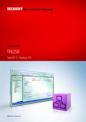
4.4.4.4.3 Shared Memory ContentsThese pages display the contents and statistics for the applicable Shared Memory blocks.Holding Register Block 7 – Data Received from EtherNet/IP PLC and read by the Modbus TCPmaster:For more information: 1.800.926.6876 763.957.6000 www.comtrol.com41
Holding Register Block8 – Data Received from Modbus TCP Master and Sent to EtherNet/IP PLC:For more information: 1.800.926.6876 763.957.6000 www.comtrol.com42
2.2 Modbus/TCP Master(s) The standard Modbus/TCP socket port is, be default, always enabled. To conigure other socket ports to receive Modbus/TCP messages, go to the Modbus/TCP coniguration web page. Up to seven additional TCP/IP socket ports can be conigured: Note: The default TCP/IP ports are recommended as they do not interfere with other deined