Transcription
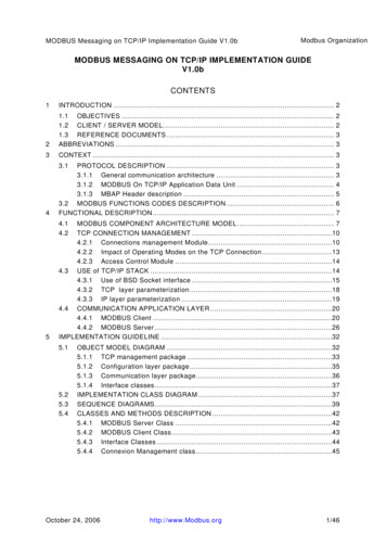
MODBUS Messaging on TCP/IP Implementation Guide V1.0bModbus OrganizationMODBUS MESSAGING ON TCP/IP IMPLEMENTATION GUIDEV1.0bCONTENTS1INTRODUCTION . 221.1 OBJECTIVES .1.2 CLIENT / SERVER MODEL.1.3 REFERENCE DOCUMENTS .ABBREVIATIONS .3CONTEXT . 33.14PROTOCOL DESCRIPTION .3.1.1 General communication architecture .3.1.2 MODBUS On TCP/IP Application Data Unit .3.1.3 MBAP Header description .3.2 MODBUS FUNCTIONS CODES DESCRIPTION .FUNCTIONAL DESCRIPTION.22333345674.14.25MODBUS COMPONENT ARCHITECTURE MODEL . 7TCP CONNECTION MANAGEMENT .104.2.1 Connections management Module .104.2.2 Impact of Operating Modes on the TCP Connection .134.2.3 Access Control Module .144.3 USE of TCP/IP STACK .144.3.1 Use of BSD Socket interface .154.3.2 TCP layer parameterization .184.3.3 IP layer parameterization .194.4 COMMUNICATION APPLICATION LAYER .204.4.1 MODBUS Client .204.4.2 MODBUS Server .26IMPLEMENTATION GUIDELINE .325.15.25.35.4OBJECT MODEL DIAGRAM .325.1.1 TCP management package .335.1.2 Configuration layer package .355.1.3 Communication layer package.365.1.4 Interface classes.37IMPLEMENTATION CLASS DIAGRAM .37SEQUENCE DIAGRAMS.39CLASSES AND METHODS DESCRIPTION .425.4.1 MODBUS Server Class .425.4.2 MODBUS Client Class.435.4.3 Interface Classes .445.4.4 Connexion Management class .45October 24, 2006http://www.Modbus.org1/46
Modbus OrganizationMODBUS Messaging on TCP/IP Implementation Guide V1.0b11.1INTRODUCTIONOBJECTIVESThe objective of this document is to present the MODBUS messaging service overTCP/IP , in order to provide reference information that helps software developers toimplement this service. The encoding of the MODBUS function codes is not describedin this document, for this information please read the MODBUS Application ProtocolSpecification [1].This document gives accurate and comprehensive description of a MODBUS messagingservice implementation. Its purpose is to facilitate the interoperability between thedevices using the MODBUS messaging service.This document comprises mainly three parts: An overview of the MODBUS over TCP/IP protocol A functional description of a MODBUS client, server and gatewayimplementation. An implementation guideline that proposes the object model of an MODBUSimplementation example.1.2CLIENT / SERVER MODELThe MODBUS messaging service provides a Client/Server communication betweendevices connected on an Ethernet TCP/IP network.This client / server model is based on four type of messages: MODBUSMODBUSMODBUSMODBUSMODBUS estIndicationConfirmationResponseMODBUS ServerA MODBUS Request is the message sent on the network by the Client to initiate atransaction,A MODBUS Indication is the Request message received on the Server side,A MODBUS Response is the Response message sent by the Server,A MODBUS Confirmation is the Response Message received on the Client sideThe MODBUS messaging services (Client / Server Model) are used for real timeinformation exchange: between two device applications, between device application and other device, between HMI/SCADA applications and devices, between a PC and a device program providing on line services.October 24, 2006http://www.Modbus.org2/46
MODBUS Messaging on TCP/IP Implementation Guide V1.0bModbus Organization1.3REFERENCE DOCUMENTSThis section gives a list of documents that are interesting to read before this PBSDMSL3MODBUS Application Protocol Specification V1.1a.RFC 1122 Requirements for Internet Hosts -- Communication LayersApplication Data UnitInternet Engineering Task ForceInternet ProtocolMedium Access ControlMODBUSMODBUS Application ProtocolProtocol Data UnitProgrammable Logic ControllerTransport Control ProtocolBerkeley Software DistributionMaximum Segment LifetimeCONTEXT3.13.1.1PROTOCOL DESCRIPTIONGeneral communication architectureA communicating system over MODBUS TCP/IP may include different types of device: A MODBUS TCP/IP Client and Server devices connected to a TCP/IP network The Interconnection devices like bridge, router or gateway for interconnectionbetween the TCP/IP network and a serial line sub-network which permitconnections of MODBUS Serial line Client and Server end devices.October 24, 2006http://www.Modbus.org3/46
Modbus OrganizationMODBUS Messaging on TCP/IP Implementation Guide V1.0bMODBUSClientSerial LineMODBUS ClientTCP/IPMODBUS ClientTCP/IPClientTCP/IPMODBUSMODBUS ServerTCP/IPMODBUS ServerTCP/IPMODBUSServerSerial LineMODBUSServerSerial LineServer TCP/IPgatewayMODBUSSerialFigure 1: MODBUS TCP/IP communication architectureThe MODBUS protocol defines a simple Protocol Data Unit (PDU) independent of theunderlying communication layers. The mapping of MODBUS protocol on specific busesor networks can introduce some additional fields on the Application Data Unit (ADU).ADUAdditional addressFunction codeDataError checkPDUFigure 2: General MODBUS frameThe client that initiates a MODBUS transaction builds the MODBUS Application DataUnit. The function code indicates to the server which kind of action to perform.3.1.2MODBUS On TCP/IP Application Data UnitThis section describes the encapsulation of a MODBUS request or response when it iscarried on a MODBUS TCP/IP network.MODBUS TCP/IP ADUMBAP HeaderFunction codeDataPDUFigure 3: MODBUS request/response over TCP/IPA dedicated header is used on TCP/IP to identify the MODBUS Application Data Unit. Itis called the MBAP header (MODBUS Application Protocol header).October 24, 2006http://www.Modbus.org4/46
MODBUS Messaging on TCP/IP Implementation Guide V1.0bModbus OrganizationThis header provides some differences compared to the MODBUS RTU application dataunit used on serial line: The MODBUS ‘slave address’ field usually used on MODBUS Serial Line isreplaced by a single byte ‘Unit Identifier’ within the MBAP Header. The‘Unit Identifier’ is used to communicate via devices such as bridges,routers and gateways that use a single IP address to support multipleindependent MODBUS end units. All MODBUS requests and responses are designed in such a way that therecipient can verify that a message is finished. For function codes wherethe MODBUS PDU has a fixed length, the function code alone is sufficient.For function codes carrying a variable amount of data in the request orresponse, the data field includes a byte count. When MODBUS is carried over TCP, additional length information iscarried in the MBAP header to allow the recipient to recognize messageboundaries even if the message has been split into multiple packets fortransmission. The existence of explicit and implicit length rules, and use ofa CRC-32 error check code (on Ethernet) results in an infinitesimal chanceof undetected corruption to a request or response message.3.1.3MBAP Header descriptionThe MBAP Header contains the following fields:FieldsLengthDescription -ClientServerTransactionIdentifier2 BytesIdentification of aMODBUS Request /Response transaction.Initialized by theclientRecopied by theserver from thereceivedrequestProtocol Identifier2 Bytes0 MODBUS protocolInitialized by theclientRecopied by theserver from thereceivedrequestLength2 BytesNumber of followingbytesInitialized by theclient ( request)Initialized bythe server (Response)Unit Identifier1 ByteIdentification of aremote slaveconnected on a serialline or on other buses.Initialized by theclientRecopied by theserver from thereceivedrequestThe header is 7 bytes long: Transaction Identifier - It is used for transaction pairing, the MODBUS server copiesin the response the transaction identifier of the request. Protocol Identifier – It is used for intra-system multiplexing. The MODBUS protocolis identified by the value 0. Length - The length field is a byte count of the following fields, including the UnitIdentifier and data fields.October 24, 2006http://www.Modbus.org5/46
MODBUS Messaging on TCP/IP Implementation Guide V1.0b Modbus OrganizationUnit Identifier – This field is used for intra-system routing purpose. It is typicallyused to communicate to a MODBUS or a MODBUS serial line slave through agateway between an Ethernet TCP-IP network and a MODBUS serial line. This field isset by the MODBUS Client in the request and must be returned with the same value inthe response by the server.All MODBUS/TCP ADU are sent via TCP to registered port 502.Remark : the different fields are encoded in Big-endian.3.2MODBUS FUNCTIONS CODES DESCRIPTIONStandard function codes used on MODBUS application layer protocol are described indetails in the MODBUS Application Protocol Specification [1].October 24, 2006http://www.Modbus.org6/46
Modbus OrganizationMODBUS Messaging on TCP/IP Implementation Guide V1.0b4FUNCTIONAL DESCRIPTIONThe MODBUS Component Architecture presented here is a general model includingboth MODBUS Client and Server Components and usable on any device.Some devices may only provide the server or the client component.In the first part of this section a brief overview of the MODBUS messaging servicecomponent architecture is given, followed by a description of each componentpresented in the architectural model.4.1MODBUS COMPONENT ARCHITECTURE MODELRessource Management&Flow rModbus ClientInterfaceModbus ClientModbus BackendInterfaceModbus anagementAccess CtlTCP/IP StackFigure 4: MODBUS Messaging Service Conceptual Architecture Communication Application LayerA MODBUS device may provide a client and/or a server MODBUS interface.A MODBUS backend interface can be provided allowing indirectly the access to userapplication objects.Four areas can compose this interface: input discrete, output discrete (coils), inputregisters and output registers. A pre-mapping between this interface and the userapplication data has to be done (local issue).October 24, 2006http://www.Modbus.org7/46
Modbus OrganizationMODBUS Messaging on TCP/IP Implementation Guide V1.0bPrimary tablesObject typeType ofDiscretes InputSingle bitRead-OnlyCoilsSingle bitRead-WriteInput Registers16-bit wordRead-OnlyHolding Registers16-bit wordRead-WriteDevice application memoryCommentsThis type of data can be provided by an I/O system.This type of data can be alterable by an applicationprogram.This type of data can be provided by an I/O systemThis type of data can be alterable by an applicationprogram.Device application memoryMODBUS accessMODBUS accessInput DiscreteInput DiscreteRCoilsWMODBUS RequestRInput RegistersWOutput Registers¾MODBUS RequestInput RegistersOutput RegistersMODBUS SERVER DEVICEMODBUS SERVER DEVICEFigure 5CoilsMODBUS Data Model withseparate blocksFigure 6MODBUS Data Model with only1 blockMODBUS ClientThe MODBUS Client allows the user application to explicitly control informationexchange with a remote device. The MODBUS Client builds a MODBUS request fromparameter contained in a demand sent by the user application to the MODBUS ClientInterface.The MODBUS Client uses a MODBUS transaction whose management includes waitingfor and processing of a MODBUS confirmation.¾MODBUS Client InterfaceThe MODBUS Client Interface provides an interface enabling the user application tobuild the requests for various MODBUS services including access to MODBUSapplication objects. The MODBUS Client interface (API) is not part ofthisSpecification, although an example is described in the implementation model.¾MODBUS ServerOn reception of a MODBUS request this module activates a local action to read, towrite or to achieve some other actions. The processing of these actions is done totallytransparently for the application programmer. The main MODBUS server functions areto wait for a MODBUS request on 502 TCP port, to treat this request and then to build aMODBUS response depending on device context.¾MODBUS Backend InterfaceThe MODBUS Backend Interface is an interface from the MODBUS Server to the userapplication in which the application objects are defined.Informative Note:October 24, 2006The Backend Interface is not defined in this Specificationhttp://www.Modbus.org8/46
MODBUS Messaging on TCP/IP Implementation Guide V1.0b Modbus OrganizationTCP Management layerInformative Note: The TCP/IP discussion in this Specification is based in part uponreference [2] RFC 1122 to assist the user in implementing the MODBUS ApplicationProtocol Specification [1] over TCP/IP.One of the main functions of the messaging service is to manage communicationestablishment and ending and to manage the data flow on established TCPconnections.¾Connection ManagementA communication between a client and server MODBUS Module requires the use of aTCP connection management module. It is in charge to manage globally messagingTCP connections.Two possibilities are proposed for the connection management. Either the userapplication itself manages TCP connections or the connection management is totallydone by this module and therefore it is transparent for the user application. The lastsolution implies less flexibility.The listening TCP port 502 is reserved for MODBUS communications. It ismandatory to listen by default on that port. However, some markets or applicationsmight require that another port is dedicated to MODBUS over TCP. For that reason, itis highly recommended that the clients and the servers give the possibility to the userto parameterize the MODBUS over TCP port number. It is important to note thateven if another TCP server port is configured for MODBUS service in certainapplications, TCP server port 502 must still be available in addition to anyapplication specific ports.¾Access Control ModuleIn certain critical contexts, accessibility to internal data of devices must be forbidden forundesirable hosts. That’s why a security mode is needed and security process may beimplemented if required. TCP/IP Stack layerThe TCP/IP stack can be parameterized in order to adapt the data flow control, theaddress management and the connection management to different constraints specificto a product or to a system. Generally the BSD socket interface is used to manage theTCP connections. Resource management and Data flow controlIn order to equilibrate inbound and outbound messaging data flow between theMODBUS client and the server, data flow control mechanism is provided in all layersof MODBUS messaging stack.The resource management and flow control module is first based on TCP internal flowcontrol added with some data flow control in the data link layer and also in the userapplication level.October 24, 2006http://www.Modbus.org9/46
MODBUS Messaging on TCP/IP Implementation Guide V1.0b4.2Modbus OrganizationTCP CONNECTION MANAGEMENT4.2.1Connections management Module4.2.1.1General descriptionA MODBUS communication requires the establishment of a TCP connection between aClient and a Server.The establishment of the connection can be activated either explicitly by the UserApplication module or automatically by the TCP connection management module.In the first case an application-programming interface has to be provided in the userapplication module to manage completely the connection. This solution providesflexibility for the application programmer but it requires a good expertise on TCP/IPmechanism.In the second case the TCP connection management is completely hidden to the userapplication that only sends and receives MODBUS messages. The TCP connectionmanagement module is in charge to establish a new TCP connection when it isrequired.The definition of the number of TCP client and server connections is not on the scope ofthis document (value n in this document). Depending on the device capacities thenumber of TCP connections can be different.Implementation Rules :1) Without explicit user requirement, it is recommended to implement the automatic TCPconnection management2) It is recommended to keep the TCP connection opened with a remote device and notto open and close it for each MODBUS/TCP transaction,Remark: However the MODBUS client must be capable of accepting a close requestfrom the server and closing the connection. The connection can be reopened whenrequired.3) It is recommended for a MODBUS Client to open a minimum of TCP connections witha remote MODBUS server (with the same IP address). One connection per applicationcould be a good choice.4) Several MODBUS transactions can be activated simultaneously on the same TCPConnection.Remark: If this is done then the MODBUS transaction identifier must be used touniquely identify the matching requests and responses.5) In case of a bi-directional communication between two remote MODBUS entities (each of them is client and server), it is necessary to open separate connections forthe client data flow and for the server data flow.6) A TCP frame must transport only one MODBUS ADU. It is advised against sendingmultiple MODBUS requests or responses on the same TCP PDUOctober 24, 2006http://www.Modbus.org10/46
Modbus OrganizationMODBUS Messaging on TCP/IP Implementation Guide V1.0bIdleWaitClientServer[Request to a remote[ Event on a socket[connection established][else][ n connections][data][connection request][access ctl][n connections][no access ctl][IP forbidden][IP authorized]Oldest unusedconnection closedConnection refusedConnection accepted[n connections][ n connections]Connection establishment[Connection OK]Active Connection[Connection NOK]Oldest unusedno prioritaryconnection closedConnection establishednetwork transmissionRequest treatmentFigure 7: TCP connection management activity diagram1.Explicit TCP connection managementThe user application module is in charge of managing all the TCP connections: activeand passive establishment, connection ending, etc. This management is done for allMODBUS communication between a client and a server. The BSD Socket interface isused in the user application module to manage the TCP connection. This solution offersa total flexibility but it implies that the application programmer has sufficient TCPknowledge.A limit of number of client and server connections has to be configured taking intoaccount the device capabilities and requirement.2. Automatic TCP connection managementThe TCP connection management is totally transparent for the user application module.The connection management module may accept a sufficient number of client andserver connections.Nevertheless a mechanism must be implemented in case of exceeding the number ofauthorized connection. In such a case we recommend to close the oldest unusedconnection.A connection with a remote partner is established at the first packet received from aremote client or from the local user application. This connection will be closed if atermination arrived from the network or decided locally on the device. On reception of aconnection request, the access control option can be used to forbid device accessibilityto unauthorized clients.October 24, 2006http://www.Modbus.org11/46
Modbus OrganizationMODBUS Messaging on TCP/IP Implementation Guide V1.0bThe TCP connection management module uses the Stack interface (usually BSD Socketinterface) to communicate with the TCP/IP stack.In order to maintain compatibility between system requirements and server resources,the TCP management will maintain 2 pools of connection. The first pool ( priority connection pool) is made of connections that are neverclosed on a local initiative. A configuration must be provided to set this pool up. Theprinciple to be implemented is to associate a specific IP address with each possibleconnection of this pool. The devices with such IP addresses are said to be“marked”. Any new connection that is requested by a marked device must beaccepted, and will be taken from the priority connection pool. It is also necessary toconfigure the maximum number of Connections allowed for each remote device toavoid that the same device uses all the connections of the priority pool. The second pool (non-priority connection pool) contains connections for nonmarked devices. The rule that takes over here is to close the oldest connectionwhen a new connection request arrives from a non-marked device and when thereis no more connection available in the pool.A configuration might be optionally provided to assign the number of connectionsavailable in each pool. However (It is not mandatory) the designers can set the numberof connections at design time if required.4.2.1.2Connection management description Connection establishment :The MODBUS messaging service must provide a listening socket on Port 502, whichpermits to accept new connection and to exchange data with other devices.When the messaging service needs to exchange data with a remote server, it mustopen a new client connection with a remote Port 502 in order to exchange data with thisdistant. The local port must be higher than 1024 and different for each clientconnection.Device@IP1ClientPortsDevice@n(n 1024)ServerPortConnection (@ IP1 n,@IP2 502)502n(n 1024)502IP2ClientPortsServerPortFigure 8: MODBUS TCP connection establishmentIf the number of client and server connections is greater than the number of authorizedconnections the oldest unused connection is closed. The access control mechanismcan be activated to check if the IP address of the remote client is authorized. If not thenew connection is refused.October 24, 2006http://www.Modbus.org12/46
MODBUS Messaging on TCP/IP Implementation Guide V1.0b Modbus OrganizationMODBUS data transferA MODBUS request has to be sent on the right TCP connection already opened. The IPaddress of the remote is used to find the TCP connection. In case of multiple TCPconnections opened with the same remote, one connection has to be chosen to sendthe MODBUS message, different choice criteria can be used like the oldest one, thefirst one. The connection has to maintain open during all the MODBUS communications.As described in the following sections a client can initiate several MODBUStransactions with a server without waiting the ending of the previous one. Connection closingWhen the MODBUS communications are ended between a Client and a Server, theclient has to initiate a connection closing of the connection used for thesecommunications.4.2.2Impact of Operating Modes on the TCP ConnectionSome Operating Modes (communication break between two operational End Points,Crash and Reboot on one of the End Point, ) may have impacts on the TCPConnections. A connection can be seen closed or aborted on one side without theknowledge of the other side. The connection is said to be "half-open".This section describes the behavior for each main Operating Modes. It is assumed thatthe Keep Alive TCP mechanism is used on both end points (See section 4.3.2)4.2.2.1Communication break between two operational end points:The origin of the communication break can be the disconnection of the Ethernet cableon the Server side. The expected behavior is: If no packet is currently sent on the connection:The communication break will not be seen if it lasts less than the Keep Alive timervalue. If the communication break lasts more than the Keep Alive timer value, anerror is returned to the TCP Management layer that can reset the connection.If Some packets are sent before and after the disconnection:The TCP retransmission algorithms (Jacobson's, Karn's algorithms and exponentialbackoff. See section 4.3.2) are activated. This may lead to a stack TCP layer Resetof the Connection before the Keep Alive timer is over. 4.2.2.2Crash and Reboot of the Server end pointAfter the crash and Reboot of the Server, the connection is "half-open" on Client side.The expected behavior is: If no packet is sent on the half-open connection:The TCP half-open connection is seen opened from the Client side as long as theKeep Alive timer is not over. After that an error is returned to the TCP Managementlayer that can reset the connection.If some packets are sent on the half-open connection:The Server receives data on a connection that doesn't exist anymore. The stackTCP layer sends a Reset to close the half-open connection on the Client side 4.2.2.3Crash and Reboot of the ClientAfter the crash and Reboot of the Client, the connection is "half-open" on Server side.The expected behavior is:October 24, 2006http://www.Modbus.org13/46
MODBUS Messaging on TCP/IP Implementation Guide V1.0bModbus Organization No packet is sent on the half-open connection:The TCP half-open connection is seen opened from the Server side as long as theKeep Alive timer is not over. After that an error is returned to the TCP Managementlayer that can reset the connection. If the Client opens a new connection before the Keep Alive timer is over :Two cases have to be studied: The connection opening has the same characteristics as the half-openconnection on the server side (same source and destination Ports, same sourceand destination IP Addresses), therefore the connection opening will fail at theTCP stack level after the Time-Out on Connection Establishment (75s on most ofBerkeley implementations). To avoid this long Time-Out during which it is notpossible to communicate, it is advised to ensure that different source portnumbers than the previous one are used for a connection opening after a rebooton the client side. 4.2.3The connection opening has not the same characteristics as the half-openconnection on the server side (different source Ports, same destination Port,same source and destination IP Address ), therefore the connection is opened atthe stack TCP level and signaled to the Server TCP Management layer.If the Server TCP Management layer only supports one connection from a remoteClient IP Address, it can close the old half-opened connection and use the newone.If the Server TCP Management layer supports several connections from a remoteClient IP Address, the new connection stays opened and the old one also stayshalf-opened until the expiration of the Keep Alive Timer that will return an error tothe TCP Management layer. After that the TCP Management layer will be able toReset the old connection.Access Control ModuleThe goal of this module is to check every new connection and using a list of authorizedremote IP addresses the module can authorize or forbid a remote Client TCPconnection.In critical context the application programmer needs to choose the Access Controlmode in order to secure its network access. In such a case he needs to Authorize/forbidaccess for each remote @IP. The user needs to provide a list of IP addresses and tospecify for each IP address if it’s authorized or not. By default, on security mode, the IPaddresses not configured by the user are forbidden. Therefore with the access controlmode a connection coming from an unknown IP address is closed.4.3USE of TCP/IP STACKA TCP/IP stack provides an interface to manage connections, to send and receive data,and also to do some parameterizations in order to adapt the stack behavior to thedevice or system constraints.October 24, 2006http://www.Modbus.org14/46
MODBUS Messaging on TCP/IP Implementation Guide V1.0bMsgModbusModbus OrganizationThe goal of this section is to givean overview of the Stack interfaceandalsosomeinformationconcerning the parameterization ofthe stack. This overview focuseson t
MODBUS Messaging on TCP/IP Implementation Guide V1.0b . 1 INTRODUCTION . 1.1 OBJECTIVES . The objective of this document is to present the MODBUS messaging service over TCP/IP , in order to provide reference information that helps software developers to . devices connected on an Ethernet TCP/IP network.
