Transcription
Manual ENTF6250TwinCAT 3 Modbus TCP2022-02-16 Version: 1.6
Table of contentsTable of contents1 Foreword . 51.1Notes on the documentation. 51.2Safety instructions . 61.3Notes on information security . 72 Overview. 83 Installation. 93.1System Requirements . 93.2Installation . 93.3Installation Windows CE . 123.4Installing the TwinCAT/BSD . 143.5Licensing . 144 Configuration . 174.1Overview. 174.2TwinCAT Modbus TCP Configurator . 174.3Default Configuration . 195 Diagnosis. 205.1Modbus ADS Diagnosis Interface. 206 PLC libraries . 216.1Overview. 216.2Function blocks. 216.36.2.1FB MBReadCoils (Modbus function 1) . 216.2.2FB MBReadInputs (Modbus function 2). 236.2.3FB MBReadRegs (Modbus function 3) . 256.2.4FB MBReadInputRegs (Modbus function 4) . 276.2.5FB MBWriteSingleCoil (Modbus function 5) . 296.2.6FB MBWriteSingleReg (Modbus function 6) . 316.2.7FB MBWriteCoils (Modbus function 15). 326.2.8FB MBWriteRegs (Modbus function 16) . 346.2.9FB MBReadWriteRegs (Modbus-Funktion 23) . 366.2.10FB MBDiagnose (Modbus function 8). 386.2.11UDP . 40Global constants . 536.3.1Library Version. 537 Samples . 547.1Sample: Digital IO access . 547.2Sample: Multiple register access . 558 Appendix . 568.1Overview. 568.2ADS Return Codes . 56TF6250Version: 1.63
Table of contents4Version: 1.6TF6250
Foreword1Foreword1.1Notes on the documentationThis description is only intended for the use of trained specialists in control and automation engineering whoare familiar with applicable national standards.It is essential that the documentation and the following notes and explanations are followed when installingand commissioning the components.It is the duty of the technical personnel to use the documentation published at the respective time of eachinstallation and commissioning.The responsible staff must ensure that the application or use of the products described satisfy all therequirements for safety, including all the relevant laws, regulations, guidelines and standards.DisclaimerThe documentation has been prepared with care. The products described are, however, constantly underdevelopment.We reserve the right to revise and change the documentation at any time and without prior announcement.No claims for the modification of products that have already been supplied may be made on the basis of thedata, diagrams and descriptions in this documentation.TrademarksBeckhoff , TwinCAT , TwinCAT/BSD , TC/BSD , EtherCAT , EtherCAT G , EtherCAT G10 , EtherCAT P ,Safety over EtherCAT , TwinSAFE , XFC , XTS and XPlanar are registered trademarks of and licensed byBeckhoff Automation GmbH.Other designations used in this publication may be trademarks whose use by third parties for their ownpurposes could violate the rights of the owners.Patent PendingThe EtherCAT Technology is covered, including but not limited to the following patent applications andpatents:EP1590927, EP1789857, EP1456722, EP2137893, DE102015105702with corresponding applications or registrations in various other countries.EtherCAT is a registered trademark and patented technology, licensed by Beckhoff Automation GmbH,GermanyCopyright Beckhoff Automation GmbH & Co. KG, Germany.The reproduction, distribution and utilization of this document as well as the communication of its contents toothers without express authorization are prohibited.Offenders will be held liable for the payment of damages. All rights reserved in the event of the grant of apatent, utility model or design.TF6250Version: 1.65
Foreword1.2Safety instructionsSafety regulationsPlease note the following safety instructions and explanations!Product-specific safety instructions can be found on following pages or in the areas mounting, wiring,commissioning etc.Exclusion of liabilityAll the components are supplied in particular hardware and software configurations appropriate for theapplication. Modifications to hardware or software configurations other than those described in thedocumentation are not permitted, and nullify the liability of Beckhoff Automation GmbH & Co. KG.Personnel qualificationThis description is only intended for trained specialists in control, automation and drive engineering who arefamiliar with the applicable national standards.Description of symbolsIn this documentation the following symbols are used with an accompanying safety instruction or note. Thesafety instructions must be read carefully and followed without fail!DANGERSerious risk of injury!Failure to follow the safety instructions associated with this symbol directly endangers the life and health ofpersons.WARNINGRisk of injury!Failure to follow the safety instructions associated with this symbol endangers the life and health of persons.CAUTIONPersonal injuries!Failure to follow the safety instructions associated with this symbol can lead to injuries to persons.NOTEDamage to the environment or devicesFailure to follow the instructions associated with this symbol can lead to damage to the environment orequipment.Tip or pointerThis symbol indicates information that contributes to better understanding.6Version: 1.6TF6250
Foreword1.3Notes on information securityThe products of Beckhoff Automation GmbH & Co. KG (Beckhoff), insofar as they can be accessed online,are equipped with security functions that support the secure operation of plants, systems, machines andnetworks. Despite the security functions, the creation, implementation and constant updating of a holisticsecurity concept for the operation are necessary to protect the respective plant, system, machine andnetworks against cyber threats. The products sold by Beckhoff are only part of the overall security concept.The customer is responsible for preventing unauthorized access by third parties to its equipment, systems,machines and networks. The latter should be connected to the corporate network or the Internet only ifappropriate protective measures have been set up.In addition, the recommendations from Beckhoff regarding appropriate protective measures should beobserved. Further information regarding information security and industrial security can be found in ourhttps://www.beckhoff.com/secguide.Beckhoff products and solutions undergo continuous further development. This also applies to securityfunctions. In light of this continuous further development, Beckhoff expressly recommends that the productsare kept up to date at all times and that updates are installed for the products once they have been madeavailable. Using outdated or unsupported product versions can increase the risk of cyber threats.To stay informed about information security for Beckhoff products, subscribe to the RSS feed at https://www.beckhoff.com/secinfo.TF6250Version: 1.67
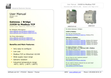
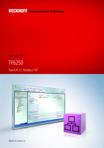
Overview2OverviewThe TwinCAT Modbus TCP server enables to communicate over a network connection (TCP/IP) with theModbus protocol.Modbus is an open standard in industrial communication which will be maintained by the independentModbus Organization.The protocol is based on a client/server-architecture. Therefore the product can be used as client or asserver:Server functionality [} 17]:(1) The TwinCAT Modbus TCP server enables to access the TwinCAT PLC. The Modbus register and I/O'sare then mapped to TwinCAT PLC areas.Client functionality [} 21]:(2) The supplied PLC-library allows to communicate with other Modbus devices to request data (e.g.measured values, states) and control them.8Version: 1.6TF6250
Installation3Installation3.1System RequirementsTechnical DataTarget SystemTF6250 TwinCAT 3 Modbus TCP ServerWindows NT/2000/XP/Vista/7PC (x86-compatible)3.0.0TC1200 TC3 PLCMin. TwinCAT-VersionMin. TwinCAT-LevelRequirementsDevelopment environmentTwinCAT v3.0.03.2Target system typePC or CX (x86, ARM)PLC libraries to be linkedTc2 ModbusSrvInstallationThe following section describes how to install the TwinCAT 3 Function for Windows-based operatingsystems.ü The TwinCAT 3 Function setup file was downloaded from the Beckhoff website.1. Run the setup file as administrator. To do this, select the command Run as administrator in the contextmenu of the file.ð The installation dialog opens.2. Accept the end user licensing agreement and click Next.TF6250Version: 1.69
Installation3. Enter your user data.4. If you want to install the full version of the TwinCAT 3 Function, select Complete as installation type. Ifyou want to install the TwinCAT 3 Function components separately, select Custom.10Version: 1.6TF6250
Installation5. Select Next, then Install to start the installation.ð A dialog box informs you that the TwinCAT system must be stopped to proceed with the installation.6. Confirm the dialog with Yes.TF6250Version: 1.611
Installation7. Select Finish to exit the setup.ð The TwinCAT 3 Function has been successfully installed and can be licensed (see Licensing [} 14]).3.3Installation Windows CEThe following section describes how to install a TwinCAT 3 function (TFxxx) on a Beckhoff Embedded PCwith Windows CE.1. Download and install the setup file [} 12]2. Transfer the CAB file to the Windows CE device [} 13]3. Run the CAB file on the Windows CE device [} 13]If an older TFxxx version is already installed on the Windows CE device, it can be updated: Software upgrade [} 13]Download and install the setup fileThe CAB installation file for Windows CE is part of the TFxxx setup. This is made available on the Beckhoffwebsite www.beckhoff.com and automatically contains all versions for Windows XP, Windows 7 andWindows CE (x86 and ARM).Download the TFxxx setup file and install the TwinCAT 3 function as described in the Installation [} 9]section.After the installation, the installation folder contains three directories (one directory per hardware platform): CE-ARM: ARM-based Embedded PCs running Windows CE, e.g. CX8090, CX9020 CE-X86: X86-based Embedded PCs running Windows CE, e.g. CX50xx, CX20x0 Win32: Embedded PCs running Windows XP, Windows 7 or Windows Embedded StandardThe CE-ARM and CE-X86 directories contain the CAB files of the TwinCAT 3 function for Windows CE inrelation to the respective hardware platform of the Windows CE device.Example: "TF6310" installation folder12Version: 1.6TF6250
InstallationTransfer the CAB file to the Windows CE deviceTransfer the corresponding CAB file to the Windows CE device.There are various options for transferring the executable file: via network shares via the integrated FTP server via ActiveSync via CF/SD cardsFurther information can be found in the Beckhoff Information System in the "Operating Systems"documentation (Embedded PC Operating Systems CE).Run the CAB file on the Windows CE deviceAfter transferring the CAB file to the Windows CE device, double-click the file there. Confirm the installationdialog with OK. Then restart the Windows CE device.After restarting the device, the files of the TwinCAT 3 function (TFxxxx) are automatically loaded in thebackground and are then available.The software is installed in the following directory on the Windows CE device:\Hard Disk\TwinCAT\Functions\TFxxxxSoftware upgradeIf an older version of the TwinCAT 3 function is already installed on the Windows CE device, carry out thefollowing steps on the Windows CE device to upgrade to a new version:1. Open the CE Explorer by clicking Start Run and entering "Explorer".2. Navigate to \Hard Disk\TwinCAT\Functions\TFxxx\xxxx.3. Rename the file Tc*.exe to Tc*.old.4. Restart the Windows CE device.5. Transfer the new CAB file to the Windows CE device.6. Run the CAB file on the Windows CE device and install the new version.7. Delete the file Tc*.old.8. Restart the Windows CE device.ð The new version is active after the restart.TF6250Version: 1.613
Installation3.4Installing the TwinCAT/BSDThe TwinCAT 3 Function TF6250 - Modbus TCP is available as package TF6250-Modbus-TCP forTwinCAT/BSD in the package repository. The package can be installed via the command:doas pkg install TF6250-Modbus-TCPFurther information about the Package Server can be found in the TwinCAT/BSD manual.The installation stores the TwinCAT Modbus TCP Server and its default configuration fileTcModbusSrv.xml in the following directory:ls After a restart of the system or restart of TwinCAT, the Modbus TCP Server is started and the configurationfrom TcModbusSrv.xml is taken over.Information about the configuration can be found in the chapter Configuration.To adapt the configuration file, different text editors are available under TwinCAT/BSD.Alternatively, you can use a remote access to replace TcModbusSrv.xml with an existing configuration file.In order for the changes to TcModbusSrv.xml to be adopted by the TwinCAT Modbus Server, the TwinCATsystem must be stopped and restarted. This can be achieved via the following command:doas service TcSystemService restart3.5LicensingThe TwinCAT 3 function can be activated as a full version or as a 7-day test version. Both license types canbe activated via the TwinCAT 3 development environment (XAE).Licensing the full version of a TwinCAT 3 FunctionA description of the procedure to license a full version can be found in the Beckhoff Information System inthe documentation "TwinCAT 3 Licensing".Licensing the 7-day test version of a TwinCAT 3 FunctionA 7-day test version cannot be enabled for a TwinCAT 3 license dongle.1. Start the TwinCAT 3 development environment (XAE).2. Open an existing TwinCAT 3 project or create a new project.3. If you want to activate the license for a remote device, set the desired target system. To do this, selectthe target system from the Choose Target System drop-down list in the toolbar.ð The licensing settings always refer to the selected target system. When the project is activated onthe target system, the corresponding TwinCAT 3 licenses are automatically copied to this system.14Version: 1.6TF6250
Installation4. In the Solution Explorer, double-click License in the SYSTEM subtree.ð The TwinCAT 3 license manager opens.5. Open the Manage Licenses tab. In the Add License column, check the check box for the license youwant to add to your project (e.g. "TF4100 TC3 Controller Toolbox").6. Open the Order Information (Runtime) tab.ð In the tabular overview of licenses, the previously selected license is displayed with the status“missing”.TF6250Version: 1.615
Installation7. Click 7-Day Trial License. to activate the 7-day trial license.ð A dialog box opens, prompting you to enter the security code displayed in the dialog.8. Enter the code exactly as it is displayed and confirm the entry.9. Confirm the subsequent dialog, which indicates the successful activation.ð In the tabular overview of licenses, the license status now indicates the expiry date of the license.10. Restart the TwinCAT system.ð The 7-day trial version is enabled.16Version: 1.6TF6250
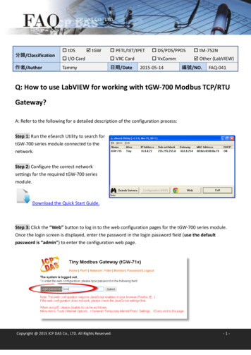
Configuration4Configuration4.1OverviewThe server can receive Modbus functions via TCP/IP.Modbus-areasThe Modbus specification defines these four Modbus-areas:Modbus-areasdigital inputs (Discrete Inputs)Data type1 BitAccessRead onlydigitale outputs (Coils)1 BitRead / writeInput registers16 BitRead onlyOutput registers16 BitRead / writeExampleAfter the installation the modbus areas are mapped to the PLC areas. Check the article about the defaultmapping [} 19].The TwinCAT Modbus TCP/IP server configurator [} 17] is used for configuring this mapping.ADS-AccessIf you want to access the specific modbus areas, you have to add these global variables to your PLC project.VAR GLOBALmb Input Coils:ARRAY [0.255] OF BOOL;mb Output Coils :ARRAY [0.255] OF BOOL;mb Input Registers :ARRAY [0.255] OF WORD;mb Output Registers :ARRAY [0.255] OF WORD;END VARRequirementsDevelopment environmentTwinCAT v3.0.04.2Target system typePC or CX (x86)PLC libraries to be linkedTc2 ModbusSrvTwinCAT Modbus TCP ConfiguratorThe configurator is installed per default to the directory \TwinCAT3\Functions\TF6250-Modbus-TCP. Thetools allow to read and change the actual configuration of TwinCAT Modbus TCP server.TF6250Version: 1.617
ConfigurationIP Address: IP of the server. If no address is set, the local one is used (default) .Port: Configured port of the server (default port 502).Get Configuration: Read configured IP address and port.Set Configuration: Set IP address and port.Export Configuration: Read and save configuration.Import Configuration: Import new configuration.Set Default Configuration: Reset to default-settings (use local ip, Port 502, and default mapping [} 19]).TwinCAT must be stopped if you want to use the configurator, which will be done by the tool.Export configurationThe configuration is XML-based and can be changed by a text editor. With "Export Configuration" the actualconfiguration can be stored local as XML-file.It is easier to edit and activate an exported configuration.Import Mapping-InformationsWith "Import Configuration" a changed configuration can be imported and activated.It is possible to map by variablename or IndexGroup/Offset (better performance).Windows CEThe standard configuration is in the TcModbusSrv.xml (path: \TwinCAT3\Functions\TF6250-ModbusTCP\Server). If you change the settings in the file, a restart is necessary.18Version: 1.6TF6250
Configuration4.3Default ConfigurationThe default mapping is shown in the following table:Modbus areasDigital inputsModbus address0x8000 - 0x80FFDigital outputs (coils)0x8000 - 0x80FFInput registers0x8000 - 0x80FFOutput registers0x3000 - 0x5FFF0x6000 - 0x7FFF0x8000 - 0x80FFADS areaName of the variables in Data typethe PLC programGVL.mb Input CoilsARRAY [0.255] OFBOOLName of the variables in Data typethe PLC programGVL.mb Output CoilsARRAY [0.255] OFBOOLName of the variables in Data typethe PLC programGVL.mb Input Registers ARRAY [0.255] OFWORD0x4020 - PLC memory0x0area0x4040 - PLC data areaName of the variables inthe PLC programGVL.mb Output Registers0x0Data typeARRAY [0.255] OFWORDThe server maps the individuals ADS areas and enables the access to the physical process image and mapsthe PLC data area.The mapping can be adjusted by the TwinCAT Modbus TCP Configurator [} 17].TF6250Version: 1.619
Diagnosis5Diagnosis5.1Modbus ADS Diagnosis InterfaceModbus ADS diagnosis interfaceVia ADS the following information can be monitored:AMSNetID: AMSNetID of the system. If the local system is used leave empty.Port: 10500 (AMSPORT R3 MODBUSSERV)ADSRead: see ADSREAD in the manual TwinCAT 3 PLC Lib: Tc2 Systemindex indexgroup offset0x2000 0access data type descriptionADSReadUINT320x2000 1ADSReadADSReadUINT320x2000 220UINT32GetConnectedClientCountreturns the number of connected ModbusclientsGetModbusRequestCountreturns the received Modbus requestsGetModbusResponseCountreturns the received Modbus answersVersion: 1.6minimal Modbusserver version1.0.501.0.501.0.50TF6250
PLC libraries6PLC libraries6.1OverviewThe defined modbus functions are implemented in the PLC library TcModbusSrv.lib.Modbus TCP functionRead CoilsFunction code1PLC blockRead Inputs2FB MBReadInputs [} 23]Read Registers3FB MBReadRegs [} 25]Read Input Registers4FB MBReadInputRegs [} 27]Write Single Coil5FB MBWriteSingleCoil [} 29]Write Single Register6FB MBWriteSingleReg [} 31]Write Multiple Coils15FB MBWriteCoils [} 32]Write Multiple Registers16FB MBWriteRegs [} 34]Read/Write Multiple Registers23FB MBReadWriteRegs [} 36]Diagnostic8FB MBDiagnose [} 38]Target system typePC or CX (x86)PLC libraries to be linkedTc2 ModbusSrvFB MBReadCoils [} 21]RequirementsDevelopment environmentTwinCAT v3.0.06.2Function blocks6.2.1FB MBReadCoils (Modbus function 1)This function is used for reading 1 to 2048 digital outputs (coils). One digital output corresponds to one bit ofthe read data bytes.VAR INPUTVAR ::::STRING(15);UINT: MODBUS TCP PORT;BYTE: 16#FF;WORD;WORD;Version: 1.621
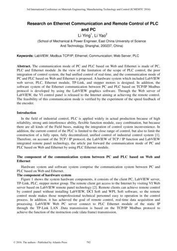
PLC librariescbLengthpDestAddrbExecutetTimeoutEND VAR::::UDINT;POINTER OF BYTE;BOOL;TIME;sIPAddr : Is a string containing the IP address of the target device.nTCPPort : Port number of the target device.nUnitID: Identification number of a serial sub-network device. If a device is addressed directly via TCP/IP,this value must be 16#FF.nQuantity : Number of digital inputs (data bits) to be read. The value of nQuantity must be 0.nMBAddr : Start address of the digital inputs to be read (bit offset).cbLength : Contains the max. byte size of the destination buffer into which the data are to be read. Theminimum buffer byte size must be: (nQuantity 7) / 8.pDestAddr : Contains the address of the destination buffer into which the data are to be read. The buffercan be a single variable, an array or a structure, whose address can be found with the ADR operator.bExecute: The function block is activated by a rising edge at this input.tTimeout: States the length of the timeout that may not be exceeded by execution of the ADS command.VAR OUTPUTVAR OUTPUTbBUSYbErrornErrIdcbReadEND VAR::::BOOL;BOOL;UDINT;UDINT;bBusy : When the function block is activated this output is set. It remains set until an acknowledgement isreceived.bError : If an ADS error should occur during the transfer of the command, then this output is set once thebBusy output is reset.nErrId : Supplies the ADS error number [} 56] when the bError output is set.cbRead: Contains the number of bytes currently read.Function specific ADS error code0x80010x80020x80030x8004Possible reasonModbus function not implementedInvalid address or lengthInvalid parameters: - wrong number of registersModbus server errorExample of calling the block in FBD:PROGRAM BAddrarrDataEND VAR22:::::::::FB MBReadCoils;BOOL;BOOL;BOOL;UDINT;UDINT;WORD : 10;WORD : 5;ARRAY [1.2] OF BYTE;Version: 1.6TF6250
PLC librariesAfter a rising edge of "bExecute" and successful execution of the ReadCoils command, the content of digitaloutputs 6 - 15 is written into the arrData array:Digital outputs6-13Array offset114-152Status0x54 The status of output 13 is theMSB of this byte (left)The status of output 6 is the LSB ofthis byte (right)0x02 Since only 10 outputs are tobe read, the remaining bits (3-8)are set to 0.RequirementsDevelopment environmentTwinCAT v3.0.06.2.2Target system typePC or CX (x86)PLC libraries to be linkedTc2 ModbusSrvFB MBReadInputs (Modbus function 2)This function is used for reading 1 to 2048 digital inputs. One digital input corresponds to one bit of the readdata bytes.VAR INPUTVAR hTF6250::::::STRING(15);UINT: MODBUS TCP PORT;BYTE: 16#FF;WORD;WORD;UDINT;Version: 1.623
PLC librariespDestAddrbExecutetTimeoutEND VAR: POINTER OF BYTE;: BOOL;: TIME;sIPAddr: Is a string containing the IP address of the target device.nTCPPort: Port number of the target device.nUnitID: Identification number of a serial sub-network device. If a device is addressed directly via TCP/IP,this value must be 16#FF.nQuantity: Number of digital inputs (data bits) to be read. The value of nQuantity must be 0.nMBAddr: Start address of the digital inputs to be read (bit offset).cbLength: Contains the max. byte size of the destination buffer. The minimum buffer byte size must be:(nQuantity 7) / 8.pDestAddr: Contains the address of the destination buffer into which the data are to be read. The buffer canbe a single variable, an array or a structure, whose address can be found with the ADR operator.bExecute: The function block is activated by a rising edge at this input.tTimeout: States the length of the timeout that may not be exceeded by execution of the ADS command.VAR OUTPUTVAR OUTPUTbBUSYbErrornErrIdcbReadEND VAR::::BOOL;BOOL;UDINT;UDINT;bBusy : When the function block is activated this output is set. It remains set until an acknowledgement isreceived.bError : If an ADS error should occur during the transfer of the command, then this output is set once thebBusy output is reset.nErrId : Supplies the ADS error number [} 56] when the bError output is set.cbRead: Contains the number of bytes currently read.Function specific ADS error code0x80010x80020x80030x8004Possible reasonModbus function not implementedInvalid address or lengthInvalid parameters: - wrong number of registersModbus server errorExample of calling the block in FBD:PROGRAM titynMBAddrarrDataEND VAR24:::::::::FB MBReadInputs;BOOL;BOOL;BOOL;UDINT;UDINT;WORD : 20;WORD : 29;ARRAY [1.3] OF BYTE;Version: 1.6TF6250
PLC librariesAfter a rising edge of "bExecute" and successful execution of the ReadInputs command, the content of digitalinputs 30 - 49 is written into the arrData array:Digital outputs29-36Array offset137-44245-493Status0x34 The status of inputs 36 is theMSB of this byte (left)The status of inputs 29 is the LSBof this byte (right)0x56 The status of inputs 44 is theMSB of this byte (left)The status of inputs 37 is the LSBof this byte (right)0x07 Since only 20 outputs are tobe read, the remaining bits (5-8)are set to 0.RequirementsDevelopment environmentTwinCAT v3.0.06.2.3Target system typePC or CX (x86)PLC libraries to be linkedTc2 ModbusSrvFB MBReadRegs (Modbus function 3)This function is used for reading 1 to 128 output registers (16 bit). The first byte contains the lower eight bitsand the second byte the upper eight bits.VAR INPUTVAR INPUTsIPAddrnTCPPortnUnitIDTF6250: STRING(15);: UINT: MODBUS TCP PORT;: BYTE: 16#FF;Version: 1.625
PLC tTimeoutEND VAR::::::WORD;WORD;UDINT;POINTER OF BYTE;BOO
The TwinCAT Modbus TCP server enables to communicate over a network connection (TCP/IP) with the Modbus protocol. Modbus is an open standard in industrial communication which will be maintained by the independent Modbus Organization. The protocol is based on a client/server-architecture. Therefore the product can be used as client or as server: