Transcription
Installation and Instructions2Product Features3-6Key Pad Functions7Distributor Information Programming Guide8Master Programming Guide9-14Dimensional Drawing15D-STC & D-SMM Valve Assembly16-17D-FTC Valve Body Assembly18-19D-STC & D-SMM Valve Body Assembly20-22D-SMM Meter Assembly23D-STC & D-SMM Wiring Diagram24Troubleshooting25Contact Information26
Water Pressure: A minimum of 20 psi inlet water pressure is required for effective regeneration.Electrical Facilities: An uninterrupted alternating current (AC) supply is required. Please make sure your voltage supply iscompatible with your unit before installation.Existing Plumbing: Condition of existing plumbing should be free from lime and iron buildup. Piping that has heavy buildup withlime and/or iron should be replaced. If piping is clogged with iron, a separate iron filter unit should be installed ahead of the watersoftener.Location of Softener and Drain: The softener should be located close to a clean working drain and connected according to localplumbing codes.Bypass Valves: Always provide for the installation of a bypass valve if unit is not equipped with one.Water pressure is not to exceed 120 psi, watertemperature is not to exceed 110 F, and the unitcannot be subjected to freezing conditions.Installation Instructions1. Place the softener tank where you want to install the unit, making sure the tank is level and on a firm base.2. All plumbing should be done in accordance with local plumbing codes. The pipe size for the drain line should be a minimum of½”. Backwash flow rates in excess of 7gpm or length in excess of 20’ require ¾” drain line.3. The 1” distributor tube (1.05 O.D) should be cut flush with top of tank.4. Pre-lubricate the distributor o-ring seal and tank o-ring seal. Twist the valve on to the tank. If applicable, pre-lubricate the plasticbypass o-ring seals and inside the plastic yoke before attaching to valve. Silicone lubricant is the only lubrication recommended.5. Solder joints near the drain must be done prior to connecting the Drain Line Flow Control fitting (DLFC). Leave at least 6”between the DLFC and solder joints when soldering pipes that are connected on the DLFC. Failure to do this could causeinterior damage to the DLFC.6. Teflon tape is the only sealant to be used on the drain fitting.7. Make sure that the floor is clean beneath the salt storage tank and that it is level.8. On units with a bypass, place in bypass position. Turn on the main water supply. Open a cold soft water tap nearby and letrun a few minutes or until the system is free from foreign material that may have resulted from the installation. Once clean,close the water tap.9. Place the bypass in service position and let water flow into mineral tank. When water flow stops, slowly open a cold water tapnearby and let run until the air is purged from the unit.10. Plug unit into an electrical outlet.Note: All electrical connections must be connected according to local codes.11. Add 7 inches of water to brine tank to cover air check on float. Manually step the valve to the Brine Draw position and allowthe valve to draw water from the brine tank until it stops.Note: The air check will check at approximately the midpoint of the screened intake area.12. Next, manually step the valve to the Brine Refill position and allow the valve to return to Service automatically.13. With the valve in Service, check that there is about 1.0” of water above the grid in the brine tank, if used.14. Fill the brine tank with salt.15. Set-up is now finished; the control can now be left to run automatically.
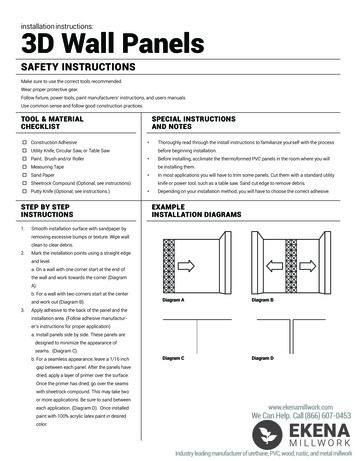
In Service DisplayTimed Regeneration Mode:The display will show the current time, day of the week,and remaining time until the next set regeneration.Meter Immediate Regeneration Mode:The display will show the current time, day of the week, andamount of treated water remaining until next regeneration.Meter Delay Regeneration Mode:The display will show the current time, day of the week,and amount of remaining treated water. At zero the displaychanges to the regeneration time set by the user.Weekly Regeneration Mode:The display will show the current time, day of the week,and the remaining time until the next set regeneration.Current Time-HoursCurrent Time-MinutesAM/PMDay of the WeekTime Remaining Until Next RegenerationValve StageMeter Icon-Rotates When Meter is OperationalRemaining Amount of Treated Water Left Prior to RegenerationVolume UnitMeter Delay Activated IconDay of Week for Next Regeneration
Automatic Keypad LockIf the keypad is not used for 3 minutes, the keyboard will be locked. To release, press any key to illuminate the screen, thenpress thebutton and then thebutton.Memory During Power FailureAll program settings are stored in permanent memory. Current valve position, cycle step elapsed, and time of day arestored during a power failure. Reset of current time is necessary when powering up.If the valve stopped at a regeneration stage during a power outage. The valve will begin at the prior position before theoutage occurred. It takes 4-5 minutes to reset to the position.Restore Factory SettingsPress and hold theRelease thebutton. The following screen displays.button. The valve has restored the factory default settings.Fault AlarmThe system will automatically detect errors. If an error is found the following screen displays.In this state, please cut off the power supply and then re-apply the power. If the errors are removed the valve will either stopin service position or reset. If conditions persist, contact your local supplier for more assistance.No Hard Water BypassThe D-Series valves are designed with the option of a no hard water bypass piston, which ensures no hard water out of theoutlet in the process of regeneration.
Manual RegenerationQueuing a RegenerationThe system will initiate regeneration at the time set that same day. If set time has passed, the system will initiateregeneration that same time the next day.When the valve is in service position press the “Manual Regen” button. The “Que Reg” icon will flash indicatingregeneration has been queued. To cancel the queued regeneration press the “manual Regen” button again.In the mode of TIME or WEEK, the display showsfor the queued regeneration.Current Time-HoursCurrent Time-MinutesAM/PMDay of the WeekTime Remaining Until Next RegenerationIcon of Queuing RegenerationValve Working StatusIn the mode of METER DELAY, the display showsthe queue for regeneration.In the mode of METER IMMEDIATE, the displayshows the queue for regeneration. The system willinitiate a regeneration either the treated waterremaining counts down to zero or the remainingtime counts down to zero, whichever is first.
Regenerating ImmediatelyWhen the valve is in service position press and hold theadvances to the stage of regeneration.button for 5 seconds. The valve immediatelyCurrent Time“GO TO BackWash” FlashesWhen time counts down to zero or pressagain to advance to next stage“GO TO BrineDraw” FlashingWhen time counts down to zero or pressagain to advance to next stage“GO TO RapidRinse” FlashingWhen Time counts down to zero or pressagain to advance to next stage“GO TO ReFill” FlashingWhen time counts down to zero or pressagain to advance to next stage“GO TO Service” Flashing
“Right Arrow” button moves the cursor to parameters for change.“Up Arrow” button increases the value of the selected parameters or confirm the selected parameters.“Time & Day” button sets the current time and day.“Mode” button selects the valve regeneration type. There are 4 mode regeneration options: Timer, Meter Immediate, MeterDelayed, and Week Day initiated regenerations.“Set Regen” button sets the appropriate requirements such as the regeneration time and water capacity for the specific modeselected.“Set Cycle” button sets the duration of Backwash, Brine Draw, Rapid Rinse, and Brine Refill.“Manual Regen” button manually initiates an immediate regeneration or a queued regeneration.
Press and hold the “Mode” button while simultaneously powering up the valve.Edit: Editing and input informationOFF: ExitMove & SelectConfirmInput distributor name and telephonenumber or email address.Total 2 linesMove the cursor right to desired position.Move cursor left to desired position.Delete character and move to next position.Move the cursor right to desired capital letter.Confirm choice.Move the cursor up or down a line.Move the cursor right to desired lower case letter.Confirm choice.Move the cursor up or down a line.Save and exit setup. If no key is pressed, the screen will time out after 10 minutes. Changeswill not be saved and display will return to service screen.Once saved this information will display alternating with the “In Service” information.Press and hold thebutton for 5 seconds to display the distributor information for 10 seconds.
Time & Day (Example: 2:30AM WED)Default SettingIncrease hour number to “02”.AM and PM change automaticallyaccording to the hours changing.Move cursor to minute number.Increase minute number to “30”.Move cursor to desired day of week.Confirm. Cursor will automaticallymove to next position.Save and Exit. If this button is not pressed within 5 minutes, changeswill not be saved and the display will return to service screen.
Mode (Example: Regeneration Type Meter Imm Unit M3)Default SettingMove cursor to desired mode.Default SettingConfirm. Cursor will automaticallymove to next position.Save and Exit. If this button is not pressed within 5 minutes, changeswill not be saved and the display will return to service screen.
Set Regen-Time Mode (Example: Time 02:30 AM Day Override 05)Default SettingMove cursor to minute number.Increase minute number to “30”.Move cursor to desired day override number.Increase day override number to “5”.Save and Exit. If this button is not pressed within 5 minutes, changeswill not be saved and the display will return to service screen.
Set Regen-Meter Imm Mode (Example: Capacity 0002000 GAL)Default SettingMove cursor to desired capacity number.Increase capacity number to “2”.Move cursor to next desired capacity number.Increase capacity number to “0”.Save and Exit. If this button is not pressed within 5 minutes, changeswill not be saved and the display will return to service screen.
Set Regen-Week Mode (Example: 02:00 AM FRI SUN)Default SettingMove cursor to defaulted day.Cancel default setting, cursor willautomatically move to next positionMove cursor to desired day.Confirm, cursor will automaticallymove to next position.Move cursor to 2nd desired day.Confirm, cursor will automaticallymove to next position.Save and Exit. If this button is not pressed within 5 minutes, changeswill not be saved and the display will return to service screen.
Set Regen-Meter Delay ModeDefault SettingUse mode of “Time” and “Meter Imm” to set.Save and Exit. If this button is not pressed within 5 minutes, changeswill not be saved and the display will return to service screen.Set CycleDefault Setting“BackWash” and “RapidRs” cannot be set to “000”.Move cursor to desired number.Increase to desired number.Save and Exit. If this button is not pressed within 5 minutes, changeswill not be saved and the display will return to service screen.
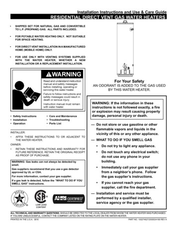
Item 122221111111111111111Part 03007021070915001750027DescriptionKeypad LabelFront CoverCircuit Board; TimerScrewScrewScrewSwitch; MicroInsulatorWire SetMain GearBrine GearTop CoverBracketGear CoverMain CamMain Cam; FilterWasherPinMotorTransformerDC SocketWiring FastenerBrine Cam; NHWBrine Cam
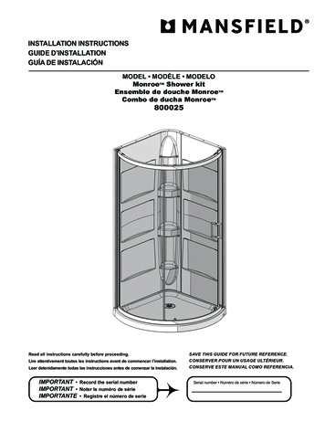
Item 111112411122111212111111Part 020100450060560800100356101DescriptionNutEnd Plug RetainerScrewPiston Joint PiecePiston Rod; FilterPiston PinScrewScrewO-RingPiston Rod RetainerPiston PinPiston; FilterSealSpacerSpacer; GasketValve Body AssemblyDrain Hose BarbO-RingDLFC Button RetainerO-RingDLFC (15 GPM)DLFC (12 GPM)DLFC (9.0 GPM)DLFC (7.0 GPM)DLFC BuckleAdaptor CouplingO-Ring1” Yoke; Plastic¾” Yoke; Plastic1 ¾” Yoke; PlasticAdaptor ClipScrewO-RingO-RingBLFC TopO-RingPlugO-RingPlugO-RingO-RingDLFC LabelO-RingPlug
Item 1111114111222111111111211Part riptionNutEnd Plug RetainerScrewPiston Joint PiecePiston Rod; FilterPiston Rod; SoftenerPiston PinScrewScrewO-RingRetainer; Piston RodPiston PinPiston; FilterPiston; SoftenerSealSpacerSpacer; EndValve Body AssemblyDrain Hose BarbO-RingDLFC Button RetainerO-RingDLFC (15 GPM)DLFC (12 GPM)DLFC (9.0 GPM)DLFC (7.0 GPM)Retainer; DrainBLFC LabelO-Ring1” Yoke; Plastic¾” Yoke; Plastic1 ¾” Yoke; PlasticAdaptor CouplingClip; MountingScrewO-RingO-RingRetainer; BLFC ButtonBLFC (1.0 GPM)BLFC (0.25 GPM)BLFC (0.50 GPM)O-RingBLFC FittingCap; InjectorO-RingVortex GeneratorPlug; Injector
Item 21111111111111111111Part r Nozzle (#4)Injector Nozzle (#0)Injector Nozzle (#1)Injector Nozzle (#2)Injector Nozzle (#3)O-RingInjector Throat (#4)Injector Throat (#0)Injector Throat (#1)Injector Throat (#2)Injector Throat (#3)O-RingScreen InjectorDLFC LabelO-RingBrine Valve SpacerO-RingBrine Valve CapSpring; Brine ValveBrine Valve SeatBrine Valve StemWasher; Brine ValveRetaining RingBypass PistonO-Ring
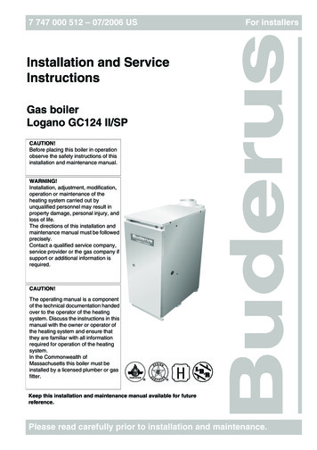
Item No.123456Quantity114122Part No.5601350022-1010131220E5004402105DescriptionFlow StraightenerMeter Cable AssemblyO-Ring; Meter BodyMeter AssemblyAdaptor ClipScrew; Adaptor Clip
Symptom1. Softener Fails to regenerateautomatically.2. Regenerating at wrong time.3. Loss of capacity.Probable CauseA. Cord plugged into intermittent ordead power source.B. Disconnected meter cable.C. Defective power cord.D. Defective timer, meter, or sensor.A. Timer improperly set due topower failure.A. Increased raw water hardness.B. Brine concentration and/orquality.C. Contaminated resinD. Poor distribution, Channeling(uneven bed surface)E. Interval valve leak.F. Resin age.G. Resin loss4. Poor water quality.A. Check items in #3.B. Bypass valve open.C. Channeling.5. High salt usage.A. High salt setting.B. Excessive water in brine tank.A. Scaling/buildup of inlet pipe.B. Contaminated resinC. Improper backwash.6. Loss of water pressure.7. Excessive water in brine tankand/or salty water to service.8. Softener fails to use salt.A. Plugged drain line.B. Dirty or damaged brine valve.C. Plugged injector.D. Low inlet pressure.E. Timer not cycling.A. Plugged/restricted drain line.B. Injector plugged.C. No water in brine tank.D. Water pressure is too low.E. Brine line injects air during brinedraw.F. Internal control leak.9. Control cycles continuously.10. Continuous flow to drain.A. Faulty timer.A. Foreign material in control.B. Internal control leak.C. Valve jammed in brine orbackwash position.D. Timer motor stopped or jammed.CorrectionA. Connect to constant power sourceB. Reconnect cable.C. Replace cordD. Replace or repair.A. Reset timer.A. Reset unit to the new capacity.B. Keep brine tank full of salt. Clean brine tank yearly. Saltmay be bridged. If using a salt grid plate, ensure refill water isin contact.C. Call dealer, find out how to confirm it, clean resin, andprevent future fouling.D. Call dealer. Check distributors and backwash flow.E. Call dealer. Replace spacers, seals, and/or piston.F. Call dealer. Check for resin oxidation caused by chlorine. ormushy resin.G. Call dealer. Check for correct bed path, broken distributors,air or gas in bed, well gas eliminator, or loose brine line.A. Check items in #3.B. Close bypass valve.C. Check for too slow or high service flow. Check for mediafouling.A. Adjust salt setting.B. See symptom #7.A. Clean or replace pipeline. Pretreat to prevent.B. Clean the resin. Pretreat to prevent.C. Too many resin fines and or sediment. Call dealer, resetbackwash flow rate and/or adjust time.A. Check flow to drain. Clean flow control.B. Clean or replace brine valve.C. Clean injector and replace screen.D. Increase pressure to allow injector to perform properly (20psi minimum).E. Replace timer.A. Clean drain line and/or flow control.B. Clean or replace injector or screen.C. Check for restriction in BLFC. Ensure safety float is notstuck.D. Line pressure must be at least 20 psi.E. Check brine line for air leaks.F. Call dealer. Check piston, seals, and spacers for scratchesand dents.A. Replace timer.A. Call dealer. Clean valve/rebuild unit.B. Same as above.C. Same as above.D. Replace timer motor.
Thank you again for choosing this control valve for water treatment systems. Please contact yourservice professional with questions.Place contact informationhere.
Turn on the main water supply. Open a cold soft water tap nearby and let run a few minutes or until the system is free from foreign material that may have resulted from the installation. Once clean, close the water tap. 9. Place the bypass in service position and let water flow into mineral tank. When water flow stops, slowly open a cold water tap