Transcription
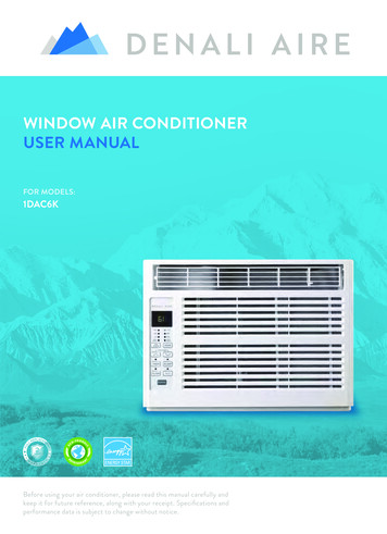
ENGLISHFRANÇAISESPAÑOLINSTALLATION MANUALAIR CONDITIONER Please read this installation manual completely before installing the product. Installation work must be performed in accordance with the national wiringstandards by authorized personnel only. Please retain this installation manual for future reference after reading itthoroughly.TYPE : Multi TypeP/NO : MFL39817319http://www.lghvac.comwww.lg.com
FLEX MULTI SPLIT INSTALLATIONINSTRUCTIONS
Multi Air Conditioner Installation ManualInstallation RequirementsInstallation Parts Provided .4Product Introduction .5Indoor Unit.5Outdoor Unit.5Safety Precautions .6Installation of Indoor, Outdoor Unit.9Select the best location .9Seaside Applications and Installation .11Piping length and elevation.12Installation.13Connecting the piping .13How To Fix .17Wiring Connection.18Conduit connection .18Ceiling dimension and hanging bolt location .19How to Fix .20Wiring Connection.20Conduit connection .20Installation of wired Remote Controller .22Wired remote controller switch information.23Trial Operation.24Celsius/Fahrenheit Switching.25Setting the Central-Control Address .26ESP Function .27Ceiling dimension and hanging bolt location .28Wiring Connection.29Conduit connection .29Installation of Wired Remote Controller(Optional) .30Installation of Decorative Panel .32Drain Piping.34Flaring Work and Connection of Piping.37Flaring work.37Connection of piping - Outdoor .38Connecting the Cable between Indoor Unit andOutdoor Unit.39Connect the cable to the Indoor unit.39Connect the cable to the Outdoor unit. .40Connection method of the connecting cable(Example) .41Checking the Drainage, Insulating the Pipe and SpecialPiping Applications .42Insulating the Pipe and Special Piping Applications .42Long Pipe Setting .43Air Purging and Evacuation .44Leak Checking .44Evacuation.45Charging .46Combination indoor units.47Required Tools Level gauge Screw driver Electric drill Hole core drill (ø50mm) Flaring tool set Specified torque wrenches1.8kg.m, 4.2kg.m, 5.5kg.m, 6.6kg.m(different depending on model No.) Adjustable wrench A glass of water Screw driver Hexagonal wrench(4mm) Refrigerant Gas Leak Detector Vacuum pump Gauge manifold Owner's manual Thermometer Remote Control HolderInstallation Manual 3ENGLISHTABLE OF CONTENTS
Installation Parts ProvidedInstallation Parts Provided[Standard / Standard Libero / Artcool Mirror]Type 1Type 2Type 3Type 4Installation plateInstallation plateInstallation plateInstallation plateType "B" screwType "B" screwType "B" screw Type "C" screwType "B" screw Type "C" screwType "A" screwType "A" screwType “A” screwType “A” screwRemote control holderRemote control holderRemote control holderRemote control holder[Cealing Concealed Duct Type]NameClamp metalInsulation forfittingScrews forduct flangesClampConduitBracketQuantity1 EA1 set1 set8 EA1 EAShapefor gas pipeConduit Bracketfor liquid pipeScrew(M4) 2EA[Cealing Cassette Type]NameDrain hoseQuantity1 EAWasher forClamp metal hanging backetShape4 Multi Air Conditioner1 EA8 EAClampConduitBracketInsulation forfittingRemotecontrol holder8 EA1 EA1 SET1 EAConduit Bracketfor gas pipeScrew(M4) 2EAfor liquid pipe
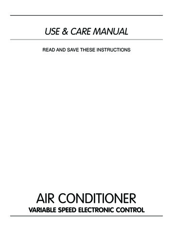
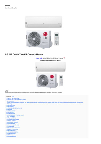
Product IntroductionHere is a brief introduction of the indoor and outdoor units. Please see the information specific toyour indoor unit type.Indoor Unit[Standard Type][Artcool Mirror Type]Air inletGrille tabPlasma filter (Optional)Air inletAir filterFront grilleON/OFF buttonPlasma filterAir dischargeAir filterSignalreceiverAir outletFront panelLouvers(Vertical blades)Flap(Horizontal blade)Power cordON/OFF buttonSignal receiver[Standard Libero Type]Air inletPlasma filterAir filterON/OFF buttonFront grilleHorizontal vaneTriple filtermore than30 cm(11.8 inch)Operation lampSignal ReceiverHorizontal vaneAir outletVertical louver Allergy free filter[Cealing Concealed Duct Type][Ceiling Cassette Type]Air Intake(side, rear)more than30 cm(11.8 inch)more than 30 cm(11.8 inch)CabinetControl coverAir DischargeConnecting wireAir InletAir outlet ventsmore than70Connection pipeDrainhoseFrontPanelSignal receivermore thanAir InletOutdoor UnitAir intake ventsConnecting wireConnection pipeDrain hoseAir outlet ventsBase plate The figure can be changed according to model.Installation Manual 5ENGLISHProduct Introduction
Safety PrecautionsSafety PrecautionsTo prevent the injury of the user or other people and property damage, the following instructionsmust be followed. Be sure to read before installing the air conditioner. Be sure to observe the cautions specified here as they include important items related to safety. Incorrect operation due to ignoring instruction will cause harm or damage. The seriousness isclassified by the following indications.WARNINGThis symbol indicates the possibility of death or serious injury.CAUTIONThis symbol indicates the possibility of injury or damage to properties only. The meanings of the symbols used in this manual are as shown below.Be sure not to do.Be sure to follow the instruction.WARNING InstallationAlways perform grounding. Otherwise, it may causeelectrical shock.Securely attach the electricalpart cover to the indoor unitand the service panel to theoutdoor unit.Donʼt use a power cord, aplug or a loose socket whichis damaged. Otherwise, it may cause a fireor electrical shock.Always install an air leakagebreaker and a dedicatedswitching board. If the electrical part cover of the No installation may cause a fireindoor unit and the serviceand electrical shock.panel of the outdoor unit are notattached securely, it could resultin a fire or electric shock due todust, water, etc.Ensure that an installation frame of theoutdoor unit is not damaged due to use for along time. It may cause injury or an accident.6 Multi Air ConditionerFor installation of the product,always contact the servicecenter or a professionalinstallation agency. Otherwise, it may cause a fire,electrical shock, explosion orinjury.Do not keep or use flammablegases or combustibles nearthe air conditioner. Otherwise, it may cause a fireor the failure of product.Do not disassemble or repair the productrandomly. It will cause a fire or electrical shock.
Safety Precautions Otherwise, it may result in personal injury.Use caution when unpacking and installing. Sharp edges may cause injury. OperationDo not share the outlet withother appliances. It will cause an electric shockor a fire due to heatgeneration.Take care so that the powercord may not be pulledduring operation. Otherwise, it may cause a fireor electrical shock.Take the power plug out ifnecessary, holding the headof the plug and do not touchit with wet hands. Otherwise, it may cause a fireor electrical shock.Do not allow water to runinto electrical parts.Do not use the damagedpower cord. Otherwise, it may cause a fireor electrical shock.Unplug the unit if strangesounds, smell, or smokecomes from it. Otherwise, it may causeelectrical shock or a fire.Do not use the power cordnear the heating tools. Otherwise, it may cause a fireand electrical shock.Hold the plug by the headwhen taking it out. Otherwise, it may cause the It may cause electric shockfailure of machine or electricaland damage.shock.Do not step on the indoor/outdoor unit anddo not put anything on it. It may cause an injury through dropping of theunit or falling down.When the product is submerged into water,always contact the service center. Otherwise, it may cause a fire or electricalshock.Do not modify or extend thepower cord randomly. Otherwise, it may cause a fireor electrical shock.Keep the flames away. Otherwise, it may cause a fire.Do not open the suctioninlet of the indoor/outdoorunit during operation. Otherwise, it may electricalshock and failure.Never touch the metal partsof the unit when removingthe filter. They are sharp and maycause injury.Do not place a heavy object on the powercord. Otherwise, it may cause a fire or electricalshock.Take care so that children may not step onthe outdoor unit. Otherwise, children may be seriously injureddue to falling down.Installation Manual 7ENGLISHDo not install the product at a place that thereis concern of falling down.
Safety PrecautionsCAUTION InstallationInstall the drain hose to ensure that draincan be securely done. Otherwise, it may cause water leakage.Always inspect gas leakage after theinstallation and repair of product. Otherwise, it may cause the failure of product.Install the product so that the noise or hotwind from the outdoor unit may not causeany damage to the neighbors. Otherwise, it may cause dispute with theneighbors.Keep level parallel in installing the product. Otherwise, it may cause vibration or waterleakage. OperationAvoid excessive cooling and performventilation sometimes.Use a soft cloth to clean. Do not use wax,thinner, or a strong detergent. Otherwise, it may do harm to your health. The appearance of the air conditioner maydeteriorate, change color, or develop surfaceflaws.Do not use an appliance for special purposessuch as preserving animals vegetables,precision machine, or art articles. Otherwise, it may damage your properties.8 Multi Air ConditionerDo not place obstacles around the flow inletor outlet. Otherwise, it may cause the failure ofappliance or an accident.
Installation of Indoor, Outdoor UnitRead completely, then follow step by step.Select the best locationIndoor unit1. Do not have any heat or steam near the unit.2. Select a place where there are no obstaclesin front of the unit.3. Make sure that condensation drainage canbe conveniently routed away.4. Do not install near a doorway.5. Ensure the unit is unobstructed, allow properspace on all sides according to the arrowsand distance measurements in the figures.6. Use a Metal Detector or Metal Scanner tolocate studs to prevent unnecessary damageto the wall.[Standard/Standard Libero/Artcool Mirror Type]More than100(3 15/16)More than 200(7 7/8)More than100(3 15/16)More than2300(90 9/16)Unit:mm(inch)[Cealing Concealed Duct Type][Cealing Cassette Type]Top view20(13/16) or moreCeilingFalse ceiling1500(59 1/16)ormoreFront viewAbove 2500(98 7/16)3300(129 15/16) or less600(23 19/32)Front1500(59 1/16)or more600(23 19/32)1000(39 3/8)False ceiling1500(59 1/16) ormoreFloor7 5/16H 13/16 or moreABCapacity(Btu/h class)AB9/12k600(23 5/8)900(35 15/32)18k600(23 5/8)1100(43 5/16)Unit:mm(inch)Installation Manual 9ENGLISHInstallation of Indoor, Outdoor Unit
Installation of Indoor, Outdoor UnitOutdoor unit1. If an awning is built over the unit to preventdirect sunlight or rain exposure, make surethat heat radiation from the condenser is notrestricted.2. Ensure the unit is unobstructed, allow properspace on all sides according to the arrowsand distance measurements in the figures.3. Do not place animals and plants in the pathof the warm air.4. Take the air conditioner weight into accountand select a place where noise and vibrationare minimum.5. Select a place so that the warm air and soundfrom the air conditioner does not disturbneighbors.more than 300(11 13/16)more than 700(27 9/16)more than 300(11 13/16)more than 600(23 21/32)Unit:mm(inch)Rooftop Installations:If the outdoor unit is installed on a roofstructure, be sure to level the unit. Ensure theroof structure and anchoring method areadequate for the unit location. Consult localcodes regarding rooftop mounting.more than 300(11 13/16)more than 300(11 13/16)Unit:mm(inch)10 Multi Air Conditioner
Installation of Indoor, Outdoor UnitENGLISHSeaside Applications and Installation1. Air conditioners should not be installed in areas where corrosive gases, such as acid or alkaline gas, areproduced.2. Do not install the product where it could be exposed to sea wind (salty wind) directly. It can resultcorrosion on the product. Corrosion, particularly on the condenser and evaporator fins, couldcause product malfunction or inefficient performance.3. If outdoor unit is installed close to the seaside, it should avoid direct exposure to the sea wind.1. Selecting the location(Outdoor Unit)1) If the outdoor unit is to be installed close to the seaside, direct exposure to the sea wind should be avoided.Install the outdoor unit on the opposite side of the sea wind direction.Sea windSea wind2) In case, to install the outdoor unit on the seaside, set up a windbreaker/barrier, to lessen the unit's exposure to sea airWindbreaker/Barrier It should be strong enough (like concrete) to obstructthe wind from the sea. The height and width should be more than 150% ofthe outdoor unit.Sea wind A minimum of 70cm (27 1/16 inches)of space between outdoor unit and the windbreakfor easy air flow.3) Select a well-drained place.Periodic ( more than once/year ) cleaning of the dust or salt particles stuck on the heat exchangerusing water is recommended.Installation Manual 11
Installation of Indoor, Outdoor UnitPiping length and elevationMulti Piping TypeUnit : m(ft)Max ElevationMax elevation Max.Combinationbetween eachbetween indoor of Indoor unitindoor unit andunits (h2)(Btu/h class)outdoor unit (h1)15(49)7.5(25)24k18kMax total lengthof all pipes(A B)/(A B C)/(A B C r UnitCapacity(Btu/h class)Max length ofeach pipe(A/B/C/D)Min length ofeach pipe(A/B/C/D)Pipe DiameterUnit : mm(inch)Indoor unitCapacity(Btu/h class)LiquidStandardPipe LengthUnit : m(ft)AdditionalRefrigerantUnit : (1/4)7.5(25)20(0.22)ABh2Ch1DCAUTION: Capacity is based on standard length and maximum allowancelength is on the basis of reliability.12 Multi Air Conditioner
InstallationENGLISHInstallation[Standard / Standard Libero / Artcool Mirror Type]Connecting the piping# Standard / Artcool Mirror Type1. Prepare the indoor unit's piping and drainhose for installation through the wall.2. Remove the plastic tubing retainer(see theillustration on the right) and pull the tubingand drain hose away from chassis.3. Route the indoor tubing and the drain hose tothe required piping hole position.4. Insert the piping, drain hose, and theconnecting cable into the piping hole.5. Insert the connecting cable into the indoor unit. Don't connect the cable to the indoor unit. Make a small loop with the cable for easyconnection later.6. Tape the tubing and drain hose.Drain pipeTapeConnectingpipeDrain hoseFor right rear piping7. Indoor unit installation Hang the indoor unit from the hooks at thetop of the installation plate. Insert the spacer etc. between the indoorunit and the installation plate and separatethe bottom of the indoor unit from the wall.For left rear pipingIndoor unitSpacerInstallation plate80(3 5/32)Installation Manual 13
Installation# Standard Libero Type1. Pull the screw cap at the bottom of the indoor unit2. Remove the chassis cover from the unit byloosing screwsChassis coverIndoor unit back side view3. Pull back the tubing holder.Pipe Port4. Remove pipe port cover and positioningthe tubingLeftRightTubing holderBackwards5. Indoor unit installation1) Hook the indoor unit onto the upper portion ofthe installation plate.( engage the threehooks at the top of the indoor unit with theupper edge of the installation plate) Ensurethat the hooks are properly seated on the installation plate by moving it left and rightInstallation plate2) Unlock the tubing holder from the chassisand mount between the chassis and installation plate in order to separate the bottom sideof the indoor unit from the wallTubing Holder14 Multi Air Conditioner
Installation1. Align the center of the pipes andsufficiently tighten the flare nut by hand.Indoor unit tubingFlare nutPipes2. Tighten the flare nut with a wrench.Open-end wrench (fixed)Outside .m (lbf·ft)1.8 2.5 (13 18)3.4 4.2 (24 30)5.5 6.6 (40 48)3. Next, extend the indoor unit's drain hose.Then attach the drain pipe.Flare nutWrenchConnection pipeIndoor unit tubingDrain pipeIndoor unit drain hoseAdhesiveVinyl tape(narrow)Installation Information. For left piping. Follow the instruction below.Good case Press on the upper side of clamp and unfold the tubing to slowly downward.Bad case Bending the pipe from right to left may cause damage to the tubing.Installation Manual 15ENGLISHConnecting the piping to the indoor unitand drain hose to drain pipe.
InstallationWrap the insulation material around theconnecting portion.1. Overlap the connection pipe insulation and theindoor unit pipe heat insulation material. Bindthem together with vinyl tape so that there is nogap.2. Wrap the area which accommodates the rearpiping housing section with vinyl tape.Plastic bands Insulation materialIndoor unit pipeConnection pipeWrap with vinyl tapeVinyl tape (wide)PipeVinyl tape(narrow)3. Bundle the piping and drain hose together bywrapping them with vinyl tape over the rangewithin which they fit into the rear piping housingsection.Vinyl tape(wide)Drain hoseReroute the pipings and the drain hose acrossthe back of the chassis.Finishing the indoor unit installation# Standard / Artcool Mirror Type1. Remove the spacer.2. Ensure that the hooks are properly seated onthe installation plate by moving it left and right.3. Press the lower left and right sides of the unitagainst the installation plate until the hooksengage into their slots(clicking sound).# Standard Libero Type1. Mount the tubing holder in the original positon.2. Ensure that the hooks are properly seated on theinstallation plate by moving it left and right.3. Press the lower left and right sides of the unitagainst the installation plate until the hooks engage into their slots (clicking sound).4. Finish the assembly by screwing the unit to theinstallation plate by using two pieces of type "C"screws. And assemble a chassis cover.16 Multi Air ConditionerPiping forpassage throughpiping holeConnectingDrain hoseType 'C' screw
InstallationENGLISHInstallation of filters1) Pull out the triple filter and allergy free filterfrom the separately packed plastic bag.2) Insert the triple filter into the left case and insert the allergy free filter into the right case.3) Detach two attached tapes from the plasmafilter.Triple FilterAllergy Free FilterPlasma FilterHow To FixThe wall you select should be strong and solid enough to prevent vibration1. Mount the installation plate on the wall withtype "A" screws. If mounting the unit on a concrete wall, use anchor bolts. Mount the installation plate horizontally by aligning the centerline using a level.2. Measure the wall and mark the centerline. It is also important to use caution concerning thelocation of the installation plate-routing of the wiring to power outlets is through the wallstypically. Drilling the hole through the wall for piping connections must be done safely.Indoor TypeStandard / Standard Libero /Artcool Mirror Type 1 Capacity (kBtu/h)9/1218TypeType 1 / Type 3Type 2 / Type 4 Type 2 Installation PlateInstallation PlateChassisHookChassisHookType “A”110(4 11/32)110(4 11/32)Type “A”90Ø70mm (3 17/32)Left rear piping70(2 3/4)Ø70mm 133mmØ70mm Type 3 100mm Ø70mmLeft rear pipingRight rear pipingRight rear piping Type 4 Installation PlateInstallation PlateType "A" ScrewsPlace a level on raised tabUnit Outline442(17.4)Type "A" ScrewsPlace a level on raised tabRight rear pipingUnit Outline442(17.4)Enganchedel chasis460(18.11)570(22.44)Enganchedel chasisØ70(2.76)Ø70(2.76)Left rear pipingInstallation )Ø70(2.76)95(3.7)217(8.5)Ø70(2.76)Installation PlateMeasuring TapeLeft rear piping69(2.72)105(4.13)Measuring ion Manual 17
InstallationWiring Connection1. Connect the wires to the terminals on thecontrol board individually according to theoutdoor unit connection. Ensure that the color of the wires of outdoorunit and the terminal No. are the same asthose of indoor unit respectively.Terminal Block in Indoor1(L1) 2(L2)34Connecting cableConnected to Outdoor Unit2. Attach the Grille onto the cabinet. Grasp the lower left and right side of theGrille and engage four tabs on the top insideedge of the chassis. Press the Grille toward the chassis until itgoes back into place.Conduit connection1. Set the connecting cable into the terminalblock of indoor unit, and tighten set screw tolock the conduit bracket to the indoor unit.2. Join the conduit and the conduit brackettogether.Lock nutConduitbracketConduitCAUTION : Must usethe elbow type (L-Type)conduit.Connecting cableViewTerminal blockConnecting cableCable retainer18 Multi Air Conditioner
InstallationENGLISH[Cealing Concealed Duct Type]Ceiling dimension and hanging bolt locationInstallation of UnitBAInstall the unit above the ceiling correctly.CASE 1CDPOSITION OF SUSPENSION BOLTGE Apply a joint-canvas between the unit and ductto absorb unnecessary vibration. Apply a filter Accessory at air return hole.Unit:mm(inch)DimensionCDEFGHI9/12k850 900 383 570 93.5 190 20.6 795 163(33 15/32) (35 15/32) (15 3/32) (22 7/16) (3 11/16) (7 1/2) (13/16) (31 5/16) (6 13/32)18k1130 1180 38357093.5 190 20.6 1065 163(44 1/2) (46 1/2) (15 3/32) (22 7/16) (3 11/16) (7 1/2) (13/16) (41 15/16) (6 13/32)IFB1/100ACapacityBtu/h classHDrainage holeCASE 2 Install the unit leaning to a drainage hole side asa figure for easy water drainage.M10 NutX4(LocalM10 SP. washer X 4 supply)M10 washerX4M10 washerPOSITION OF CONSOLE BOLT A place where the unit will be leveled and thatcan support the weight of the unit.X4(LocalM10 SP. washer X 4 supply)M10 NutX4 A place where the unit can withstand itsvibration. A place where service can be easily performed.Installation Manual 19
InstallationHow to Fix Select and mark the position for fixingbolts. Drill the hole for set anchor on the face ofceiling. Insert the set anchor and washer onto thesuspension bolts for locking thesuspension bolts on the ceiling. Mount the suspension bolts to the setanchor firmly. Secure the installation plates onto thesuspension bolts (adjust level roughly)using nuts, washers and spring washers.Old buildingNew building1 Set anchor2 Plate washer3 Spring washer4 Nut5 SuspensionboltsCAUTION : Tighten the nut and bolt to prevent unit falling.Wiring ConnectionConnect the wires to the terminals on the control board individually according to the outdoor unit connection. Ensure that the color of the wires of outdoor unit and the terminal No. are the same as those of indoor unit respectively.B1/B2 SeriesTerminal Block of Indoor Unit1(L1) 2(L2)3Connected to outdooor unitConduit connection1. Remove the busing rubber product attached on the indoor unit.2. Set the connecting cable into the terminal block of indoor unit, and tighten set screw to lock theconduit bracket to the indoor unit.3. Join the conduit and the conduit bracket together.Lock nutConduit20 Multi Air ConditionerConduitmountingplate
Installation1. Install declination of the indoor unit is very important for the drain of the duct type air conditioner.2. Minimum thickness of the insulation for the connecting pipe shall be 19mm(1/32 inch).Front of view The unit must be horizontal or declined to the drain hose connected whenfinished installation.CeilingDrainage holeDrain Pump useINSULATION, OTHERSTHERMAL INSULATIONInsulate the joint and tubes completely.All thermal insulation must comply with local requirement.INDOOR UNITUnion for gas pipeThermal insulator for refrigerant pipe(Local supply) Thermal insulator forpiping(Local supply)Refrigerant pipe and thermalinsulator(Local supply)Hose clip for thermal insulator(Local supply)Thermal insulator for refrigerant pipe(Local supply)Union for liquid pipeOverlap with thermalinsulator for piping.Hose clip for thermal insulator(Local supply)Make sure that there is no clearance here.FeltCabinetRubberInsulationNo clearanceTEST AND CHECK After all workings are finished, check the working and operation. Air distribution . Drain . Gas leakage . Wiring . Lock-bolt . Insulation. Ground .IsIsIsIsIsIsIsthethethethethethetheair circulation good?drainage smoothly and no sweating?piping connection correctly?wiring connection correctly?lock-bolt of compressor loosened?unit fully insulated?unit safely grounded?Installation Manual 21ENGLISHCAUTION
InstallationInstallation of wired Remote Controller1Put the installation paper on the place and determinethe position and height of the fixing screws of the wiredremote controller. Refer to the printed side of the installation paper.The position of the fixing screwsPlug the connecting cable into the indoor unit.CN-DISP IC01ALO1KJ14C01KJ15CN-REMORedYellow BrownMain frameSide ofIndoor UnitRemove the installation paper before installing theremote controller so that it can fit at the right place.LO1D C07DCN-M C CN-ZONE The product is being shipped with the cableconnected only to the remote controller.Fix the connecting cable with the cable rack.Side ofremote Controller3Mainindoor unitLO2K2Fixing theremote controller* Do not embed the remote controller into the wall.(It may cause the breakdown of thetemperature sensor.)20mm(25/32 inch)* If you want to install a number of remotecontroller at the same place in a vertical line,install them at regular intervals of 20mm(25/32 inch).(It may cause the breakdown of the temperature sensor.)* Do not install the cable with a distance of 50m(164ft) or longer.(This can cause communication error.)* When installing the cable, check whether the connector between the remote controller and theproduct is installed properly. The connector will not be connected when installed in oppositesides. Supply the power after connecting wired remote controller.When you need to change wired remote controller, switch off the main power and change it.If the wired remote controller is changed before switching off the main power, the option functionof the indoor unit can't be used. (option function like "slo" fan speed selection)22 Multi Air Conditioner
InstallationGroup ControlGroup control switchSWGR1. For individual control/Master use2. For group control/Slave use21Ceiling Height/Default E.S.PSWHICeiling height selection switch1. Low ceiling2. Standard ceiling3. High ceiling321S/W 1Select ProductSWPDProduct selection switch1. Cooling Only product2. Heat Pump product21Room Temp. Sensing3 2 1SWTHIndoor temperature sensor selectionswitch1. Use the temperature sensor on the remotecontroller.2. Use the temperature sensor on the product.3. Use the sensors on the product and remotecontroller. When changing the product selection switch and group control switch, the power must bereconnected to reflect the changes. The central control could operate inappropriately depends on indoor unit type, when the remotecontroller is set as slave.Installation Manual 23ENGLISHWired remote controller switch information
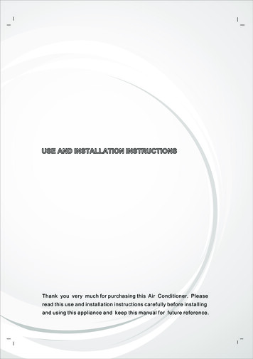
Installation Necessary functions before usingTrial OperationThe trial operation is to check the installation status of the product. The temperature will not becontrolled during trial operation. Instead the product will operate in several modes such as cooling,strong wind, comp-on.1If you want to set the trial operation mode, pressthe mode button and the Fan speed button sametime for three seconds.2Then the product will begin the trial operation andthe display will be like as shown on left sidepicture.3If you want to cancel the trial operation mode, justpress the On/Off button.4The trail operation will be shut downautomatically after 18 minutes and system will goto the standby mode.PQRCUCS0CDefrostPreheat Out doorRoom TempTotal onCentral RunTEMPMOD
www.lg.com ENGLISH FRANÇAIS ESPAÑOL. FLEX MULTI SPLIT INSTALLATION INSTRUCTIONS. Installation Manual 3 Multi Air Conditioner Installation Manual TABLE OF CONTENTS . Air. Installation Manual Installation . Installation Unit. work)