Transcription
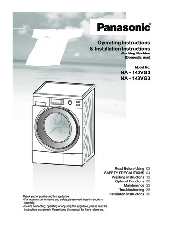
Installation Manual and Operating InstructionsPowerstar electric water heatersAE 115/1256720800414-00.1VenesfrInstallation Manual and Operating InstructionsInstrucciones de instalación y funcionamientoInstructions d'installation et d'utilisation227536 720 800 414 (2011/09) USIMPORTANT: This booklet should be given to the customer after installation and demonstration.For Service & Installation contact:BOSCH Thermotechnology Corp.50 Wentworth Avenue, LondonderryNH 03053Phone: 866-330-2729www.bosch-climate.us
Table of contentsTable of contents1Explanation of symbols and safety information 31.1Explanation of symbols . . . . . . . . . . . . . . . 31.2Safety precautions . . . . . . . . . . . . . . . . . . 32General information . . . . . . . . . . . . . . . . . . . . . .2.1Disclaimer . . . . . . . . . . . . . . . . . . . . . . . . .2.1.1 Approval number . . . . . . . . . . . . . . . . . . . .2.2Technical identification code . . . . . . . . . .2.3Model name and number identification . .2.4Package contents . . . . . . . . . . . . . . . . . . .2.5Components Diagram . . . . . . . . . . . . . . . .2.6Dimensions . . . . . . . . . . . . . . . . . . . . . . . .2.7Wiring diagram . . . . . . . . . . . . . . . . . . . . .2.8Function . . . . . . . . . . . . . . . . . . . . . . . . . .2.9Technical specifications . . . . . . . . . . . . . .3Regulations . . . . . . . . . . . . . . . . . . . . . . . . . . . . 104Installation . . . . . . . . . . . . . . . . . . . . . . . . . . . . 114.1Important information . . . . . . . . . . . . . . . 114.2Selection of place of installation . . . . . . . 114.2.1 Freeze prevention . . . . . . . . . . . . . . . . . . 114.2.2 Recommended minimum clearancesfor servicing . . . . . . . . . . . . . . . . . . . . . . . 124.3Mounting the water heater . . . . . . . . . . . 124.4Water connections . . . . . . . . . . . . . . . . . 134.4.1 Water quality . . . . . . . . . . . . . . . . . . . . . . 134.5Electrical connections . . . . . . . . . . . . . . . 134.6Starting up . . . . . . . . . . . . . . . . . . . . . . . 174.6.1 Checking for leaks and purging air . . . . . 174.6.2 Adjusting the temperature dial . . . . . . . . 174.6.3 Adjusting the flow . . . . . . . . . . . . . . . . . . 175Operation instructions . . . . . . . . . . . . . . . . . . . 185.1Before using the water heater . . . . . . . . . 186Maintenance . . . . . . . . . . . . . . . . . . . . . . . . . . . 197Troubleshooting . . . . . . . . . . . . . . . . . . . . . . . . 218Spare Parts . . . . . . . . . . . . . . . . . . . . . . . . . . . . 252555555567896 720 800 414 (2011/09)
Explanation of symbols and safety information1Explanation of symbols and safety information1.1Explanation of symbolsWarningsWarnings are indicated in the text by awarning triangle and a gray background.1.2Safety precautionsWhen using this electrical equipment, basic safetyprecautions should always be followed, including thefollowing:B READ AND FOLLOW ALL INSTRUCTIONS.B This appliance must be grounded.In case of danger due to electric shock, theexclamation point on the warning triangle isreplaced with a lightning symbol.Signal words at the beginning of a warning are used toindicate the type and seriousness of the ensuing risk ifmeasures for minimizing damage are not taken.B Disconnect this product from the electrical supplybefore cleaning, servicing or removing the cover.B To reduce the risk of injury, close supervision isnecessary when the product is used near children orelderly persons. NOTE indicates possible minor to medium personalinjury.B Warning: Mount the unit onto a flat section of wall,well away from any potential splashes of water orspray and away from areas where direct moist or wetcontact could occur. CAUTION indicates possible minor to mediumpersonal injury.B Warning: Indoor installation only, where it will NOT beexposed to freezing. WARNING indicates possible severe personal injury. DANGER indicates that severe personal injury mayoccur.B Warning: Do not install a check valve or any other typeof back flow preventer within ten feet of the coldwater inlet.Important informationB The electrical installation must conform to currentNational Electrical Codes.Important information that presents no riskto people or property is indicated with thissymbol. It is separated by horizontal linesabove and below the text.Additional symbolsSymbolMeaningBa step in an action sequence a reference to a related part in thedocument or to other related documents a list entry–a list entry (second level)Tab. 1B Warning: Do not switch the heater on if you suspectthat it may be frozen. Wait until you are sure that ithas completely thawed out.B The Powerstar electric water heater is designed toheat potable cold water for domestic purposes. Theheater is not designed to accept inlet watertemperatures above 86 F. Contact BoschThermotechnology Corp. before specifying orinstalling the appliance in any other application.B Warning: Any water heater should be installed in sucha manner that if it should leak, the resulting flow ofwater will not cause damage to the area in which it isinstalled. National Plumbing codes require a drain panfor any water heater installation. Failure to install oneis the sole responsibility of owner and/or installer.Reference UPC 2000 (Uniform Plumbing Code)Section 510 - Protection from Damage or IPC 200(International Plumbing Code) Section 504- SafetyDevices.B Additional Canadian safety instructions:– As per the Canadian Electrical Code, C22.1-02Section 26-744, an auxiliary terminal block must befitted to the unit before connecting to the electricalsupply (Kit Part N “AE Canada Kit”).(See Page 16).– A green terminal (or a wire connector marked “G,”“GR,” “GROUND” or “GROUNDING”) is provided6 720 800 414 (2011/09)3
Explanation of symbols and safety informationwithin the control. To reduce the risk of electricalshock, connect this terminal or connector to thegrounding terminal of the electrical service ofsupply panel with a continuous copper wire inaccordance with the Canadian Electrical Code,Part I.– This product shall be protected by a Class A groundfault circuit interrupter.B Keep this manual in a safe place once the unit hasbeen installed as it may be needed for futurereference.46 720 800 414 (2011/09)
General information2General information2.1Disclaimer2.1.1Approval number2.3Commonwealth of MassachusettsIn the Commonwealth of Massachusetts a licensedplumber or electrician must perform the installation.(Approval number: P1-09-25).2.2Model name and numberidentificationModel NameModel NumberAE115EI 17 E/M W I H BAE125EI 27 E/M W I H BTab. 3Technical identification code2.4Package contents Tankless electric water heater.EI17E/MWIHBEI27E/MWIHB 4 screws and gasket.Tab. 2EI17E/MWIHBElectronic InstantaneousMaximum output (kW)Electronic / mechanical temperature controlWall hungIndoorHorizontal installationWater connections2.5Components DiagramBCLAIJHGDN6720646951-14.1VMEFKFig. 1ABCDEFGHeating moduleHeating element assemblyHeating module PCBHot water outletCold water inletTemperature adjustment knobFlow transducer6 720 800 414 (2011/09)HIJKLMNTerminal block (CANADA ONLY)6 way terminal blockTemperature sensorControl PCBDouble pole thermal cut-outInlet water filterFlow regulator5
General information2.6DimensionsFig. 21234Outlet ¾ " NPT (hot water)Inlet ¾ " NPT (cold water)Temperature knobLEDDimensions(inches)AE115 / AE125A (Width)15 ¼ "B (Height)12 ½ "C (Depth)4½"D12 5/8"E12 5/8"F2½"G3½"H6 1/8"I5¾"J1¾"Water connections¾"Tab. 46Dimensions6 720 800 414 (2011/09)
General information2.7Wiring diagramDANGER: Risk of electric shock!B Always switch off the electricity supply tothe unit before any intervention in theheater.6720646951-02.1VFig. 3Internal wiring schematic for single phase AE125 unit.6 720 800 414 (2011/09)7
General information6720646951-03.1VFig. 42.8Internal wiring schematic for single phase AE115 unit.FunctionHow the water heater works: The Powerstar electric water heater, heats watercontinuously as it flows through the heater modules. The electronic control PCB monitors the flow rate andthe incoming water temperature and then switcheson the required number of heater elements to reachthe temperature set by the temperature adjustmentdial. As the flow rate or the incoming water temperaturechanges, the electronic control adjusts the number ofheater elements used so that the outlet temperatureis maintained.Contact Technical Support 866-330-2729 for furtherinstruction. The AE115 unit is supplied from two independentvoltage supplies and the AE125 unit from threeindependent voltage supplies. (In Canada the unit hasjust one voltage supply). Depending on the region of the country, thetemperature of the water supply can vary between40 F in winter to 70 F in summer, with an average of55 F. The output temperature at maximum flow ofthe heater is dependent on inlet water temperature. The outlet water temperature can change slightly asthe flow rate changes due to the steps in power asdifferent heater elements are switched on and off. The outlet water temperature can also vary if themaximum flow rate is exceeded (see Fig. 11) or if thesupply voltage changes. Each heater module is protected by an electromechanical thermal cut-out. This cut-out will only tripin exceptional circumstances.86 720 800 414 (2011/09)
General information2.9Technical specificationsTechnical characteristicsUnitsAE115AE125Voltage supplyV2 X 240VAC (Canada 240VAC)3 X 240VAC (Canada 240VAC)AmperageA2 X 40A (Canada 80A)3 X 40A (Canada 120A)kW17.25kW26.85kW95 F to 131 F95 F to 131 FMaximum outputTemperature control rangeMinimum water pressurepsi15psi15psiMaximum water pressurepsi150psi150psigal/min0.6 US gal / min0.8 US gal / min(refer to Fig. 11)(refer to Fig. 11)20 lbs22 lbsMinimum flow rateMaximum flow rateWeight (without water)lbsThe unit will work at lower supply voltages but the following changes will apply:Maximum output15kW at 220V22.5kW at 220V13kW at 208V20kW at 208VMaximum power84% of maximum at 220V84% of maximum at 220V(refer to Fig. 11)75% of maximum at 208V75% of maximum at 208VTab. 56 720 800 414 (2011/09)9
Regulations3RegulationsAny local by-laws and regulations pertaining toinstallation and use of electric water heating appliancesmust be observed. Please refer to the laws that shouldbe attended in your country. The electrical installation must conform to currentNational Electrical Codes. As per the Canadian Electrical Code, C22.1-02Section 26-744, an auxiliary terminal block must befitted to the unit before connecting to the electricalsupply (Kit Part N “AE Canada Kit”). A green terminal (or wire connection marked “G”,“GR”, “GROUND” or “GROUNDING”) is providedwithin the control box. Aditional Canadian safetyinstructions, to reduce the risk of electrical shock,connect this terminal or connector to the groundingterminal of the electrical service of supply panel witha continuous copper wire in accordance with theCanadian Electrical Code, Part I. In Canada this product shall be protected by a ClassA ground fault circuit interrupter. In the Commonwealth of Massachusetts a licensedplumber or electrician must perform the installation.(Approval number: P1-09-25). In the Commonwealth of Massachusetts a pressurerelief valve shall be installed on the cold water side bya licensed plumber. (MGL 142 Section 19, Approvalnumber P1-09-25). The unit must be wired by a qualified electrician, inaccordance with the current version of the NationalElectrical Code US) or Canadian Electric Code(Canada). When the heater is not within sight of the electricalcircuit breakers, a circuit breaker lockout oradditional local means of disconnection for all nongrounded conductors must be provided that is withinsight of the appliance. (Ref NEC 422.31.). The power cable size and the installation must be inaccordance with the Canadian Electrical Code, C22.102.WARNING:California Proposition 65 lists chemicalsubstances known to the state to causecancer, birth defects, death, serious illnessor other reproductive harm. This productmay contain such substances, be theirorigin from fuel combustion (gas, oil) orcomponents of the product itself.106 720 800 414 (2011/09)
Installation4InstallationDANGER: Risk of electric shock!4.2B For safety reasons, disconnect the powersupply to the heater before any service ortesting is performed.WARNING: Risk of freezing!B Do not install the water heater in an areawhere there is a chance of freezing.Damage to the water heater as a result offreezing will not be covered underwarranty.WARNING:B This heater must be electrically groundedin accordance with the most recentedition of the National Electrical Code.NFPA 70. In Canada, all electrical wiringto the heater must be in accordance withlocal codes and the Canadian ElectricalCode, CSA C22.1 Part 1.4.1Important informationDANGER:B The installation must only be performedby a qualified person in accordance withthese instructions.B Bosch Thermotechnology Corp. is notresponsible for improperly installedappliances.WARNING:B The heater must only be mounted in avertical position with the water fittingslocated at the bottom of the heater.Under no circumstances should theheater be mounted differently.WARNING:B The appliance should be located in anarea where leakage of the heater orconnections will not result in damage tothe area adjacent to the appliance or tolower floors of the structure.Please follow these instructions. Failure to followinstructions may result in: Damage or injury.Selection of place of installation If being used in a public place, locate the heater outof easy reach to discourage vandalism. Mount the unit onto a flat section of wall, well awayfrom any potential splashes of water or spray andaway from areas where direct moist or wet contactcould occur. Install the heater in a place that provides easy accessfor any service or maintenace.4.2.1Freeze preventionWARNING:B ELECTRICITY IS EXTREMELYDANGEROUS. TAKE EXTRAPRECAUTIONS AND ENSURE ALLCIRCUIT BREAKERS ARE OFF BEFOREPERFORMING ANY WORK TO THEHEATER.WARNING:B Indoor installation only, where it will NOTbe exposed to freezing.IntroductionPlease note that the water heater must not be installedin a location where it may be exposed to freezingtemperatures. If the heater must be left in a space thatis likely to experience freezing temperatures, all watermust be drained from the heater. See Section 6.Freeze damage is not covered under the warranty.Use of chemical agents such as anti-freezeare not allowed as they may cause damageto the water heater’s internal components. Improper installation/operation. Loss of warranty.6 720 800 414 (2011/09)11
Installation4.2.2Recommended minimum clearances forservicing4.3Mounting the water heaterWARNING:Should it be necessary to service the Powerstar electricwater heater, observe the following clearances. Theseare not required clearances, but would facilitate anyservice work.B The heater must only be installed in theorientation shown in Fig. 6 i.e., mountedin a vertical position with the waterfittings located at the bottom of theheater. Under no circumstances shouldthe heater be mounted differently.B Undo the retaining screws on the front cover and takethe cover off the heater. Hold the back plate inposition against the wall and mark the four mountingholes.B Drill the holes and secure the heater using the fourwood screws supplied.Fig. 5Recommended minimum clearancesAE115AE12512"12"Sides0"0"Bottom (B)6"6"12"12"Top (A)Front (C)Tab. 612Fig. 6Vertical mounting positionRecommended minimum clearances6 720 800 414 (2011/09)
Installation4.4Water connectionsWARNING:B Do not install a non-return check valvewithin 10 feet of the inlet.WARNING:B Do not apply heat or solder toconnections or pipe if they are alreadyconnected to the unit.4.4.1Water qualityWater quality can have an impact on appliance longevityand may not be covered under the manufacturer'swarranty.B For water analysis data call your local waterdepartment, or if on a well, have well water analyzedperiodically.If water quality exceeds one or more of the valuesspecified below, Bosch recommends consulting alocal water treatment professional for watersoftening/conditioning options.NOTICE: DisclaimerB In the Commonwealth of Massachusettsa pressure relief valve shall be installedon the cold water side by a licensedplumber. (MGL 142 Section 19, Approvalnumber P1-09-25).B The heater must be connected directly to the maincold water supply and not to pre-heated water. (Theinlet water temperature must not be greater than86 F).B The heater must be installed with shutoff valves onboth the inlet and outlet connections.B It is recommended that you use ¾ inch or ½ inchcopper or high-pressure flex connections.B Do not use plastic piping within 3 feet on either sideof heater.B Use Teflon tape for sealing pipe threads. Do NOT usepipe dope.B Remember to keep the hot water pipe runs as shortas possible.After the heater has been plumbed, and before youwire it, flush it with water to remove any debris orloose particles. Heater must be full of water and airpurged before power is turned on. Failure to do somay result in damage to the product that is notcovered by warranty.B After flushing and filling the heater with water, (withpower off) disconnect the inlet connection andinspect the filter screen for any debris that may havebeen flushed through the system.The inlet and outlet connections are clearlymarked on the heater. They each have a¾ inch NPT connector.DescriptionMax. LevelspHpH6.5 - 8.5TDS (total DissolvedSolids)mg/l or ppm500Total hardnessmg/l or ppm100Aluminummg/l or ppm2.0Chloridesmg/l or ppm250Coppermg/l or ppm1.0Ironmg/l or ppm0.3Manganesemg/l or ppm0.05Zincmg/l or ppm5.0Tab. 74.5Electrical connectionsWARNING:B The unit must be wired by a qualifiedelectrician, in accordance with thecurrent version of the National ElectricalCode US) or Canadian Electric Code(Canada).When the heater is not within sight of theelectrical circuit breakers, a circuit breakerlockout or additional local means ofdisconnection for all non-groundedconductors must be provided that is withinsight of the appliance. (Ref NEC 422.31.).B Check the pressure of the main water supply. Tooperate correctly, the heater needs the runningpressures mentioned in Tab. 5.6 720 800 414 (2011/09)13
InstallationAs per the Canadian Electrical Code, C22.102 Section 26-744, an auxiliary terminalblock must be fitted to the heater beforeconnecting to the electrical supply. This isavailable as a kit from BoschThermotechnology Corp. Part Number “AECanada Kit”. (Contact 866-330-2729).US wiring The minimum recommended wire size is 8 AWG. (Theterminal block will accept cables up to 6 AWG size). The cable entry is via the 1¼ inch cable entry hole onthe bottom right hand edge of the back plate. Strip back the insulation on the power wires about½ inch. Connect the live wires to the terminalsmarked “L1” and “L2.” There are two pairs of livewires in the AE115 and three pairs of live wires in theAE125. (See Fig. 7 and Fig. 8, page 15). Any insulation on the ground wires should be strippedback about ¾ inch. The ground leads must beconnected to the pillar terminal marked “GR”. (SeeFig. 7 and Fig. 8, page 15). Make sure the terminal block screws are tightenedsecurely. Loose connections can cause wires to heatup. Make sure that the ground wires are wrapped aroundits terminal stud and into the saddle washer. The nutshould be tightened securely. Attach the front cover and tighten the retainingscrews.146 720 800 414 (2011/09)
InstallationThe AE115 requires two independent 240V AC circuits protected by two separate and independent double polebreakers (as shown) rated at 40A each.Fig. 7AE115 terminal block connection (U.S.A. only)The AE125 requires three independent 240V AC circuits protected by three separate and independent double polebreakers (as shown) rated at 40A each.Fig. 8AE125 terminal block connection (U.S.A. only)6 720 800 414 (2011/09)15
InstallationCanada Wiring - auxiliary terminal block andconnectionsFitting the auxiliary terminal block (see diagram below).Connecting the supply cable - Canada only - not for theUSA.The AE115 requires an 80A 240V ACsingle phase supply protected by an 80Adouble pole circuit breaker.The AE125 requires a 120A 240V ACsingle phase supply protected by a 120Adouble pole circuit breaker. The power cable size and the installation must be inaccordance with the Canadian Electrical Code, C22.102. The incoming hole diameter on auxiliary terminalblock can accept up to 1/0 AWG size cables. The cable entry is via the 1 ¼ inch cable entry hole onthe bottom right hand edge of the backplate.Fig. 9For Canada only (Not for U.S.A.) Strip back the insulation on the power wires about½ inch. Connect the ungrounded conductors to theterminals “L1” and “L2” on the auxiliary terminalblock. Any insulation on the ground wire should be strippedback about ¾ inch. The ground lead must beconnected to the pillar terminal marked “GR.” Make sure the terminal block screws are tightenedsecurely. Loose connections can cause wires to heatup. Make sure that the ground wire is wrapped around itsterminal stud and into the saddle washer. The nutshould be tightened securely. Attach the front cover and tighten the retainingscrews.Fig. 10 For Canada only (Not for U.S.A.)B Connect the red wires from the left hand terminal ofthe new block to the L1 terminals in the unit. (Thereare two red wires required in the AE115 and three inthe AE125).B Connect the blue wires from the right hand terminalof the new block to the L2 terminals in the unit.(There are two blue wires required in the AE115 andthree in the AE125).B Push and click the auxiliary terminal block onto thelouvered rail in the backplate.166 720 800 414 (2011/09)
Installation4.64.6.1Starting up4.6.2Checking for leaks and purging airB Verify all circuit breakers supplying power to thewater heater are turned off.B Open all hot water taps supplied by the water heaterand inspect all water connections for leaks.B With all hot water taps still open, inspect each tap toensure all air in the lines has been purged out.B With the air purged and taps still flowing, turn on allcircuit breakers supplying the water heater.B Close all hot water taps and proceed to the nextsection.Adjusting the temperature dialB The temperature adjustment is made using the dial onthe bottom edge of the unit. The adjustment isbetween approximately 95 F and 131 F. Turning thedial clockwise increases the temperature setting asindicated by the marking on the unit.4.6.3Adjusting the flowB Open fully both inlet and outlet shut-off valves at theheater, then:B Turn on fully the highest flowing hot water faucet(e.g., bathtub) served by the water heater.B Adjust the outlet shut-off valve until the water flowrate from the hot faucet corresponds to the valuegiven in Fig. 11 below.Outlet temperature vs Maximum flow rate setting(based on incoming water temperature of 55ºF)5.0Max Flow Rate (US gal/min)4.54.03.527kW Heater3.02.52.017kW Heater1.51.095100105110115120125131130135Outlet temperature (ºF)6720646951-09.1VFig. 11For example: For the AE115 unit, using the outlet ball valve, ensurethe flow rate does not exceed 2.3 gallons/minute. For the AE125 unit, using the outlet ball valve, ensurethe flow rate does not exceed 3.5 gallons/minute.Before leaving the site, the installer shoulddemonstrate the unit to the user and givethem this guide.These figures are based on an inlet water temperature of55 F and a supply voltage of 240 volts. If the inlet watertemperature is lower than 55 F, or if the supply voltageis less than 240 volts, then the outlet temperature will belower than what is shown in Fig. 11. If a higher outletwater temperature is desired, then reduce the flow rateand/or supply the unit with 240 volts.6 720 800 414 (2011/09)17
Operation instructions5Operation instructions5.1Before using the water heaterWARNING:B Do not use the unit if you think it may befrozen, as this could result in seriousdamage to the unit. Wait until you aresure that it has completely thawed outbefore you switch it on.B Check that the power is switched on at the circuitbreaker panel.B Turn on the hot water faucet FULLY.The hot water temperature can be changedby adjusting the temperature dial on thebottom surface of the unit. (The dial adjuststhe temperature typically between 95 F and131 F. The factory sets the temperature dialat the lowest position). If the unit has been used recently, run the waterthrough for a few seconds to let the temperature cooldown. You may initially get a short burst of very hotwater that was in the plumbing lines from previoususe. If a second outlet connected to the unit is also turnedon, the hot water will be shared between the two.186 720 800 414 (2011/09)
Maintenance6MaintenanceDraining the heaterDue to the shape of the heat exchangers and connectingpipe, it is extremely difficult to get all of the water out ofthe heater. Follow the procedure below to best minimizethe chance of freezing:B Close all hot water taps and proceed for normaloperation.B Disconnect electric supply.B Disconnect cold and hot water pipes from fittings onbottom of heater. Allow water to drain out (have acatch basin ready).B After allowing all water to drain out, the heater shouldbe blown out with low pressure compressed air toremove as much water as possible from water heatermodules. Bursts of air work better than continuousflow.Remember, these suggestions are only made to helpminimize the potential for freeze damage and are not tobe construed as the guaranteed method for dealing withfreeze possibilities.Check inlet water filter screen once a yearB Check that the power is switched off at the circuitbreaker panel.B Shut off the installer supplied cold water isolationvalve to the heater. If one is not installed, installbefore proceeding.B Open nearest hot water tap to relieve pressure in theplumbing lines.B Position a bucket under the cold water inletconnection of the heater to catch any water that maydrain.B Disconnect the cold water plumbing connection fromthe inlet (bottom right of heater) to access filterscreen.B Remove filter, clean with water and inspect fordamage. If the filter is at all damaged, it should bereplaced.B Replace the filter into the inlet housingB DO NOT leave the filter out.B DO NOT remove the flow regulator (located behindthe filter).B DO NOT clear the filter by back flushing.B NEVER use an air line to blow out the heater (the flowtransducer will be permanently damaged).B Before switching power back on, open all hot watertaps and inspect each tap to ensure all air in the lineshas been purged out. With the air purged and taps stillflowing, turn on all circuit breakers supplying thewater heater.6 720 800 414 (2011/09)19
MaintenanceUsing an ohmmeter to check for premature element failureOn AE115 model, there is no middleelementFig. 12 Heating elementsMeter probesOhm ReadingsMeter probesOhm ReadingsOuter to Outer10.5 0.6 OhmsOuter to Outer10.5 0.6 OhmsMiddle to Middle11.7 0.8 OhmsMiddle to Middle11.7 0.8 OhmsInner to Inner15.1 1 OhmsInner to Inner21.0 1.2 OhmsTab. 820Tab. 96 720 800 414 (2011/09)
Troubleshooting7TroubleshootingDANGER: Risk of electric shock!B Always switch off the electricity supply tothe unit before you remove the cover.Important: If you are unable to perform the tasks listedbelow, or need additional assistance please contact youroriginal installer/licensed electrician.Cold water only – Neon light offFlow rate is too lowVerify the flow rate out of fixture is at or above the minimum activation raterequired for the unit to activate. (Activation rates: AE115 0.6 GPM, AE125 0.8GPM).Plumbing crossoverTo test for a plumbing crossover, turn off power supply to the heater. Closeinstaller supplied cold water shut off valve (if none installed, install beforeproceeding). Open all hot water taps supplied by the heater. Wait 5 minutes andcheck all taps. Any water running is a sign of a plumbing crossover. Consult a localplumber or service person for help in correcting a plumbing crossover. To returnthe heater to service, reinstall cover, open the inlet water supply to the heater andopen all hot water taps. Let all taps run until there is no air coming out of thefixtures. Shut off all hot water taps. Turn power supply on to the heater. Returnheater to service. (This procedure will prevent the heating elements from burningout).The flow transducer is notspinningTurn off the power supply to the heater and remove the cover. Observe if the flowtransducer "spins" when the water is turned on. Please note the flow transducerspins at a high speed and can appear to be stopped when actually spinning. It isrecommended to observe the flow transducer without water flowing, then turn ona hot water tap while observing the flow transducer. If the flow transducer is notspinning, remove and flush flow transducer, noting the Do's and Dont's on page 19.See the technical support section of www.bosch-climate.us for more detailedinstruction on removing the flow transducer.No electricity at the heateror one of the supplies hasfailedHave a licensed electrician verify proper wiring and adequate voltage on theterminal block inside the water heater. See the “Electrical connections” section onpage 13 of this manual.One or more of the heatingmodule thermal cut-outshas trippedTurn off the power to the heater, remove the cover and locate the thermal cutoutson the top of each heating module. Check for continuity through each cutout.(Less than 0.5 Ohms). A continuity value greater than 0.5 Ohms indicates that thecutout has tripped or is faulty. A cutout will only trip in exceptional circumstancesand it is essential that the cause is determined and resolved. Verify the heater'sinlet filter screen and all outlets served by the heater are clear of debris. Ensurethe heater is not being fed
Installation Manual and Operating Instructions Powerstar electric water heaters AE 115/125 6720800414-00.1V en Installation Manual and Operating Instructions 2 es Instrucciones de instalación y funcionamiento 27 fr Instructions d'installation et d'utilisation 53 6 720 800 414 (2011/09) US IMPORTANT: This booklet should be given to the customer after installation and demonstration.
