Transcription
I 451337 BUCKET ELEVATORSINSTALLATION& OPERATINGINSTRUCTION MANUALManufactured in the U.S.A. byP.O. Box 1086, 2000 E. Leffel Lane Springfield, Ohio 45501Toll Free: 1-800-334-7254 (in U.S.A. & Canada) Phone: 937-325-1511 Fax: 937-322-1963www.sweetmfg.com06/2013
THIS MANUAL IS THE PROPERTY OF:MODEL:SERIAL NUMBER:DATE PURCHASED:WARRANTYAll items manufactured by Sweet Manufacturing Company are warranted against defects in materialand workmanship for one (1) year from the date of shipment (but not against damage caused byaccident, abuse, or faulty installation). Sweet Manufacturing Company will repair or replace free ofcharge (F.O.B. point of supply) all such defective parts if returned to the factory, charges prepaid. Noallowances will be made for repairs, alterations or changes unless specifically authorized by us. Thereare no other warranties expressed or implied other than title, freedom from liens, and against patentinfringement. Seller makes no warranty of merchantability or fitness for a particular purpose.Limitation of Liability - Liability of Sweet Manufacturing Company to the purchaser for damages arisingout of the manufacture, sale, delivery, use or resale of the equipment, whether based on warranty,contract, negligence, or otherwise shall be limited to and shall not exceed the cost of the repair orreplacement of the defective part or parts. Upon expiration of the warranty, all such liabilities shallterminate. The Seller shall not be liable to the purchaser or user, for loss of anticipated profits, lossby reason of plant shutdown, non-operation, or increased expenses of operation of other equipmentor other consequential loss of damage of any nature arising from any cause whatsoever by reason ofthe manufacture, sale, delivery, use, or resale of the equipment covered by this order or contract.
CHECK AND INSPECT YOUR ORDEREach order or shipment is double-checked before leaving the factory. All parts, pieces and components are listeditem by item on our packing list, which accompanies each order. The number of each item, package, container,skid, etc. is listed on the bill of lading. In signing the bill of lading, the carrier assumes full responsibility for thesafe delivery of all goods to destination in the same order a carrier was tendered by the shipper. In the event ofdamage or shortage, have the transportation company note the same on the freight bill. You should then file claimagainst the carrier for such loss and/or damage.You will find a packing list attached to one of the items in the shipment. Check each item against the list. Checkby description, specification, quantity or count, etc. Should there be any discrepancies, notify us immediately.If an order or shipment includes more than one elevator, the parts for each order will be keyed or marked on thepacking list for easy identification.IMPORTANT - In addition to checking items and count included in shipments, it is also important to inspect andcheck shafts, bearings, pulleys and sprockets having set screws. Movement, vibrations and handling in shipmentmay loosen set screws and bolts.Small parts and items, such as bolts, washers, bushings, and keys are just as important to an installation as thelarger parts. Make sure these are located and checked before disposing of any containers or packing. We cannotbe responsible for the loss of items that are listed and included on our packing list.Should there be some delay between the time an order is received and ensuing installation, store parts in a protectedarea so they may be easily located and identified. Retain packing lists for this reason, as well as for future partsreference.GENERAL INSTALLATIONThe best equipment improperly installed cannot be expected to offer the performance intended by the manufacturer.A good installation, therefore, should be of prime concern to the customer or to the constructing firm responsible forthe same. We cannot be responsible for the installation of an elevator. The suggestions and information containedherein are offered solely as a convenience, for we can assume no liability as to installation, either expressed orimplied.Unless the location of the elevator has been pre-determined by a layout drawing or print, careful considerationshould be given as to the depth of the boot pit, side of boot to be fed, direction of discharge at head, possibleoverhead obstructions, etc. Plan ahead for the location of guy wire anchoring points (deadmen on the ground andon near-by-solid structures.) Figures 15 and 16 will give a good idea of how anchoring points should be located.Make certain that there is sufficient clearance for guying and anchoring. When the elevator is to be fed from afeeder or conveyor, provision must be made for proper clearances to allow for drives, discharges or valves on thelatter equipment. Enough clearance should be provided to allow proper maintenance of equipment after it hasbeen installed. Thought given to such matters prior to installation can well prevent later problems in the flow planand avoid possible “bottlenecks.”It is important that a firm level foundation be provided on which to install the elevator. This footing should be ampleto carry the load of the elevator and be free from water. The foundation can be at ground level or in a pit, dependingupon the method of feeding. A drain or pump is usually needed to keep a pit free of water.Before actually setting the bucket elevator in place, there are several pre-assembly steps to perform. Theseinclude assembling the drive; installing the backstop in the reducer; assembling the platform, ladder & cage, andattaching them to the casing.1
INTRODUCTIONThe purpose of this manual is to advise and instruct owners of Silver-Sweet elevators and accessories in therecommended installation, operation and maintenance of the equipment.You have purchased a product which has been manufactured with utmost care, the finest materials, and manyyears of engineering know-how.Although it is now in your hands, we feel our responsibility does not end. You now have the task of installingyour equipment either by yourself, under your supervision, or by hiring it done. Regardless of who does theinstallation, this manual is designed for you. The instructions and drawings give a step-by-step method ofrecommended installation procedures. Methods will vary among millwrights, but if you are not sure which isbest, we suggest that you follow instructions in the manual.In addition to installation instructions, you will also find operating, maintenance and trouble shooting guides, aswell as many illustrations to help acquaint you with the equipment.Before Beginning Installation — Read This Manual ThoroughlyTABLE OF CONTENTSCheck & Inspect Your Order . 1Platforms.14General Installation . 1Guy Cable Anchors .14List of Illustrations . 3Installation of Head Assembly & Casing .16Terms & Definitions . 4 - 6.Service Door .16Silver-Sweet Specifications . 7Proper Lifting of Casing .18Boot Installation . 8Plumbing Bucket Elevator - Plumb Method .20Setting Boot . 8.Plumbing Bucket Elevator - Transit Method .21Tapered Hopper . 8Belt Installation.24Pre-Installation of Head, Casing, Platforms & Ladders. 10Bucket Installation .25Motor . 10Belt Tensioning .26Elevator Drive Assembly. 11Throat Plate Adjustment .27Installation of Backstop . 12Installation Check List & Operation.28Service Ladder. 13Maintenance, Inspection & Safety .29Clips. 14Troubleshooting . 30-332
LIST OF ILLUSTRATIONSFigureNumberTITLEPageNumber1Typical Elevator Assembly & Components52Typical Headtop Assembly63Typical Boot Assembly84Boot Installation95Pre-Installation of Head106Installation of Backstop & Reducer127Service Ladder Installation138Guy Bracket Installation159Cable Clip Installation & Specifications1510Elevator Boot & Service Door Assembly1711Casing Lifting Position1812Installation of Elevator Assembly1913Plumb Line Method2014Transit Method2115Anchor & Guy Cable Arrangement and Location Using GroundAnchors Only2216Anchor & Guy Cable Arrangement and Location Using Building &Deadmen2317aBelt Installation2417bElevator Fastener2417cBelt Fastening Device2418aSteel Bucket Installation2518bSteel Bucket Detail2519aPlastic Bucket Installation2519bPlastic Bucket Detail2520Belt Alignment2621Elevator Head Throat Plate & Baffle2722Jacking Bolt Installed Under Bearing273
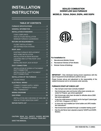
TERMS AND DEFINITIONSGeneral - This section of the manual provides a brief description of the elevator equipment to acquaint you withthe various components and the names by which they are identified. Figure 1 illustrates an elevator assembly.Bucket Elevator - The elevator assembly (Fig. 1) is the main assembly in the elevating system. It consists of thehead (1), boot (14), casing (11), service door (12), and belt/chain and buckets.Head - The head (Item 1, Fig. 1) is the topmost component in the elevator leg. It consists of a steel housingwhich supports the drive pulley/sprocket, discharge, motor and drive reducer.Boot - The boot (Item 14, Fig. 1) is the bottom component of the elevator. It receives the material to be elevatedand contains the lower belt pulley or sprocket. The take-up is normally located on the boot and is used for belttracking and belt or chain tensioning.Casing - Casing (Item 11, Fig.1) is manufactured in sections. It forms the structure for supporting the head,service platforms, ladder & cage, etc., while also providing a dust-tite and waterproof enclosure for the elevatorbelt or chain and buckets. Casing may be of single or dual design. The service door is a casing section withremovable panels to allow access for servicing the belt/chain and buckets.Discharge Transition - A transition is used to adapt a square outlet to round spouting or a distributor.Elevator Drive - Most Silver-Sweet elevator heads are electric motor-driven through shaft-mounted reducers(Item 4, Fig. 1). Large units use a motor-gear drive unit. Additional information may be found in a manual whichis supplied with each speed reducer.Service Platform for Head - (Item 9, Fig. 1) A work area for performing routine inspection and maintenance onthe elevator head, head drive and motor.Service Platform for Distributor - A work area for connecting spouting to the distributor and for performinginspection and maintenance of the distributor.Intermediate Platform - A rest area platform is available to comply with OSHA requirements for offsets of theladder every 30’ in commercial facilities.Ladder - Ladders provide access to the service platforms. Brackets are provided to install the ladders to theelevator casing frames in 5’ or 10’ increments.Safety Cage - The Sweet safety cage is of tubular construction and provides a surrounding structure around theladder.A Safety Climbing Device - A safety belt which is attached to a high tensile cable by means of a sliding, stainlesssteel clamp. This device meets OSHA requirements for ladder climbing safety and eliminates the need for safetycage, intermediate platforms and offset ladders.Guy Bracket - Clamp around the elevator casing for the attachment of guy cables. A single bracket assemblyprovides attachment points for four cables - one at each corner of the elevator casing.Hoist Assembly - An option that provides an extended arm, which pivots to aid in raising or loweringheavy head components from elevator during maintenance.Elevator Belts and Buckets - Material is carried from the boot to the head in elevator buckets, which are boltedto the belt. (See Fig. 1) A chain may be used instead of the belt.Sweetheart Elevator Buckets - Designed with proportioned body contour and high bucket ends which minimizespilling. “Wraparound ends” add extra strength for digging material and at both ends of the bucket body.Belting/Chain - This is the component that carries the filled buckets from the boot to the head. The standardbelting provides strong bolt holding ability and stretch resistance. It is resistant to oil and abrasives and has acover compound which resists static charges.Vent In Head - Provides an exhaust for air which may enter the elevator through the spouting. Head vents arestandard and installed at the factory. Elevators can have an inspection door in lieu of head vent upon request.4
Figure 1 - Typical Elevator Assembly and 11.12.13.14.15.16.17.18.19.20.21.HEADHEAD PULLEYBUCKETSPEED REDUCERV-BELTSMOTORELEVATOR BELTTORQUE ARMSERVICE PLATFORMCASING FLANGECASINGSERVICE DOORHOPPER (up side, top location)BOOTBOOT PULLEYHOPPER(down side,bottom location)PIT LEVELDRIVE COVERBAFFLE PLATE ADJUSTMENTCLEAN-OUT DOORSWORK OR GRADE LEVEL21151413201716Service Door Assembly5
Explosion Reli
installation, this manual is designed for you. The instructions and drawings give a step-by-step method of recommended installation procedures. Methods will vary among millwrights, but if you are not sure which is best, we suggest that you follow instructions in the manual. In addition to installation instructions, you will also find operating, maintenance and trouble shooting guides, as well .