Transcription
INSTALLATION INSTRUCTIONSMulti-Position Cased CoilsFor Cooling OnlyFEATURING R-410A OR R-22 REFRIGERANTRECOGNIZE THIS SYMBOL AS AN INDICATION OF IMPORTANT SAFETY INFORMATIONWARNINGThese instructions are intended as an aid to qualifiedlicensed service personnel for proper installation, adjustment and operation of this unit. Read these instructionsthoroughly before attempting installation or operation.Failure to follow these instructions may result in improperinstallation, adjustment, service or maintenance andpossibly resulting in fire, electrical shock, propertydamage, personal injury or death.DO NOT DESTROY THIS MANUALPlease read carefully and keep in a safe place for future reference by a serviceman.
TABLE OF CONTENTS1.0 SAFETY.32.0 GENERAL.42.1 CODES & REGULATIONS.42.2 INSPECTION UPON UNIT ARRIVAL. 42.3 CLEARANCES.42.4 UNIT DIMENSION AND COMPONENT LOCATION.53.0 INSTALLATION INSTRUCTIONS.63.1 REPLACEMENT PARTS.63.2 PRE-INSTALLATION INSTRUCTIONS.63.3 INSTALLATION AND TRAP CONNECTION.64.0 DRAIN APPLICATION.74.1 CONDENSATE DRAIN PIPING.74.2 PLASTIC DRAIN PAN INSTALLATION.75.0 REFRIGERANT CONNECTIONS.95.1 FLOWRATOR PISTON CHANGE.9LIST OF FIGURES AND TABLES.Fig.1 CASED DIMENSIONS AND COMPONENT LOCATION.5Fig.2 INSTALLATION AND DRAIN CONNECTIONS.6Fig.3 DRAIN LINE INSTALLATION.8Fig.4 DRAIN PIPE ROUTING.8Fig.5 FLOWRATOR PISTON CHANGE.9Table 1 FLOWRATOR PISTON SIZE CHART.10Table 2. AIRFLOW PERFORMANCE.112
1.0 SAFETYWhen you see the symbols below on labels or in manual, be alert to the potential orimmediate hazards of personal injury, property and/or product damage. It is theowner’s or installer’s responsibility to comply with all safety instructions and information accompanying these symbols.WARNINGThis is a safety alert symbol indicating a potential hazardous situation, whichcould result in personal injury, property and/or product damage or death.CAUTIONThis is a safety alert symbol indicating a potential hazardous situation, whichcould result in moderate personal injury, and/or property and productdamage.WARNINGDisconnect all power to the unit before starting any service and maintenance.Failure to do so could cause severe electrical shock resulting in personalinjury or death.WARNINGInstallation or servicing of this unit can be hazardous due to parts, components and system pressure. Qualified and proper trained service personnelshould perform installation and repair. Failure to do so could cause severeelectrical shock resulting in personal injure or death.WARNINGThese coils are not approved for oil furnace applications3
2.0 GENERALThe unit can be positioned for bottom return air in the upflow position, left and rightreturn in the horizontal position, top return in downflow position.2.1 CODES & REGULATIONSThis product is designed and manufactured to comply with national codes.Installation in accordance with such codes and/or prevailing local codes/regulationsis the responsibility of the installer. The manufacturer assumes no responsibility forequipment installed in violation of any codes or regulations.The United States Environmental Protection Agency(EPA) has issued variousregulations regarding the introduction and disposal of refrigerants. Failure to followthese regulations may harm the environment and can lead to the imposition ofsubstantial fines. Should you have any questions please contact the local office of theEPA.2.2 INSPECTION UPON UNIT ARRIVALAs soon as unit is received, it should be inspected and noted for possible shippingdamage during transportation. It is carrier’s responsibility to cover the cost of shippingdamage. Manufacturer or distributor will not accept a claim from contractors for anytransportation damage.2.3 CLEARANCESFollowing clearances should be provided during installationa.Maintenance and service access, including coil cleaning and coil assemblyremovalb.Refrigerant piping and connectionsc.Condensate drain line4
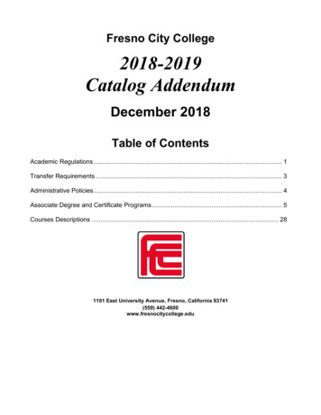
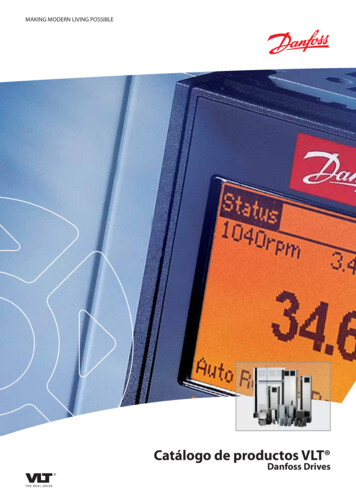
2.4 UNIT DIMENSION AND COMPONENT LOCATIONA19''VAPOR LINE CONNECTIONCOPPER (SWEAT)COIL ACCESSPANELLIQUID LINE CONNECTIONCOPPER (SWEAT)HHORIZONTAL DRAINCONNECTIONAUXILIARY DRAIN CONNECTION3/4'' NPT FEMALE PIPE THREAD21''WPRIMARY DRAIN CONNETION3/4'' NPT FEMALE PIPE THREADW120''Fig.1 CASED DIMENSIONS AND COMPONENT LOCATIONDIMENSIONAL DATADimensions inch [mm]UNITWEIGHT/SHIPPINGWEIGHT (LBS.[kg])MODEL SIZEUNIT HEIGHT"H"IN. [mm]UNIT WIDTH"W" IN.[mm]SUPPLY DUCT"A" IN.[mm]"W1" -1/2"[597]87/92[39.4]/[41.8]5
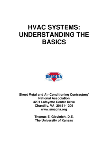
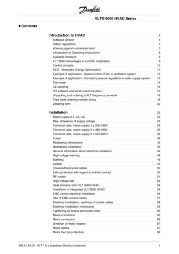
3.0 INSTALLATION INSTRUCTIONS3.1 PARTSContact your distributor for authorized replacement parts.3.2 PRE-INSTALLATION INSTRUCTIONSCarefully read all instructions for installation prior to installing product. Make sureeach step or procedure is understood and any special considerations are taken intoaccount before starting installation. Assemble all tools, hardware and suppliesneeded to complete the installation. Some items may need to be purchased locally.Make sure everything needed to install the product is on hand before starting.3.3 INSTALLATION AND TRAP CONNECTIONSee Fig .2 for coil installation and drain connection for vertical and horizontalapplications.Upflow DischargeDownflow Discharge FurnaceAlternate DrainFurnacePrimary DrainPrimary DrainAlternate DrainUpflow DrainDownflow DrainConnectionConnectionVertical Drain Conditions(All other drain connections should be plugged) Right HandDischargeFurnaceTrapped Left HandDischargeFurnaceTrappedHorizontal Drain Conditions(All other drain connections should be plugged)Fig.2 INSTALLATION AND DRAIN CONNECTIONS6
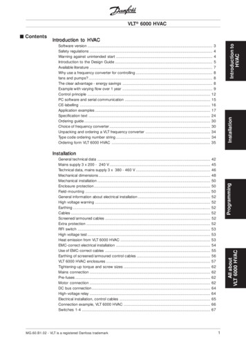
4.0 DRAIN APPLICATION4.1 CONDENSATE DRAIN PIPINGConsult local codes for special requirements.To provide extra protection from water damage, install an additional drain pan,provided by installer under the entire unit with a separate drain line. Manufacturer willnot be responsible for any damages due to the failure to follow these requirements.4.2 PLASTIC DRAIN PAN INSTALLATIONWARNINGDo not use the coil pan shipped with the unit on OIL furnaces or any application where the temperature of the drain pan may exceed 275oF. A fieldfabricated metal drain pan can also be used for these type of applications.Fallure to follow this warning may result in property damage and/orpersonal injury.The coil drain pan has a primary and an optional secondary drain with 3/4” NPTfemale connections; use either PVC or metal pipe and hand tighten to a torque ofapproximately 37 in-lbs. to prevent damage to the drain pan connection. An insertiondepth between .355 to .485 inches (3-5 turns) should be expected at this torquesetting.Use male 3/4” NPT threaded fitting for outside connection and make sure the drainholes are not blocked.Insulation may be needed for drain line to prevent sweating.Drain pan has two drain connections on each side to provide flexibility of connectionand drainage. Make sure pan has proper pitch and plugged if second connection isnot used.If the secondary drain line is required, run the line separately from the primary drainand end it where it can be easily seen.NOTE: Water coming from this line means the coil primary drain is plugged andneeds clearing.Install a trap in the drain line below the bottom of the drain pan. If using a copper drainline, solder a short piece of pipe to the connector before installing a drain fitting. DONOT over torque the 3/4” copper connector to the plastic drain connection. Use a wetrag or heatsink material on the short piece to protect plastic drain pan, complete thedrain line installation (Fig.3). Use (Fig.4) as a template for typical drain pipe routing.This figure shows how to avoid interference with vent piping.7
CONDENSATE DRAIN TRAP3"DO NOT OPERATE UNIT WITHOUTCONDENSATE DRAIN TRAP.3"UnitDO NOT OVERTIGHTEN DRAIN FITTINGUNIT MUST BE SLIGHTLY INCLINEDTOWARD DRAIN CONNECTIONTO APPROVED DRAINFig.3 DRAIN LINE INSTALLATIONsecondarysecondaryprimaryprimaryFig.4 DRAIN PIPE ROUTING8
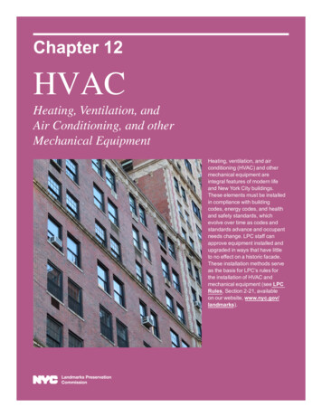
5.0 REFRIGERANT CONNECTIONSTo prevent refrigerant leak, use proper tools to ensure clean, burr-free cut.Use brazing shield when welding close to the cabinet surface and wet rag to protectrubber grommet.Brazing alloy should be at least 5% silver content.5.1 FLOWRATOR PISTON CHANGEIn most applications, there is no need to change the piston (orifice). However, insome mix-matched applications, change of piston size is required. If the applicationneeds to change the piston, change the piston in the distributor of indoor coil beforeinstalling the coil. See Table 1 for orifice size.To change the piston, use following steps:1.Remove cover panel.2.Use Two wrenches.Loosen one turn to release pressure. (High pressure gas)3.After releasing pressure.Loosen and carefully pull two fittings to expose piston.4.Remove and replace piston shown in Fig.5.5.Carefully reassemble assembly. (Hand tighten)Be sure to use teflon tape on thread for a complete seal.6.Hand tighten and make sure assembly is properly connected and then torqueto 10-30 ft/lb.NOTE: Be careful not to bend tubingLIQUID LINEPISTONNUT(TORQUE:11 2 lbf.ft)Fig.5 FLOWRATOR PISTON CHANGE9
Table 1 FLOWRATOR PISTON SIZE CHARTCondensing UnitA-CoilIf Piston ReplaceRequiredOptional ReplacePiston/TXV AM4CXC035BB1CAAAM4CXC035BC1CAAACondensing 049BC1CAAAM4CXC061BD1CAAANONOA-CoilIf Piston ReplaceRequiredOptional ReplacePiston/TXV C028BA1CAAA MAYTXVACHP3642AAM4CXC030BB1CAAA A AC4042A1000AAM4CXC049BC1CAAA C1CAAA MAYTXVACHP4848AAM4CXC061BD1CAAA AM4CXC061BD1CAAAMAYTXVACHP6060AAC09814C088
PRESSURE DROP CHARACTERISTICS FOR COOLING AND HEAT PUMP COILSPRESSURE DROP (INCHES OF 1
Base Limited WarrantySingle Phase R-410A Outdoor Units, Single Phase R-22 Outdoor Units, Air Handlers,Subject to the terms and conditions of this limited warranty, Ingersoll Rand (“Company’) extends a limited warranty against manufacturing defects for the product(s)Table 1 attached hereto (“Products’) that are installed in a residential/multi-family application (personal, family or household purposes) under normal use andmaintenance in the United States and Canada. All repairs of Product partscovered under this limited warranty must be made with authorized service parts and by a licensed HVAC service provider. Additionally, commercial applications are treateddifferently under this limited warranty as stated in Table 1 attached hereto. For purposes of this limited warranty, “commercial applications” shall mean any applicationother than for personal, family, or household use.TERM: The limited warranty period for Products is as stated in Table 1 attached hereto. If the Purchaser properly registers the Products, the limited warranty periodshall be extended as stated in Table 1 attached hereto. Regardless of registration, the Commencement Date for a limited warranty period shall be the date that the original’s invoice. If the installation and start-up date cannotWhere a Product is installed in a newly constructed home, the Commencement Date is the date the Purchaser purchased the residence from the builder. Proof of ProductThe installation of Product replacement parts under this limited warranty shall not extend the original warranty period. The warranty period for any Product partreplaced under this limited warranty is the applicable warranty period remaining under the original Product warranty.WHO IS COVERED: This limited warranty is provided only to the original owner and his or her spouse (“Purchaser’) of the residence where the Products are originallythe right to request any and all proof of Product purchase or installation and/or closing date of the residence.WHAT COMPANY WILL DO: Company may request proof of Product purchase and/or installation in order to provide Product parts under this limited warranty. AsCompany’s only responsibility and Purchaser’s only remedy under this limited warranty, Company will furnish a replacement part to the licensed HVAC service provider,without charge for the part only, to replace any Product part that fails due to a manufacturing defect under normal use and maintenance. The Purchaser must pay for anyand all shipping and handling charges and other costs of warranty service for the replacement part. If a Product part is not available, Company will, at its option, providea free suitable substitute part or provide a credit in the amount of the then factory selling price for a new suitable substitute part to be used by the Purchaser towards theretail purchase price of a new Company product. Any new Product purchase shall be at Purchaser’s sole cost and expense including, but not limited to, all shipping,removal, and installation costs and expenses.REGISTRATION REQUIREMENTS: All Products must be properly registered online by the Purchaser within sixty (60) days after the Commencement Date to receivethe registered limited warranty terms. To register online, go to:http://www.ameristarac.comand click “Begin Online Registration.” If a Purchaser does not register within this stated time period, the base limited warranty terms shall apply.ELIGIBILITY REQUIREMENTS: The following items are required in order for the Products to be covered under this limited warranty: The Products must be in the same location where they were originally installed. The Products must be properly installed, operated, and maintained by a licensed HVwarranty. Company may request written documentation showing the proper preventative maintenance. All Product parts replaced by Company under this limited warranty must be given to the servicing provider for return to Company. Air handlers, air conditioners, heat pumps, cased or uncased coils, stand-alone furnaces, and packaged units must be part of an Air Conditioning, Heating, andrepresentative.EXCLUSIONS: The following are not covered by this limited warranty: Labor costs including, but not limited to, costs for diagnostic calls or the removal and reinstallation of Products and/or Product parts. Shipping and freight expenses required to ship Product replacement parts. Failures, defects, or damage (including, but not limited to, any loss of data or property) caused by (1) any third party product, service, or system connected or usedwater, storms, lightning, or earthquakes; or any theft or riots; or (7) a corrosive atmosphere or contact with corrosive materials such as, but not limited to, chlorine, Products purchased direct including, but not limited to, Internet or auction purchases and purchases made on an uninstalled basis. factory installed driers, and Product accessories. Increased utility usage costs.REFRIGERANT POLICY: Beginning on January 1, 2010, R-22 refrigerant will no longer be used as a manufacturer-installed refrigerant as required by federal regulation. Any and all expenses or costs associated with replacing Product parts that are not R-410A compatible will not be covered by the terms and conditions of this limitedrefrigerant or any non-approved refrigerant system additives including, but not limited to, dyes, will void this limited warranty.ADDITIONAL TERMS:THIS LIMITED WARRANTY AND LIABILITY SET FORTH HEREIN ARE IN LIEU OF ALL OTHER WARRANTIES AND LIABILITIES, WHETHER IN CONTRACTOR IN NEGLIGENCE, EXPRESS OR IMPLIED, IN LAW OR IN FACT. THE IMPLIED WARRANTIES OF MERCHANTABILITY AND FITNESS FOR A PARTICULARPURPOSE ARE LIMITED TO THE DURATION OF THE APPLICABLE PRODUCT WARRANTY. COMPANY DOES NOT AUTHORIZE ANY PERSON TO CREATE FORIT ANY OBLIGATION OR LIABILITY IN CONNECTION WITH THE PRODUCTS.NOTWITHSTANDING ANYTHING IN THIS LIMITED WARRANTY TO THE CONTRARY, COMPANY SHALL NOT BE LIABLE FOR ANY INCIDENTAL, CONSEQUENTIAL, INDIRECT, SPECIAL AND/OR PUNITIVE DAMAGES, WHETHER BASED ON CONTRACT, WARRANTY, TORT (INCLUDING, BUT NOT LIMITED TO,STRICT LIABILITY OR NEGLIGENCE), PATENT INFRINGEMENT, OR OTHERWISE, EVEN IF ADVISED OF THE POSSIBILITY OF SUCH DAMAGES. COMPANY’SMAXIMUM LIABILITY HEREUNDER IS LIMITED TO THE ORIGINAL PURCHASE PRICE OF THE PRODUCTS.No action arising out of any claimed breach of this limited warranty may be brought by a Purchaser more than one (1) year after the cause of action has arisen. If this Product is considered a consumerproduct, please be advised that some local laws do not allow limitations on incidental or consequential damages, how long a warranty lasts based on registration, or how. If you have anylong an implied warranty lasts, so that the above limitations may not fully applyquestions regarding this limited warranty, please contact your original installation dealer, or any participating dealer, should your original installation dealer no longer beavailable.GW-659-2413
TABLE 1: Warranty Time PeriodsCOVERAGE TERMS FOR RESIDENTIAL APPLICATIONS: Pursuant to the Ingersoll Rand (“Company”) limited warranty terms and conditions, the following Products are covered for the base time periods as stated below(“Base Limited Warranty Period’). If registered, the Base Limited Warranty Periods for certain Products will beextended as stated below (“Registered Limited Warranty Period”).FURNACES:M801P, M951PRegistered Limited Warranty Period: Parts – ten (10) years, Heat Exchanger: twenty (20) years.AIR HANDLERS:M4AH3, M4AH4Registered Limited Warranty Period: Indoor Coil and Parts – ten (10) years.ELECTRIC HEATERS, installed in M4A3/4 AIR HANDLERS:MAYHTR1ARegistered Limited Warranty Period: Parts – ten (10) years.SINGLE PHASE R410 OUTDOOR UNITS:M4AC3, M4HP3, M4AC4, M4HP4Registered Limited Warranty Period: Compressor, Outdoor Coil, Parts – ten (10) years.SINGLE PHASE R22 OUTDOOR UNITS:M2AC3, M2HP3Base Limited Warranty Period: Compressor, Outdoor Coil, Parts - one (1) year.CASED COILS:M4CXCRegistered Limited Warranty Period: Coil and Parts – ten (10) years.PACKAGED UNITS:M4PH3, M4PG3Registered Limited Warranty Period: Compressor, Coil, Parts – ten (10) years, Heat Exchanger – ten (10) years.SPECIFIC TERMS FOR COMMERCIAL APPLICATIONSBase Limited Warranty Period Applies 2013 Ingersoll RandGW-659-2413
2020001B2533 V1.1
�。(20130605)V1.1版1.Table 1更改型号。(20130624)
INSTALLATION INSTRUCTIONS WARNING These instructions are intended as an aid to qualified licensed service personnel for proper installation, adjust- . 4.2 PLASTIC DRAIN PAN INSTALLATION WARNING Do not use the coil pan shipped with the unit on OIL furnaces or any appli-cation where the temperature of the drain pan may exceed 275oF. A field