Transcription
LONWORKS INTERFACE MODULETABLEOFCONTENTSOpenNet Interface Modules . . . . . . . . . . . . . . . . . . . . . . . . . . . . . . . . . . . . . . . . . . . 1LONWORKS Interface Module Features . . . . . . . . . . . . . . . . . . . . . . . . . . . . . . . . . . . . 1About LON . . . . . . . . . . . . . . . . . . . . . . . . . . . . . . . . . . . . . . . . . . . . . . . . . . . . . . . 1LONWORKS Network Components . . . . . . . . . . . . . . . . . . . . . . . . . . . . . . . . . . . . . . . . 2LONWORKS Network System Setup . . . . . . . . . . . . . . . . . . . . . . . . . . . . . . . . . . . . . . . 3LONWORKS Interface Module Parts Description . . . . . . . . . . . . . . . . . . . . . . . . . . . . . . 4LONWORKS Interface Module Specifications . . . . . . . . . . . . . . . . . . . . . . . . . . . . . . . . 5Wiring LONWORKS Interface Module . . . . . . . . . . . . . . . . . . . . . . . . . . . . . . . . . . . . . . 6Terminator . . . . . . . . . . . . . . . . . . . . . . . . . . . . . . . . . . . . . . . . . . . . . . . . . . . . . . . 7Link Registers for LONWORKS Network Communication . . . . . . . . . . . . . . . . . . . . . . . . 8Transmission Time . . . . . . . . . . . . . . . . . . . . . . . . . . . . . . . . . . . . . . . . . . . . . . . . . 9Function Area Setting for LONWORKS Node . . . . . . . . . . . . . . . . . . . . . . . . . . . . . . . . 10Programming Transmit/Receive Data Using WindLDR . . . . . . . . . . . . . . . . . . . . . . . . 11Starting Operation . . . . . . . . . . . . . . . . . . . . . . . . . . . . . . . . . . . . . . . . . . . . . . . . . 12Network Management . . . . . . . . . . . . . . . . . . . . . . . . . . . . . . . . . . . . . . . . . . . . . . 12Precautions for Modifying Application Program . . . . . . . . . . . . . . . . . . . . . . . . . . . . . 13LONWORKS Interface Module Internal Structure . . . . . . . . . . . . . . . . . . . . . . . . . . . . . 14Data Exchange between LONWORKS Interface Module and CPU Module . . . . . . . . . . . 16Application Program Examples . . . . . . . . . . . . . . . . . . . . . . . . . . . . . . . . . . . . . . . . 18Initialization . . . . . . . . . . . . . . . . . . . . . . . . . . . . . . . . . . . . . . . . . . . . . . . . . . . 18Writing Receive Data to Data Registers in the LONWORKS Interface Module . . . . . . 21Reading Transmit Data from Data Registers in the LONWORKS Interface Module . . . 22Defined Network Variables . . . . . . . . . . . . . . . . . . . . . . . . . . . . . . . . . . . . . . . . . . . 23LONWORKS Network Troubleshooting . . . . . . . . . . . . . . . . . . . . . . . . . . . . . . . . . . . . 828Index . . . . . . . . . . . . . . . . . . . . . . . . . . . . . . . . . . . . . . . . . . . . . . . . . . . . . . . . . . 29OPENNET CONTROLLER LONWORKS INTERFACE MODULE USER’S MANUALi
LONWORKS INTERFACE MODULEIntroductionThis manual describes LONWORKS interface module FC3A-SX5LS1 used with the OpenNet Controller to interface withthe LONWORKS network, and provides details on the LONWORKS system setup and the LONWORKS interface module specifications.For general information about safety precautions, installation, wiring, and dimensions, see the OpenNet Controller user’smanual EM333.OpenNet Interface ModulesThe OpenNet Controller can be linked to three major open networks; INTERBUS, DeviceNet , and LONWORKS . Forcommunication through these networks, OpenNet interface modules are available. Mounting the LONWORKS interfacemodule beside the OpenNet Controller CPU module makes up a node on a LONWORKS network. The node can communicate I/O data with other nodes in a distributed network.LONWORKS Interface Module FeaturesThe LONWORKS interface module conforms to the specifications of LONWORKS that is recognized worldwide as a de factoindustry standard open network, so the OpenNet Controller can be linked to the LONWORKS networks consisting of LONWORKS compliant products manufactured by many different vendors, such as I/O terminals, sensors, drives, operator interfaces, and barcode readers. The flexible, configurable, and interoperable features of the LONWORKS network make itpossible to build, expand, or modify production lines with reduced cost.The transmit/receive data quantity can be selected from 0 through 8 bytes (64 bits) in 1-byte increments. One LONWORKSinterface module enables the OpenNet Controller CPU module to transmit 64 bits and receive 64 bits at the maximum toand from the LONWORKS network.The network can be configured either in bus or free topology. The total transmission distance can be 1,400m in bus topology and 500m in free topology. The free topology makes it possible to configure a flexible network.About LONThe LON (Local Operating Network) technology is a network control system developed by Echelon, USA. The LONtechnology is an intelligent, distributed network for communication with various sensors and actuators at a maximum of32,385 nodes.LONWORKS is the open control standard for buildings, factories, houses, and transportation systems. Now, LONWORKSnetworks are widely used in major building automation (BA), process automation (PA), and many other industries in theworld.Communication between application programs installed in LonWorks compliant nodes is performed using the LonTalkprotocol based on the reference model of the Open System Interconnection (OSI) issued by the International StandardOrganization (ISO).OpenNet Controller and WindLDR are trademarks of IDEC CORPORATION.LON, LONWORKS, LonBuilder, Echelon, Neuron, LonTalk, and 3150 are registered trademarks of Echelon Corporation registered in the United States and other countries. LonMaker is a trademark of Echelon Corporation.DeviceNet is a trademark of Open DeviceNet Vendor Association, Inc. (ODVA).OPENNET CONTROLLER LONWORKS INTERFACE MODULE USER’S MANUAL1
LONWORKS INTERFACE MODULELONWORKS Network ComponentsPhysical Layer — TransceiverThe LONWORKS interface module incorporates an FTT-10A (Free Topology Twisted Pair Transceiver) for the physicallayer. The FTT-10A transceiver is a transformer-isolated type and has the following ateFTT-10A TransceiverTwisted pair cable78 kbpsTransmission DistanceTopology500m (maximum total wire length)400m (maximum node-to-node distance)Free1,150mBusNote: The transmission distance is the value when Level 4 AWG22 cables and proper terminators are used.LonTalk ProtocolThe LonTalk protocol has all seven layers in compliance with the reference model of the Open System Interconnection(OSI) issued by the International Standard Organization (ISO).Neuron ChipSome special LSI Neuron Chips that support the LonTalk protocol have firmware embedded in the built-in memory. TheNeuron Chip used in the LONWORKS interface module is Toshiba TMP3150B1AF, with firmware embedded in the external memory (flash memory). This Neuron Chip uses a 10MHz quartz clock oscillator. The Neuron Chip and peripheral circuit are powered through the CPU bus.Application ProgramThe application program for the LONWORKS interface module is in compliance with the application layer of the OSI reference model, and is described in Neuron C that is derived from ANSI C.Communication data is transferred through the registers located between the OpenNet Controller CPU bus and the NeuronChip external memory expansion bus. An application program including access to the registers is created and embedded inthe external memory (flash memory) along with firmware by IDEC before shipment. Users do not have to create andinstall application programs, although programmers familiar with Neuron C can also create or modify the application program using a special tool, such as LonBuilder Developer’s Kit. When a user creates or modifies the application program,the user must keep a backup file. For application program examples, see pages 18 through 22.Network VariablesThe LonTalk protocol allocates communication data to network variables (NV) specifically designed to simplify the procedures for packet transmission. The variables are available in input network variables and output network variables. Thevalues of output network variables are transmitted to input network variables of the target node on the network. Details aredescribed on pages 9 and 23.Network ManagementWhen setting up a LONWORKS network system, the user has to install network configuration information shown below.Addressing:Binding:Configuration:Determines each node addressDetermines target nodes to communicate withDetermines the type of message service, retry cycles, timeout period, etc.Use a network management tool from other manufacturers (such as LonMaker for Windows Integration Tool) to installnetwork configuration information. An external interface file (XIF extension) unique to each product series is needed toinstall the network configuration information. The external interface file for the LONWORKS interface module is availablefrom IDEC. The user must keep a backup file of the information used for network management.2OPENNET CONTROLLER LONWORKS INTERFACE MODULE USER’S MANUAL
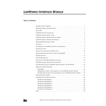
LONWORKS INTERFACE MODULELONWORKS Network System SetupVarious LONWORKS compliant devices, such as the LONWORKS interface module and IDEC SX5L communication I/Oterminals, can be connected to the LONWORKS network.The OpenNet Controller can be used as a node by adding the LONWORKS interface module to the right of the OpenNetController CPU module.A maximum of seven OpenNet interface modules and analog I/O modules can be mounted with one OpenNet ControllerCPU module.LONWORKS NetworkPOWERPOWRUNERRI/OSERRUNERRORHSC OUTCOM ASERVICEREQUEST012345671011121314151617BRS485Z HSCOUT A B G 24V 0VIDEC SX5L Communication I/O TerminalLONidecIDECOpenNet ControllerCPU ModuleI/O ModuleLONWORKS Interface ModuleFC3A-SX5LS1IDEC SX5L Communication I/O TerminalOther LONWORKS Compliant DevicesOPENNET CONTROLLER LONWORKS INTERFACE MODULE USER’S MANUAL3
LONWORKS INTERFACE MODULELONWORKS Interface Module Parts DescriptionExpansion Connector(1) Module ID(5) Status LED(2) FG TerminalSERVICEREQUESTLON(3) Service Request Button(4) Network Interface ConnectorOpenNet Interface Module for LONWORKS NetworkModule NameLONWORKS Interface ModuleType No.FC3A-SX5LS1(1) Module IDFC3A-SX5LS1 indicates the LONWORKS interface module ID.(2) FG TerminalFrame ground terminal(3) Service Request ButtonPushbutton used for network management(4) Network Interface ConnectorFor connecting the LONWORKS communication cable(5) Status LEDIndicates operating statusIndicatorPOW (POWER)RUNERR(COM ERROR)I/O (I/O ERROR)SER (SERVICE)4StatusDescription—OFFModule power OFFGreenONModule power ONGreenONNormal operation—OFFNormal operationRedONCommunication error—OFFNormal operationRedYellowONAccess error to the CPU through I/O busONApplication program not configuredFlashNetwork management not configuredOPENNET CONTROLLER LONWORKS INTERFACE MODULE USER’S MANUAL
LONWORKS INTERFACE MODULELONWORKS Interface Module SpecificationsNormal Operating ConditionsOperating Ambient Temperature0 to 55 C (no freezing)Storage Temperature–25 to 70 C (no freezing)Operating HumidityLevel RH1 30 to 90% (no condensation)Pollution Degree2 (IEC 60664)Corrosion ImmunityFree from corrosive gasesAltitudeOperation:Transportation:Vibration Resistance10 to 57 Hz, amplitude 0.075 mm; 57 to 150 Hz, acceleration 9.8 m/sec2 (1G);10 sweep cycles each in 3 axes (total 80 minutes) (IEC1131)Shock Resistance147 m/sec2 (15G), 11 msec, 3 shocks each in 3 axes (IEC1131)0 to 2000m0 to 3000mPower Supply (supplied from the OpenNet Controller CPU module)Dielectric StrengthBetween power terminal on CPU module and FG: 500V AC, 1 minuteInsulation ResistanceBetween power terminal on CPU module and FG: 10 MΩ (500V DC megger)Current DrawApprox. 30 mAGroundingGround TerminalM3 semsGrounding Resistance100Ω maximumGrounding WireUL1015 AWG22, UL1007 AWG18WeightWeightApprox. 180gCommunication SpecificationsCommunication SystemLON systemTransceiverFTT-10A (Free Topology Twisted Pair Transceiver made by Echelon)Transmission Rate78 kbpsTransmission Distance(when using Level 4 AWG22 cables)Free topology:Bus topology:Maximum Nodes32,385 nodes in a networkNetwork Interface ConnectorIn the module:To the cable:Network Cable1-wire connection: 0.2 to 2.5 mm2, AWG24 to 142-wire connection: 0.2 to 1.5 mm2, AWG24 to 16Total 500m (400m maximum between nodes)1,150m (when using FTT-10A transceivers only)MSTB2.5/2-GF-5.08 (made by Phoenix Contact)FRONT-MSTB2.5/2-STF-5.08 (made by Phoenix Contact)OPENNET CONTROLLER LONWORKS INTERFACE MODULE USER’S MANUAL5
LONWORKS INTERFACE MODULEWiring LONWORKS Interface ModulePrecautions for Wiring Use a twisted-pair cable to connect the LONWORKS interface module to the network. Do not run the network cable inparallel with or near power lines, output lines, and motor lines. Keep the network cable away from noise sources. Power down the LONWORKS interface module before you start wiring. Make sure wiring is correct before powering upthe LONWORKS interface module. One or two cables can be connected to one terminal of the network interface connector. When connecting one cable, use AWG24 to AWG14 cables (core cross-section 0.2to 2.5 mm2). When connecting two cables to one terminal, use the same cables ofAWG24 to AWG16 (0.2 to 1.5 mm2). Do not use cables of different diameters. Stripthe cable insulation as shown at right.7 mm Tighten the mounting screws of the network interface connector to a recommended torque of 0.3 to 0.5 N·m. Tighten the terminal screws of the network interface connector to a recommended torque of 0.5 to 0.6 N·m. To prevent electrical shocks or communication error due to noises, connect the FG terminal to a proper ground using agrounding wire of UL1015 AWG22 or UL1007 AWG18 (grounding resistance 100Ω maximum). Do not connect thegrounding wire in common with the grounding wire of motor equipment.Ferrules, Crimping Tool, and Screwdriver for Phoenix Terminal BlocksThe screw terminal block of the network interface connector can be wired with or without using ferrules on the end of thecable. Applicable ferrules for the terminal block and crimping tool for the ferrules are listed below. Use a screwdriver totighten the screw terminals on the LONWORKS interface module. Ferrules, crimping tool, and screwdriver are made by andavailable from Phoenix Contact.Type numbers of Phoenix Contact ferrules, crimping tool, and screwdriver are listed below. When ordering these productsfrom Phoenix Contact, specify the Order No. and quantity listed below. Ferrule Order No.Applicable Wire Sizemm2AWGFor 1-wire connectionPhoenix TypeOrder No.For 2-wire connectionPhoenix TypeOrder No.0.2524AI 0,25-8 YE32 00 85 2——1000.520AI 0,5-8 WH32 00 01 4AI-TWIN 2 x 0,5-8 WH32 00 93 31000.7518AI 0,75-8 GY32 00 51 9AI-TWIN 2 x 0,75-8 GY32 00 80 71001.018AI 1-8 RD32 00 03 0AI-TWIN 2 x 1-8 RD32 00 81 01001.516AI 1,5-8 BK32 00 04 3AI-TWIN 2 x 1,5-8 BK32 00 82 31002.514AI 2,5-8 BU32 00 52 2—100For 1-wire ConnectionA8.0 mmFerruleDimensionAAI 0,25-8 YE4.5 mmAIAIAIAIAI0,5-8 WH0,75-8 GY1-8 RD1,5-8 BK2,5-8 BU6.0 mm—For 2-wire connectionB8.0 mmFerruleDimensionBAI-TWIN 2 x 0,5-8 WHAI-TWIN 2 x 0,75-8 GYAI-TWIN 2 x 1-8 RD7.0 mmAI-TWIN 2 x 1,5-8 BK8.0 mm Crimping Tool and Screwdriver Order No.Tool Name6Pcs./Pkt.Phoenix TypeOrder No.Pcs./Pkt.Crimping ToolCRIMPFOX UD 612 04 43 61ScrewdriverSZS 0,6 x 2,512 05 04 010OPENNET CONTROLLER LONWORKS INTERFACE MODULE USER’S MANUAL
LONWORKS INTERFACE MODULETerminatorTerminators must be connected to the LONWORKS network. When setting up a network, connect one or two terminatorsdepending on the topology. The terminator consists of one resistor and two capacitors as illustrated below:Terminator ConfigurationC1 RC2 NetworkBus TopologyConnect terminators to the both ends of the bus topology network.R105Ω, 1%, 1/8WC1 and C2100 µF, 50V (note the odeNodeFree TopologyConnect a terminator to any position on the free topology network.R52.3Ω, 1%, 1/8WC1 and C2100 µF, 50V (note the NNET CONTROLLER LONWORKS INTERFACE MODULE USER’S MANUAL7
LONWORKS INTERFACE MODULELink Registers for LONWORKS Network CommunicationLONWORKS network communication data is stored to link registers in the OpenNet Controller CPU module and the data iscommunicated through the LONWORKS interface module.Since seven functional modules, including a LONWORKS interface module, can be mounted with one OpenNet ControllerCPU module, link registers are allocated depending on the position where the LONWORKS interface module is mounted.Link Register Allocation NumbersAllocationNumberAreaFunctionL*00Data areaReceive dataStores received data from the networkReadL*01Data areaReceive dataStores received data from the networkReadL*02Data areaReceive dataStores received data from the networkReadL*03Data areaReceive dataStores received data from the networkReadL*04Data areaTransmit dataStores transmit data for the networkWriteL*05Data areaTransmit dataStores transmit data for the networkWriteL*06Data areaTransmit dataStores transmit data for the networkWriteL*07Data areaTransmit dataStores transmit data for the networkWriteL*12Status areaError dataStores various error codesReadL*13Status areaI/O countsStores the byte counts of transmit/receive dataReadL*24ID areaSoftware versionStores the user application software versionReadL*25ID areaExpansion module IDStores the user program module IDReadDescriptionR/WNote: A number 1 through 7 comes in place of * depending on the position where the functional module is mounted, suchas OpenNet interface module or analog I/O module. Consequently, operand numbers are automatically allocated to eachfunctional module in the order of increasing distance from the CPU module, starting with L100, L200, L300, through L700.Error Data (Status Area) L*12L*12b15 b14: unused b13b12b11b10-b0: unusedWhen an error occurs, the I/O or ERR LED on the LONWORKS interface module goes on, according to the error, and a corresponding bit in the link register goes on. The status LED goes off when the cause of the error is removed. The error databit remains on until the CPU is powered up again or reset.b15 (initialization error)This bit goes on when the CPU module fails to acknowledge the completion of initialization for communication with theLONWORKS interface module. When this bit goes on, the I/O LED also goes on.b13 (I/O error)This bit goes on when an error occurs during communication with the LONWORKS interface module through the CPU bus.When this bit goes on, the I/O LED also goes on.b12 (transaction timeout)This bit goes on when the CPU module fails to receive an acknowledge reply during communication through the LONWORKS network, with the acknowledge (ACKD) service enabled. When this bit goes on, the ERR LED also goes on. Thetransaction timeout is enabled only when the ACKD service is selected.b11 (transmission error)This bit goes on when a CRC error is detected while receiving incoming data from the LONWORKS network. When this bitgoes on, the ERR LED also goes on.I/O Counts (Status Area) L*13L*13 b15-b12: transmit bytesb11-b8: receive bytesb7-b0: unusedThis link register stores the transmit and receive byte counts selected in the Function Area Setting Open Bus inWindLDR .8OPENNET CONTROLLER LONWORKS INTERFACE MODULE USER’S MANUAL
LONWORKS INTERFACE MODULELink Registers and Network VariablesNetwork variables are allocated to data areas of the link registers as shown below.b15b14b13b12b11b10b9b8b7b6b5b4b3L*00nv i8[1]nv i8[0]L*01nv i8[3]nv i8[2]L*02nv i8[5]nv i8[4]L*03nv i8[7]nv i8[6]L*04nv o8[1]nv o8[0]L*05nv o8[3]nv o8[2]L*06nv o8[5]nv o8[4]L*07nv o8[7]nv o8[6]b2b1b0 ExampleNetwork variables nv i8[0] and nv i8[1] are allocated to link register data areas L100.00 through L100.15 as listed below.nv i8[1]nv i8[0]L100 b15 b14 b13 b12 b11 b10MSB100011b9b81LSB MSB10b7b61b50b40b30b21b1b01LSB1Transmission TimeThe transmission time depends on the network configuration, application program, and user program. It is recommendedthat you confirm the transmission time on the actual network system.Processing transmit and receive data to and from the LONWORKS network is described below: Processing Transmit DataThe data in link registers are updated each time the CPU module scans the user program. The LONWORKS interface module reads data from the link registers allocated to transmit data in the OpenNet Controller CPU module. When any changesare found in the comparison between the new and old read data, the interface module updates the transmit network variables of which the data has been changed, and the new data is transmitted to the network.The refresh cycle of reading from the link register to the interface module is approximately 15 msec. When the data in thelink register is changed within 15 msec, the preceding data is not transmitted to the interface module. Data communicationbetween the CPU module and the interface module through link registers is not in synchronism with the user programscanning.When the CPU is powered up, the transmit data in the link registers are cleared to 0. Consequently, 0 cannot be transmittedin the first cycle immediately after the CPU is powered up because the transmit network variables are not updated. Processing Receive DataWhen the interface module receives data from the network, corresponding receive network variables are updated, and theupdated data is stored to the receive data area of link registers in the CPU module.The refresh cycle of reading from the interface module to the link register is also approximately 15 msec, and is not in synchronism with the user program scanning. When the interface module receives subsequent data within 15 msec, the incoming data is stored in the buffer and is transmitted to link registers every 15 msec. The data in the link register is read eachtime the CPU module scans the user program.OPENNET CONTROLLER LONWORKS INTERFACE MODULE USER’S MANUAL9
LONWORKS INTERFACE MODULEFunction Area Setting for LONWORKS NodeThe quantity of transmit/receive data for LONWORKS network communication is specified using the Function Area Settingin WindLDR. The OpenNet Controller CPU module recognizes all functional modules, such as OpenNet interface modulesand analog I/O modules, automatically at power-up and exchanges data with LONWORKS nodes through the link registersallocated to each node.Since these settings relate to the user program, the user program must be downloaded to the OpenNet Controller afterchanging any of these settings.Programming WindLDR1. From the WindLDR menu bar, select Configure Function Area Settings. The Function Area Setting dialog boxappears.2. Select the Open Bus tab.Configure CommunicationMaster Module Check BoxCheck this box only whenthe remote I/O mastermodule is used.Quantity of Nodes ConnectedWhen using the remote I/O master module, specify the quantityof nodes from 1 through 32.Slave StationTransmit/ReceiveData Quantity (Bytes)When using OpenNet interface modules for DeviceNet,INTERBUS, or LONWORKS,specify the data bytes tocommunicate through eachOpenNet interface module.Transmit/Receive Bytes 0 to 8(default: 8 bytes)This value determines the dataquantity 0 through 8 bytes (64bits) to communicate with thenetwork.For the example on the nextpage, select 8 transmit bytes and4 receive bytes for Module 1.3. Select transmit and receive data bytes for module position 1 through 7 where the LONWORKS interface module ismounted.4. Click the OK button and download the user program to the OpenNet Controller.10OPENNET CONTROLLER LONWORKS INTERFACE MODULE USER’S MANUAL
LONWORKS INTERFACE MODULEProgramming Transmit/Receive Data Using WindLDRThe OpenNet interface module exchanges data between the open network and the link registers in the CPU module allocated to the OpenNet interface module, depending on the slot where the OpenNet interface module is mounted.To create a communication program for an OpenNet interface module, first determine the slot number where the OpenNetinterface module is mounted, and make a program to write data to link registers allocated to transmit data and to read datafrom link registers allocated to receive data.Example: When a LONWORKS interface module is mounted in the first slot of all functional modules Transmit DataMOV(W)I0S1 –65535D1 RL104REP4S1 RL100D1 RD0REP265535 L104 through L107When input I0 is on, constant 65535 (FFFFh) designated by source operand S1 is moved to four link registers L104 through L107 designated bydestination operand D1. All 64 bits (8 bytes) in link registers L104through L107 are turned on. Since link registers L104 through L107transmit data, the data is transmitted to the network. Receive DataMOV(W)I1L100·L101 D0·D1When input I1 is on, 32-bit (4-byte) data in two link registers L100 andL101 designated by source operand S1 is moved to data registers D0 andD1 designated by destination operand D1. Since link registers L100 andL101 receive data, communication data read to L100 and L101 is movedto data registers D0 and D1.OPENNET CONTROLLER LONWORKS INTERFACE MODULE USER’S MANUAL11
LONWORKS INTERFACE MODULEStarting OperationThe LONWORKS network requires installation of network configuration information into each node. When setting up theLONWORKS network for the first time, follow the procedures described below:1. Set up the OpenNet Controller CPU and LONWORKS interface modules, connect the LONWORKS interface module tothe LONWORKS network using LONWORKS cables, and power up the CPU module.2. Connect a network management tool to the network and install network configuration information to the LONWORKSinterface module. See Network Management described below.3. Download the user program to the CPU module.4. Start the CPU module to run, then the CPU module starts to communicate with other nodes on the LONWORKS network as specified in the network configuration information and user program.The delay until the communication starts after power-up depends on the size of the user program and the system setup.While the CPU is stopped, data exchange between the CPU and LONWORKS interface modules is halted, but communication with the LONWORKS network continues.Data exchange between the CPU and LONWORKS interface modules is asynchronous with the user program scanning inthe CPU module.Network ManagementWhen setting up a LONWORKS network system, the user has to install network configuration information into each node.Use a network management tool available from other manufacturers (such as LonMaker for Windows Integration Tool) toinstall network configuration information. An external interface file (XIF extension) unique to each product series isneeded to install the network configuration information. The external interface file for the LONWORKS interface module isavailable from IDEC. Find an XIF No. printed on the side of the LONWORKS interface module or on the shipping package.When requesting an external interface file, inform IDEC of the XIF No. that represents the external interface file versionnumber. Without a correct external interface file of the matching XIF No., network configuration information cannot beinstalled successfully.The network configuration information includes addressing, binding, and ermines each node addressDetermines target nodes to communicate withDetermines the type of message service, retry cycles, timeout period, etc.Caution When using the LONWORKS interface module, select the acknowledge (ACKD) service to enablethe message service for network variables and set the retry cycles to a value of 1 or more. If communication is performed using other than the ACKD service, the ERR LED on the interface module does not function properly. When installing the network configuration information without modifying the application program, an external interface file (XIF extension) containing information, such as the network variables of the LONWORKS interface module, is needed. Consult IDEC for the external interface file. The user must keep a backup file of the network configuration information used for network management.12OPENNET CONTROLLER LONWORKS INTERFACE MODULE USER’S MANUAL
LONWORKS INTERFACE MODULEPrecautions for Modifying Application ProgramThe LONWORKS interface module is shipped with a standard application program installed. Users with expertise in programming can also modify or create application programs using a special programming tool, such as LonBuilder Developer’s Kit. The application program is written in Neuron C. Read this section before starting modifications.Define Neuron Chip I/O pinsAs shown in the sample program on page 19, define I/O pins IO.0 through IO.4 and IO.6 of the Neuron Chip. If these pinsare not defined correctly, the LONWORKS interface module may be damaged. For the description of I/O pins, see page 15.Include necessary codes in the application programWhen you modify or create an application program, make sure that the codes shown in italics in the application programexamples on pages 18 through 22 are included in the application program.Defined network variablesThe application program installed in the LONWORKS interface module defines network variables for transmit and receivedata listed on page 23. When you modify or create an application program, do not use these variable names, otherwise verification of the application program will be difficult.Precautions for writing and reading registersMake a program to write and
LONWORKS INTERFACE MODULE 2OPENNET CONTROLLER LONWORKS INTERFACE MODULE USER'S MANUAL LONWORKS Network Components Physical Layer — Transceiver The LONWORKS interface module incorporates an FTT-10A (Free Topology Twisted Pair Transceiver) for the physical layer. The FTT-10A transceiver is a transformer-isolated type and has the following specifications: Note: The transmission distance is .