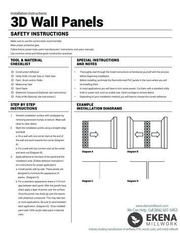
Transcription
Installation Instructions and Use & Care GuideRESIDENTIAL DIRECT VENT GAS WATER HEATERS SHIPPED SET FOR NATURAL GAS AND CONVERTIBLETO L.P. (PROPANE) GAS. ALL PARTS INCLUDED. FOR POTABLE WATER HEATING ONLY. NOT SUITABLEFOR SPACE HEATING. FOR DIRECT VENT INSTALLATION IN A MANUFACTUREDHOME (MOBILE HOME) ONLY. FOR USE ONLY WITH VENTING SYSTEMS SUPPLIEDWITH THE WATER HEATER, WHETHER A NEWINSTALLATION OR A REPLACEMENT INSTALLATION.For Your SafetyAN ODORANT IS ADDED TO THE GAS USEDBY THIS WATER HEATER. Safety Instructions Installation Operation Care and Maintenance Troubleshooting Parts ListINSTALLER: AFFIX THESE INSTRUCTIONS TO OR ADJACENT TOTHE WATER HEATER.WARNING: If the information in theseinstructions is not followed exactly, a fireor explosion may result causing propertydamage, personal injury or death.— Do not store or use gasoline or otherflammable vapors and liquids in thevicinity of this or any other appliance.— WHAT TO DO IF YOU SMELL GASOWNER: RETAIN THESE INSTRUCTIONS AND WARRANTY FORFUTURE REFERENCE. RETAIN THE ORIGINAL RECEIPTAS PROOF OF PURCHASE.WARNING: Gas leaks can not always be detected bysmell.Gas suppliers recommend that you use a gas detectorapproved by UL or CSA. Do not try to light any appliance. Do not touch any electrical switch;do not use any phone in yourbuilding. Immediately call your gas supplierfrom a neighbor’s phone. Followthe gas supplier’s instructions. If you cannot reach your gassupplier, call the fire department.For more information, contact your gas supplier.If a gas leak is detected, follow the “WHAT TO DO IF YOUSMELL GAS” instructions.LOW LEADCONTENT— Installation and service must beperformed by a qualified installer,service agency or the gas supplier.ALL TECHNICAL AND WARRANTY QUESTIONS: SHOULD BE DIRECTED TO THE LOCAL DEALER FROM WHOM THE WATER HEATER WAS PURCHASED.IF YOU ARE UNSUCCESSFUL, CONTACT THE COMPANY LISTED ON THE RATING PLATE ON THE WATER HEATER.PRINTED IN THE U.S.A. 08161PART NO. 100274627/2000534169 REV A
SAFE INSTALLATION, USE AND SERVICEThis is the safety alert symbol. It is used to alert you to potential personal injury hazards.Obey all safety messages that follow this symbol to avoid possible injury or death.DANGER indicates an imminently hazardous situation which, if not avoided, willresult in death or injury.WARNING indicates a potentially hazardous situation which, if not avoided, could resultin death or injury.CAUTION indicates a potentially hazardous situation which, if not avoided, could resultin minor or moderate injury.CAUTION used without the safety alert symbol indicates a potentially hazardoussituation which, if not avoided, could result in property damage.NOTICE Indicates information considering important but not hazard related.Your safety and the safety of others is extremely important in the installation, use and servicing of this water heater.Many safety-related messages and instructions have been provided in this manual and on your own water heater to warn you and others ofa potential injury hazard. Read and obey all safety messages and instructions throughout this manual. It is very important that the meaningof each safety message is understood by you and others who install, use or service this water heater.All safety messages will generally tell you about the type of hazard, what can happen if you do not follow the safety message andhow to avoid the risk of injury.This product is certified to comply with a maximum weighted average of 0.25% lead content as required in some areas.IMPORTANT DEFINITIONS Qualified Technician: A qualified technician must have ability equivalent to a licensed tradesman in the fields of plumbing, air supply,venting, and gas supply, including a thorough understanding of the requirements of the National Fuel Gas Code as it relates to theinstallation of gas fired water heaters. The qualified technician must also be familiar with the design features and use of flammable vaporignition resistant water heaters, and have a thorough understanding of this instruction manual.Service Agency: A service agency also must have ability equivalent to a licensed tradesman in the fields of plumbing, air supply, ventingand gas supply, including a thorough understanding of the requirements of the National Fuel Gas Code as it relates to the installation ofgas fired water heaters. The service agency must also have a thorough understanding of this instruction manual, and be able to performrepairs strictly in accordance with the service guidelines provided by the manufacturer.Gas Supplier: The natural gas or propane utility or service who supplies gas for utilization by the gas burning appliances within thisapplication. The gas supplier typically has responsibility for the inspection and code approval of gas piping up to and including the naturalgas meter or propane storage tank of a building. Many gas suppliers also offer service and inspection of appliances within the building.WARNINGFIRE AND EXPLOSION HAZARDCan result in serious injury or deathFLAMMABLESDo not store or use gasoline or otherflammable vapors and liquids in the vicinity of thisor any other appliance. Storage of or use ofgasoline or other flammable vapors or liquids in thevicinity of this or any other appliance can result inserious injury or death.Flammable VaporsRead and follow water heater warnings and instructions.2
Water temperature over 125 F(52 C) can cause servere burnsinstantly resulting in severe injury ordeath.Children, the elderly, and thephysically or mentally disabled are athighest risk for scald injury.Feel water before bathing Read instruction manual for safetemperature setting.Breathing Hazard - Carbon Monoxide GasInstall vent system in accordance withcodes.Do not operate water heater if flooddamagedHigh altitude orifice must be installed foroperation above 5,400 feet (1,645.9 m)Fire or Explosion HazardDo not store or use gasoline or other flammable vapors andliquids in the vicinity of this or any other appliance.Do not store or use gasoline or other flammable vapors andliquids in the vicinity of the water heater air intake.Avoid all ignition sources if you smell Natural or LP gas.Do not expose water heater control to excessive gaspressure.Use only gas shown on rating plate unless the water heaterhas been properly converted.Follow conversion instructions listed in manual whenconverting to opposite gas.Maintain required clearances to combustibles.Keep ignition sources away from faucets after extendedperiod of non-use.Do not operate if soot is present.Do not obstruct water heater air intakeDo not place chemical vapor emittingproducts near water heater.Gas and carbon monoxide detectorsare available.Breathing carbon monoxide can cause brain damage or death.Always read and understand instruction manual.Read instruction manual beforeinstalling, using or servicingwater heater.DANGERDo not use this water heater with any gas other than theone listed on the rating plate unless the water heater hasbeen properly converted.Refer to the “Gas Conversion” section of this manual toconvert from one gas to another. Failure to use thecorrect gas can cause problems which can result indeath, serious bodily injury or property damage. If youhave any questions or doubts, consult your gas supplieror gas utility company. Water heaters using bottledpropane or liquefied petroleum gas (LPG) are differentfrom natural gas models. A natural gas water heater willnot function safely on bottled propane or liquefiedpetroleum gas (LPG) and a propane gas water heater willnot function safely on natural gas.3
TABLE OF CONTENTSSAFE INSTALLATION, USE AND SERVICE.2GENERAL SAFETY.2-3TABLE OF CONTENTS.4INTRODUCTION .4Preparing for the New Installation .4TYPICAL INSTALLATION.5-6LOCATING THE NEW WATER HEATER .7Facts to Consider About Location .7-8Insulation Blankets .9INSTALLING THE NEW WATER HEATER .9-20Water Heater Installation .9-10Securing Water Heater to Floor and Wall .10Roof Jack Installation .11-12Manufactured Home installed Over Basement orCrawlspace-Air Intake Through an Outside wall .12-13Cutting Opening Through an Outside Wall andCollar Installation .13Cementing PVC, ABS or CPVC Pipe and Fittings .13-14Water Piping .14T & P Valve and Pipe Insulation .14-15Water Piping Pressure Test .15Temperature Pressure Relief Valve .15-16Filling the Water Heater .16Gas Requirements .17Gas Piping .17Gas Pressure/Gas Pressure Testing .17LP Gas Only .18Sediment Traps .18Installation Requirements for Massachusetts .20INSTALLATION CHECKLIST .21GAS CONVERSION .21-22LIGHTING INSTRUCTIONS.23TEMPERATURE REGULATION .24FOR YOUR INFORMATION .25-26Start Up Conditions .25-26Condensate .25Smoke/Odor .25Thermal Expansion .25Strange Sounds.25Operational Conditions .25Smelly Water .25“Air” in Hot Water Faucets .26Safety Shut Off System .26MAINTENANCE OF YOUR WATER HEATER .27-31LEAKAGE CHECKPOINTS .32TROUBLESHOOTING GUIDELINES.33-34PILOT LIGHT TROUBLESHOOTING CHART .35REPAIR PARTS LIST .36NOTES .37-39WARRANTY .InsertINTRODUCTIONInstruction for replacement installation:The installation must conform with these instructions and the localcode authority having jurisdiction. In the absence of local codes,installations shall comply with the National Fuel Gas Code ANSIZ223.1/NFPA 54. This publication is available from the CanadianStandards Association, 8501 East Pleasant Valley Rd., ClevelandOhio 44131, or The National Fire Protection Association,1 Batterymarch Park, Quincy, MA 02269.3. If after reading this manual you have any questions or do notunderstand any portion of the instructions, call the local gas utilityor the manufacturer whose name appears on the rating plate.4. Carefully plan the place where you are going to put the waterheater. Correct combustion, vent action, and vent pipe installationare very important in preventing death from possible carbonmonoxide poisoning and fires. See Figures 1 and 2.Examine the location to ensure the water heater complies withthe “Locating the New Water Heater” section in this manual.5. For California installation this water heater must be braced,anchored, or strapped to avoid falling or moving during anearthquake. See instructions for correct installation procedures.Instructions may be obtained from California’s Office of theState Architect, 1102 Q Street, Suite 5100, Sacramento, CA95811. Instructions can also be downloaded to your computerat www.dsa.dgs.ca.gov/Pubs.6. Massachusetts Code requires this water heater to be installed inaccordance with Massachusetts 248-CMR 2.00: State PlumbingCode and 248-CMR 5.00.7. Complies with SCAQMD rule #1121 and Districts having equivalentNOx requirements.8. Service to the water heater should only be performed by a qualifiedtechnician. Examples of a qualified technician include: licensedplumbers, authorized gas company personnel, and authorizedservice personnel.Thank You for purchasing this water heater. Properly installed andmaintained, it should give you years of trouble free service.Abbreviations Found In This Instruction Manual: CSA - Canadian Standards Association ANSI - American National Standards Institute NFPA - National Fire Protection Association ASME - American Society of Mechanical EngineersThis gas-fired water heater is design certified by CSAINTERNATIONAL under American National Standard/CSA Standardfor Gas Water Heaters (ANSI Z21.10.1 CSA 4.1 - current edition).IMPORTANT: This water heater is shipped from the factory as anatural gas unit. However, it may be converted to use LP gas. Seethe Gas Conversion section for more information.PREPARING FOR THE INSTALLATION1. Read the General Safety section (pages 2 & 3) of this manual first andthen the entire manual carefully. If you don’t follow the safety rules,the water heater will not operate properly. It could cause DEATH,SERIOUS BODILY INJURY AND/OR PROPERTY DAMAGE.This manual contains instructions for the installation, operation,and maintenance of the gas-fired water heater. It also containswarnings throughout the manual that you must read and beaware of. All warnings and all instructions are essential to theproper operation of the water heater and your safety. Since wecannot put everything on the first few pages, READ THE ENTIREMANUAL BEFORE ATTEMPTING TO INSTALL OR OPERATETHE WATER HEATER.2. Instructions to Manufactured Home Manufacturers:The installation must conform with the Manufactured HomeConstruction and Safety Standards Title 24 CFR, Part 3280.4
TYPICAL INSTALLATIONGET TO KNOW YOUR WATER HEATER - GAS MODELSABCDEFGHIFlue ReducerAnodeHot Water OutletInsulationGas Supply PipingManual Gas Shut-off ValveGround Joint UnionSediment TrapInner DoorJKLMNOPQROuter DoorUnionInlet Water Shut-off ValveCold Water InletInlet Dip Tube (Not Shown)Temperature-Pressure Relief ValveRating PlateFlue BaffleGas Control Valve/ThermostatSTUVWDrain ValveManifold/Burner AssemblyFlueMetal Drain PanPiezo Igniter (bottom, Left-handSide of Gas Control Valve/Thermostat)X Roof Jack *Y Air Duct Assembly **FIGURE 1.X(R) GAS CONTROL VALVE/THERMOSTAT: WHITE-RODGERSGAS CONTROL KNOBBACONVERSIONFITTINGCDQOWATER TEMPERATURE DIAL(ADJUSTING DIAL)DISCHARGE PIPE(DO NOT CAPOR PLUG.)INSTALL THERMALEXPANSION TANKIF WATER HEATERIS INSTALLED INA CLOSED WATERSYSTEM*EPFGUR“ON”POSITION(T) MANIFOLD/BURNER ASSEMBLYMKSHV“PILOT”POSITIONTOP VIEWWLT“OFF”POSITIONMAIN BURNERVACUUM RELIEFVALVE*INSTALL PERLOCAL CODESTHERMOCOUPLEDRAIN LINE MUST PASSTHROUGH THE STRUCTURALFLOOR AND DISCHARGEEXTERNAL TO THE BUILDING.IJ(Y) AIR DUCT ASSEMBLY*PILOT TUBEPILOTIN COLD CLIMATES, IT ISRECOMMENDED THAT THEDRAIN LINE BE TERMINATEDAT AN ADEQUATE DRAININSIDE THE BUILDING.* CERTIFIED ROOF JACK FROM THE MANUFACTURERMUST BE ORDERED SEPARATELY ACCORDING TOLENGTH NEEDED. SEE ROOF JACK INSTALLATIONSECTION IN THIS MANUAL FOR INSTRUCTIONS ANDPART NUMBERS.**AIR DUCT ASSEMBLY IS FURNISHED WITH THE WATERHEATER. ANY ADDITIONAL PLUMBING AND VENTINGMATERIALS ARE NOT FURNISHEDFigure 1.5MANIFOLDTUBEMANIFOLD DOORIGNITER WIRE ALL PIPING MATERIALS TO BESUPPLIED BY CUSTOMERS. INSTALL IN ACCORDANCEWITH LOCAL CODES. SEDIMENT TRAP AS REQUIREDBY LOCAL CODES. SECURE WATER HEATER TOFLOOR AND WALL AS DESCRIBEDIN THIS MANUAL. INSTALLATION SHOULD COMPLYWITH THE INSTRUCTIONS IN THISMANUAL.
TYPICAL INSTALLATION* MIXING VALVE USAGEFigure 2.This appliance has been design certified as complying with AmericanNational Standard/CSA Standard ANSI Z21.10.1 CSA 4. 1 for waterheaters and is considered suitable for:HOTTER WATER CAN SCALD:Water heaters are intended to produce hot water. Water heated toa temperature which will satisfy clothes washing, dish washing, andother sanitizing needs can scald and permanently injure you uponcontact. Some people are more likely to be permanently injured byhot water than others. These include the elderly, children, the infirm,or physically/mentally handicapped. If anyone using hot water in yourhome fits into one of these groups or if there is a local code or statelaw requiring a certain temperature water at the hot water tap, thenyou must take special precautions. In addition to using the lowestpossible temperature setting that satisfies your hot water needs,a means such as a *mixing valve should be used at the hot watertaps used by these people or at the water heater. Mixing valves areavailable at plumbing supply or hardware stores. Consult a QualifiedInstaller or Service Agency. Follow mixing valve manufacturer’sinstructions for installation of the valves. Before changing the factorysetting on the thermostat, read the “Temperature Regulation” sectionin this manual. See Figure 32.Water (Potable) Heating: All models are considered suitable for water(potable) heating, but not suitable for space heating applications.6
LOCATING THE NEW WATER HEATERhome. The combustion air intake piping can be 3” (76 mm) PVC for30 and 40 gallon models and 4” (102 mm) PVC for 50 Gallon models.The air intake piping cannot exceed the lengths shown in Table 1 (page12), including vertical and horizontal runs, or have more than 3 elbows.All horizontal runs require adequate support at 3-1/2 foot (106.68 cm)intervals. See Figure 4.FACTS TO CONSIDER ABOUT THE LOCATIONWhether replacing an old water heater or putting the water heaterin a new location, the following critical points must be observed.This manufactured home gas-fired water heater is for use in amanufactured home. You should carefully choose an indoor locationfor the new water heater, because the placement is a very importantconsideration for the safety of your occupants in the building andfor the most economical use of the appliance. This water heateris for use only in a manufactured home and not intended foroutdoor installation.This water heater has been designed and certified as a direct vent(sealed combustion) unit and no draft diverter is to be used.Minimum clearances between the water heater and combustiblesurfaces are stated on the label adjacent to the gas controlvalve/thermostat. The water heater is certified for installationon a combustible floor. Minimum vent clearances: 6” (15.2 cm).Provide 24” (61 cm) front clearance for servicing and adequateclearance between the jacket top and ceiling for servicing the flue area.Roof jack: surface of outer pipe has a minimum clearance of 0” (0 cm).The combustion and ventilation air flow must not be obstructed.Combustion air shall not be supplied from occupied spaces. Instead,combustion air must be supplied from outside the manufacturedhome by way of the furnished air intake duct assembly. The airintake duct assembly is 3” (7.62 cm) in diameter for 30 and 40 Gallonmodels or 4” (10.2 cm) in diameter for 50 Gallon models.A 3-1/2” (8.89 cm) diameter floor opening beneath the water heateris required to accommodate the air intake duct assembly for 30and 40 Gallon models. A 4-1/2” (11.43 cm) diameter floor openingis required beneath the water heater for 50 Gallon models. Theweight of the water heater itself seals the water heater to the airintake duct assembly.FIGURE 4.When a manufactured home is skirted, an air intake opening witha minimum free area of 32 square inches (206.45 cm²) must beprovided in the skirt. If the opening is covered by louvers or screen,the total free area must be 32 square inches (206.45 cm²). Other gasfired appliance in the home will require additional free air openings;consult these manufacturers for correct sizing. See Figure 3.The water heater should be secured to the floor and to the wall of theenclosure with the mounting brackets provided. For bracket location,refer to Securing Water Heater to Floor and Wall.FIGURE 3.Installation of the water heater must be accomplished in such amanner that if the tank or any connections should leak, the flowwill not cause damage to the structure. For this reason, it is notadvisable to install the water heater in an attic or upper floor. Whensuch locations cannot be avoided, a suitable metal drain pan shouldbe installed under the water heater. Metal drain pans are available atyour local hardware store. Such a drain pan must have a minimumlength and width of at least 2 inches (51 mm) greater than the waterheater dimensions and must be piped to an adequate drain. The panmust not restrict combustion air flow. When a drain pan is required,see installation instructions on page 9.If the manufactured home is installed over a basement or crawlspace,combustion air must be supplied from outside the manufacturedWater heater life depends upon water quality, water pressure and7
the environment in which the water heater is installed. Water heatersare sometimes installed in locations where leakage may result inproperty damage, even with the use of a metal drain pan piped to adrain. However, unanticipated damage can be reduced or preventedby a leak detector or water shut-off device used in conjunction witha piped drain pan. These devices are available from some plumbingsupply wholesalers and retailers, and detect and react to leakagein various ways: by at least 3 inches (76.2 mm) in any direction, or if the appliance isinstalled in an alcove or closet, the entire floor must be covered bythe panel. Failure to heed this warning may result in a fire hazard.IMPORTANT: Keep combustibles such as boxes, magazines,clothes, etc., away from the water heater area.Sensors mounted in the drain pan that trigger an alarm or turn offthe incoming water to the water heater when leakage is detected.Sensors mounted in the drain pan that turn off the water supplyto the entire home when water is detected in the drain pan.Water supply shut-off devices that activate based on the waterpressure differential between the cold water and hot water pipesconnected to the water heater.Devices that will turn off the gas supply to a gas water heaterwhile at the same time shutting off its water supply.A gas water heater cannot operate properly without the correctamount of air for combustion. Provide ventilation and combustionair by means of an air intake duct assembly as stated in “WaterHeater Installation”. Never obstruct the flow of ventilation air. If youhave any doubts or questions at all, call your gas supplier. Failureto provide the proper amount of combustion air can result in a fire orexplosion and cause death, serious bodily injury, or property damage.INSTALLATIONS IN AREAS WHERE FLAMMABLE LIQUIDS(VAPORS) ARE LIKELY TO BE PRESENT OR STORED(GARAGES, STORAGE AND UTILITY AREAS, ETC.): Flammableliquids (such as gasoline, solvents, propane [LP or butane, etc.] andother substances such as adhesives, etc.) emit flammable vaporswhich can be ignited by a gas water heater’s pilot light or main burner.The resulting flashback and fire can cause death or serious burnsto anyone in the area, as well as property damage. Gasoline andother flammable substances should never be stored or used in thesame room or area containing a gas water heater or other openflame or spark producing appliance. Additionally, do not store or usegasoline or other flammable vapors and liquids in the vicinity of thewater heater air intake. NOTE: Flammable vapors may be drawnby air currents from other areas of the structure to the appliance.If this water heater will be used in beauty shops, barber shops,cleaning establishments, or self-service laundries with dry cleaningequipment, it is imperative that the water heater or water heatersbe installed so that combustion and ventilation air be taken fromoutside these areas.Also, the water heater must be located and/or protected so it is notsubject to physical damage by a moving vehicle.Propellants of aerosol sprays and volatile compounds, (cleaners,chlorine based chemicals, refrigerants, etc.) in addition to beinghighly flammable in many cases, will also change to corrosivehydrochloric acid when exposed to the combustion products ofthe water heater. The results can be hazardous and also causeproduct failure.This water heater must not be installed directly on carpeting.Carpeting must be protected by metal or wood panel beneath theappliance extending beyond the full width and depth of the appliance8
INSULATION BLANKETSShould you choose to apply an insulation blanket to this heater, youshould follow these instructions (For identification of componentsmentioned below, see Figure 1). Failure to follow these instructionscan restrict the air flow required for proper combustion, potentiallyresulting in fire, asphyxiation, serious personal injury or death. Do not apply insulation to the top of the water heater, as this willinterfere with safe operation of the draft hood. Do not cover the outer door, the gas control valve/thermostat orthe temperature & pressure relief valve. Do not obstruct water heater airintake with insulating blanket. Gas and carbon monoxide detectors are available. Do not allow insulation to come within 2” (50.8 mm) of the floor toprevent blockage of combustion air flow to the burner. Install water heater in accordancewith the instruction manual. Do not cover the instruction manual. Keep it on the side of thewater heater or nearby for future reference. Do obtain new warning and instruction labels from the manufacturerfor placement on the blanket directly over the existing labels.Insulation blankets are available to the general public for externaluse on gas water heaters but are not necessary with these products.The purpose of an insulation blanket is to reduce the standby heatloss encountered with storage tank heaters. Your water heatermeets or exceeds the National Appliance Energy Conversation Actstandards with respect to insulation and standby loss requirements,making an insulation blanket unnecessary. Do inspect the insulation blanket frequently to make certain itdoes not sag, thereby obstructing combustion air flow.INSTALLING THE NEW WATER HEATERWATER HEATER INSTALLATION1. To locate the position of the 3-1/2” (8.9 cm) or 4-1/2” (11.4 cm)hole to be cut in the floor, see Figures 5 and 6.APPLY 4” (10.2 cm) OR5” (12.7 cm) CIRCLE OFSILICONE AROUND THEBOTTOM OF PLATEFOR PROPER WATERTIGHT SEALING3-1/2” (8.89cm) DIA. HOLE(30 & 40 GALLON)4-1/2” (11.43cm) DIA. HOLE(50 GALLON)METALDRAINPANCENTERLINEOF WATERHEATER“A” 4-3/8” (11.11 cm) 30 GAL.“A” 5-3/8” (13.65 cm) 40 GAL.“A” 5-3/8” (13.65 cm) 50 GAL.AFTER ADJUSTING LENGTH OF DUCTASSEMBLY AS SHOWN ABOVE, CAULKALL AROUND PIPING WITH RTV SILICONSEALANT FOR AIR TIGHT SEAL BEFOREINSTALLING IN FLOOR CAVITY.ALTERNATIVE: USE 2” (5 cm) WIDE BANDOF .002 ALUMINUM TAPE.FIGURE 6.SCREWS (2)2. If you have found that the water heater is being installed in anarea which, if the water heater was to leak, would cause damageand have elected to install a metal drain pan, refer to Figures 7, 8and 9 on page 10. If you are not installing a drain pan, go directlyto the next step.2-1/2” (6.35 cm) MIN.BOTTOM OF FLOORNOTE: Clearances from combustible or non combustible surface tojacket will change template dimensions.FIGURE 5.9
4. Set the water heater in place against the lip of the duct assemblyas shown in Figure 11.FIGURE 11.FIGURE 7.5. Secure the water heater to the duct assembly using the screwprovided.9” (22.86 cm) MIN. - 30 GAL.10” (25.4 cm) MIN. - 40 GAL.11” (27.9 cm) MIN. - 50 GAL.9” (22.86 cm) MIN. - 30 GAL.10” (25.4 cm) MIN. - 40 GAL.11” (27.9 cm) MIN. - 50 GAL.4” (10.16 cm) MIN. - 30 GAL.0” MIN. - 40 & 50 GAL.0” MIN.NOTE: See pages 12 and 13 for installing an air intake throughan outside wall when the manufactured home is located over abasement or crawl space.0” MIN.30 GALLON:13-13/32” (34 cm) MIN.40 GALLON:15-13/32” (39.1 cm) MIN.50 GALLON:16-13/32” (41.7 cm) MIN.BASE DIAMETER14” (35.56 cm) 30 GAL.16” (40.64 cm) 40 GAL.16” (40.64 cm) 50 GAL.JACKET DIAMETER18” (45.72 cm) 30 GAL.20” (50.8 cm) 40 GAL.22” (55.88 cm) 50 GAL.30 GAL. T&P LOC.2-1/2” (6.35cm)40 & 50 GAL.T&P LOC.GAS CONTROL VALVE /THERMOSTAT4” (10.2 cm) MIN.4-13/32” (11.2 cm) - 30 GAL.5-13/32” (13.7 cm) - 40 GAL.5-13/32” (13.7 cm) - 50 GAL.AIR INTAKE2-7/32” (5.59 cm)(32.54 cm)0” MIN.9”0” MIN.0” MIN.(22.86 cm)BASE DIA. - 14” (35.56 cm)JACKET DIA. - 18” (45.72 cm)3-13/16”(9.68 cm)The water heater must be secured to the floor and to the wall of theenclosure.METHOD A: use the three mounting brackets and screws packagedin the carton with the water heater. The two small brackets are used toattach the water heater to the floor and the one large bracket is usedto secure the top of the water heater to the wall.METHOD B: use metal tape also called “plumbers tape”
Installation Operation PRINTED IN THE U.S.A. 0816 PART NO. 100274627/2000534169 REV A ALL TECHNICAL AND . Installation Instructions and Use & Care Guide INSTALLER: AFFIX THESE INSTRUCTIONS TO OR ADJACENT TO THE WATER HEATER. OWNER: RETAIN THESE INSTRUCTIONS AND WARRANTY FOR