Transcription
7 747 000 512 – 07/2006 USFor installersInstallation and ServiceInstructionsGas boilerLogano GC124 II/SPCAUTION!Before placing this boiler in operationobserve the safety instructions of thisinstallation and maintenance manual.WARNING!Installation, adjustment, modification,operation or maintenance of theheating system carried out byunqualified personnel may result inproperty damage, personal injury, andloss of life.The directions of this installation andmaintenance manual must be followedprecisely.Contact a qualified service company,service provider or the gas company ifsupport or additional information isrequired.CAUTION!The operating manual is a componentof the technical documentation handedover to the operator of the heatingsystem. Discuss the instructions in thismanual with the owner or operator ofthe heating system and ensure thatthey are familiar with all informationrequired for operation of the heatingsystem.In the Commonwealth ofMassachusetts this boiler must beinstalled by a licensed plumber or gasfitter.Keep this installation and maintenance manual available for futurereference.Please read carefully prior to installation and maintenance.
Summary1Safety considerations1.11.21.31.41.5. . . . . . . . . . . . . . . . . . . . . . . . . . . . . . . . . . . . . . . . 4Correct use . . . . . . . . . . . . . .Observe the following symbols . .Observe the following guidelines .Tools, materials and accessoriesDisposal . . . . . . . . . . . . . . . . . . . . . . . . . . . . . . . . . . . . . . . . . . . . . . . . 4. . . . . . . . . . . . . . . . . . . . . . . . . . . . . . . . . 4. . . . . . . . . . . . . . . . . . . . . . . . . . . . . . . . . 4. . . . . . . . . . . . . . . . . . . . . . . . . . . . . . . . . 6. . . . . . . . . . . . . . . . . . . . . . . . . . . . . . . . . 62Product Description .3Dimensions and Connections4Scope of delivery . . . . . . . . . . . . . . . . . . . . . . . . . . . . . . . . . . . . . . . . . . . 95Moving the boiler . . . . . . . . . . . . . . . . . . . . . . . . . . . . . . . . . . . . . . . . . . 10. . . . . . . . . . . . . . . . . . . . . . . . . . . . . . . . . . . . . . . . . 7. . . . . . . . . . . . . . . . . . . . . . . . . . . . . . . . . . 85.1 Moving the boiler with boiler cart . . . . . . . . . . . . . . . . . . . . . . . . . . . . . . . . . 105.2 Lifting and carrying the boiler . . . . . . . . . . . . . . . . . . . . . . . . . . . . . . . . . . . 116Placing the boiler . . . . . . . . . . . . . . . . . . . . . . . . . . . . . . . . . . . . . . . . . . 126.1 Clearances . . . . . . . . . . . . . . . . . . . . . . . . . . . . . . . . . . . . . . . . . . . . . . 126.2 Leveling the boiler . . . . . . . . . . . . . . . . . . . . . . . . . . . . . . . . . . . . . . . . . . 127Boiler installation .7.17.27.37.47.5. . . . . . . . . . . . . . . . . . . . . . . . . . . . . . . . . . . . . . . . . . 13Preparing for installation . . . . . . . . . . . . . .Connecting the heating system. . . . . . . . . .Electrical connections . . . . . . . . . . . . . . .Fuel gas supply connection . . . . . . . . . . . .Filling heating system and checking for leaks . . . . . . . . . . . . . . . . . . . . . . . . 13. . . . . . . . . . . . . . . . . . . . . . . . 14. . . . . . . . . . . . . . . . . . . . . . . . 16. . . . . . . . . . . . . . . . . . . . . . . . 18. . . . . . . . . . . . . . . . . . . . . . . . 208Check openings for combustion air supply and venting .9Requirements for connection to chimneys or venting systems10 Flue pipe installation . . . . . . . . . . . . 22. . . . . . . 23. . . . . . . . . . . . . . . . . . . . . . . . . . . . . . . . . . . . . . . 2411 Placing the heating system in operation . . . . . . . . . . . . . . . . . . . . . . . . 2611.1 Starting up the GC124 II and GC124 SP boilers . . . . . . . . . . . . . . . . . . . . . . . 2912 Final start-up procedures for GC124 II models. . . . . . . . . . . . . . . . . . . . 3013 Final start-up procedure for GC124 SP models .14 Start-up protocol. . . . . . . . . . . . . . . . . . . 35. . . . . . . . . . . . . . . . . . . . . . . . . . . . . . . . . . . . . . . . . . . 4014.1 Informing the owner/operator and handing over technical documentation . . . . . . . 4115 Taking the heating system out of operation. . . . . . . . . . . . . . . . . . . . . . 4215.1 Normal system shut-down . . . . . . . . . . . . . . . . . . . . . . . . . . . . . . . . . . . . . 4215.2 Emergency shut-down procedures . . . . . . . . . . . . . . . . . . . . . . . . . . . . . . . 42We reserve the right to make any changes due to technical modifications.2Installation and Service Instructions Gas Boiler Logano GC124 II/SP Issue 07/2006
Summary16 Boiler inspection and maintenance. . . . . . . . . . . . . . . . . . . . . . . . . . . . . 4316.1 Why is regular maintenance important? . . . . . . . . . . . . . . . .16.2 Testing the flue system, including combustion air, air inlets andVentilation openings . . . . . . . . . . . . . . . . . . . . . . . . . . . .16.3 Inspection of the boiler and burner . . . . . . . . . . . . . . . . . . .16.4 Preparing boiler for cleaning . . . . . . . . . . . . . . . . . . . . . . .16.5 Cleaning the boiler . . . . . . . . . . . . . . . . . . . . . . . . . . . . .16.6 Cleaning the burner . . . . . . . . . . . . . . . . . . . . . . . . . . . .16.7 Maintenance protocol . . . . . . . . . . . . . . . . . . . . . . . . . . .16.8 Troubleshooting the GC124 II . . . . . . . . . . . . . . . . . . . . . .16.9 Troubleshooting the GC124 SP . . . . . . . . . . . . . . . . . . . . .17 Parts lists. . . . . . . . . . . . . 43. . . . . . . . . . . . . 43. . . . . . . . . . . . . 43. . . . . . . . . . . . . 44. . . . . . . . . . . . . 45. . . . . . . . . . . . . 51. . . . . . . . . . . . . 53. . . . . . . . . . . . . 55. . . . . . . . . . . . . 57. . . . . . . . . . . . . . . . . . . . . . . . . . . . . . . . . . . . . . . . . . . . . . . . . 5918 Technical specifications . . . . . . . . . . . . . . . . . . . . . . . . . . . . . . . . . . . . . 7919 Electrical circuit diagrams. . . . . . . . . . . . . . . . . . . . . . . . . . . . . . . . . . . . 80We reserve the right to make any changes due to technical modifications.Installation and Service Instructions Gas Boiler Logano GC124 II/SP Issue 07/20063
11Safety considerationsSafety considerationsThe burner and control must be correctly installed andadjusted to ensure safe and economical operation of thegas boiler.If specified by the local regulatory authorities the heatingsystem must comply with the regulations of the"Standard for Controls and Safety Devices forAutomatically Fired Boilers," ANSI/ASME CSD-1.Read this installation and maintenance manual carefullyand note the details on the boiler nameplate beforeplacing the boiler in operation.Carbon monoxide detectors must be installed asspecified by the local regulations. The boiler must beserviced annually (Î Chapter 16, page 43).Observe these instructions for your safety.Boiler Operating Conditions1.1Correct useThe Logano GC124 II/SP atmospheric gas boiler isdesigned to heat water for a hot water heating systemfor heating single or multiple occupancy buildings.1.2Observe the following symbolsTwo levels of danger are identified and signified by thefollowing terms:Maximum boiler temperature:Maximum operating pressure:The hot water piping system must comply with thecurrent legislation and local regulations. If an existingboiler is replaced, the complete hot water piping systemmust be inspected to ensure that it is in perfect conditionto ensure safe operation.RISK TO LIFERISK TO LIFEIdentifies possible dangers originating fromthe product, which might lead to seriousWARNING!injury or death if proper care is not taken.WARNING!RISK OF INJURYSYSTEM DAMAGECAUTION!Identifies potentially dangerous situations,which might lead to medium or minorinjuries or to material losses if propercaution is not followed.Additional symbols for identification of dangers and userinstructions:RISK TO LIFEfrom electrical shock.220 F58 psidue to neglecting your own safety in caseof emergency, such as with a fire.z Never put yourself at risk. Your ownsafety must always take priority.RISK TO LIFEfrom explosion of flammable gases.WARNING!If you smell gas there is a danger ofexplosion.z Never work on gas lines unless you arelicensed for this type of work.z Make sure that a qualified companyinstalls the boiler, connects gas andventplaces the boiler in operation,connects the electrical power, andmaintains and repairs the boiler.z No open flame! No smoking! Do notuse lightersWARNING!USER NOTEGuidelines for the optimum use andsetting of the control(s) plus other usefulinformation.z Prevent spark formation. Do notoperate electrical switches, includingtelephones, plugs or door bells.z Close main gas valve.z Open doors and windows.1.3Observe the following guidelines1.3.1 National regulationsThe heating system must comply with the relevantregulations issued by national authorities, or theregulations issued by the National Fuel Gas Code, ANSIZ 223.1.z Warn other occupants of the building,but do not use door bells.z Call gas company from outside thebuilding.z If gas can be heard escaping, leave thebuilding immediately, prevent otherpeople from entering, notify police andfire departments from outside thebuilding.We reserve the right to make any changes due to technical modifications.4Installation and maintenance instructions Gas Boiler Logano GC124 II/SP Issue 07/2006
Safety considerationsSYSTEM DAMAGECAUTION!11.3.3 Information on the boiler roomdue to incorrect installation.RISK TO LIFEz Observe all current standards andguidelines applicable to the installationand operation of the boiler heatingsystem as applicable in your state orlocal jurisdiction.by poisoning.WARNING!z Make sure that inlets and outlets are notreduced in size or closed.RISK TO LIFEz If faults are not corrected immediately,the boiler must not be operated until allfaults have been corrected.from electrical shock.WARNING!z Disconnect the power supply to theboiler heating system beforeconducting any work on it, e.g. turn offthe heating system emergency switchoutside the boiler room.z Inform the system operator and/orowner of the fault and the danger inwriting.z It is not sufficient just to turn off thecontrol.SYSTEM DAMAGECAUTION!RISK TO LIFEby poisoning.WARNING!due to unsatisfactory cleaning and boilermaintenance.When working on the flue gas ventingequipment or vent damper leakage of fluegases may endanger the lives of people.z Clean and service the boiler systemonce a year. Check that the completeheating system operates correctly.z Carefully observe proper operation ofthe vent damper. Do not start up theboiler unless the vent damper isoperating properly.z Immediately correct all faults to preventsystem damage.z Use only original parts when replacingparts.z When replacing the vent damper, installthe new one in the specified position.USER NOTEOnly use original Buderus spare parts.Losses caused by the use of parts notsupplied by Buderus are excluded from theBuderus warranty.RISK TO LIFEby poisoning by spillage of flue gases.WARNING!1.3.2 Installation notesRISK TO LIFEfrom explosion of flammable gases.WARNING!Insufficient ventilation or combustion airavailability may cause dangerous flue gasleaks or formation.If the blocked vent switch, attached to theopen draft hood in the rear of the boilertrips frequently, there may be a problemwith the chimney or the flue gas ventingsystem.z If the blocked vent switch tripsfrequently the fault must be correctedand proper operation of the blockedvent switch test must be conducted.z Never work on gas lines unless you arelicensed for this type of work.RISK TO LIFEWARNING!from electrical shock.RISK TO LIFEz Do not carry out electrical work unlessyou are qualified for this type of work.by poisoning by leakage of flue gases.z Before disconnect electrical powercompletely and pad lock to preventaccidental reconnection.WARNING!z Make sure that the boiler is notequipped with a thermally controlledflue gas vent damper after the opendraft hood.z Observe the local installationregulations.We reserve the right to make any changes due to technical modifications.Installation and maintenance instructions Gas Boiler Logano GC124 II/SP Issue 07/20065
1Safety considerationsFIRE DANGERdue to flammable materials or liquids.WARNING!z Make sure that there are no flammablematerials or liquids in the immediatevicinity of the boiler.z Maintain a minimum distance of 15inches from the boiler.1.4Tools, materials and accessoriesYou need standard tools for the installation andmaintenance of the boiler as used in boiler heatingsystem installation and oil, gas and water installations.The following additional items will also be useful:– Boiler cart with strap.– Cleaning brushes and/or chemical cleaning agentsfor wet cleaning of the cast iron heat exchanger.1.5Disposalz Dispose of the packaging material in anenvironmentally prudent fashion.z Dispose of any components of the heating systemthat require replacement in an environmentallyprudent fashion.We reserve the right to make any changes due to technical modifications.6Installation and maintenance instructions Gas Boiler Logano GC124 II/SP Issue 07/2006
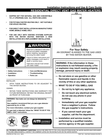
Product Description22Product DescriptionThe boiler is a low temperature gas boiler.GC124 IIThe boiler consists of the following main components:– Ignition module (GC124 II only) and adjustableaquastat1– Boiler jacket and front door2– Boiler block with insulation– BurnerThe ignition module and adjustable aquastat monitorand control all electrical and operational components ofthe boiler.36The boiler jacket prevents energy loss and acts assoundproofing.4The boiler block transfers the heat generated by theburner to the heating water. The insulation reducesenergy loss.5GC124 SP126457 747 000 511-01.0KFig. 1123456Logano GC124 II/SP gas boilerBoiler front doorAquastat (boiler temperature controller)Ignition module (GC124 II only)Boiler block with insulationBurnerBoiler jacketWe reserve the right to make any changes due to technical modifications.Installation and maintenance instructions Gas Boiler Logano GC124 II/SP Issue 07/20067
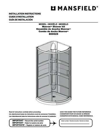
3Dimensions and Connections3Dimensions and Connections23/8VK 1¼"GAS ½"EL ¾"Fig. 2(GAS ½")*RK 1¼"Back, side and front view, measurements in inches* optional connectionConnections (measurements see the following tables):VK Boiler supplyRK Boiler returnEL Boiler drainGAS Gas connectionBoilersizeBoilerinputABVent connectionII/SPMin. relief valvecapacityNumber cheslb/hrQty.US Gal.lbs18/37400013 1/8"8"5"6222.422825/410300016 3/4"8 2/3"5"8632.928732/513250020 3/8"9 1/2"6"11043.4349.5Tab. 1Dimensions/specs for GC124 II and GC124 SPUSER NOTEFor the size and dimensions of the maingas orifices, refer to Î Chapter 18,page 79.Fig. 3Pressure drop/boilerWe reserve the right to make any changes due to technical modifications8Installation and maintenance instructions Gas Boiler Logano GC124 II/SP Issue 07/2006
Scope of delivery44Scope of deliveryz Check packaging upon receipt of delivery for damage.z Check delivery for completeness.ComponentQtyPackagingmethodBoiler, complete11 paletteB-kit components:- 1-1/4" supply manifold- 30 psi relief valve- long shank boiler drain (¾")- ¼" pressure/temperaturegauge- 90 -elbow (1¼" x 1" NPT)- 90 -elbow (1¼" x 1¼" NPT)- 90 -elbow (¾" NPT nipple)- nipple1" NPT- nipple 1¼" NPT11 cardboardbox1Vent damper11 cardboardbox1Circulator with whip11 cardboardbox1Technical documentsTab. 211 plastic packageScope of deliveryOn PaletteAccessoryCleaning BrushTab. 3Qty1Scope of deliveryWe reserve the right to make any changes due to technical modifications.Installation and maintenance instructions Gas Boiler Logano GC124 II/SP Issue 07/20069
55Moving the boilerMoving the boilerThis chapter describes how to move the boiler safelyinto place.SYSTEM DAMAGEDue to uneven and rough surfaces.CAUTION!z Observe the transport diagrams on thepackaging to protect the sensitive components from damage due to rough surfaces. Handle the product with care.USER NOTEz Protect all boiler connections from dirt ifthe boiler is not installed immediatelyfollowing removal from packaging.USER NOTEDispose of the packaging material in anenvironmentally prudent fashion.5.1Moving the boiler with boiler cartMove the boiler with packaging in tact and on its palletas much as possible.z Remove packaging straps and cardboard box frompallet.z Remove screws that secure the boiler base to thewood pallet.z Pick up boiler base from one side and slide to theedge of the pallet. Place a steel pipe as roller underthe boiler base. Place additional steel pipes underthe boiler base and roll the boiler to its final destination.Fig. 4Moving the boiler with rollersWe reserve the right to make any changes due to technical modifications.10Installation and maintenance instructions Gas Boiler Logano GC124 II/SP Issue 07/2006
Moving the boiler5RISK OF INJURYCAUTION!due to improper securing of the boiler during transport.z Use a boiler coart or dolley and strapfor moving the boilerz Secure boiler on the boiler cart.z Remove the front door during lifting ortransport to prevent unintentional opening.z Set the boiler cart or dolley on the front side of theboiler and put a piece of cardboard between the twoto prevent scratches.1z Secure boiler on the boiler cart.z Move boiler to desired location.z Place the boiler at its final postion.Fig. 515.2Moving the boiler with dolley or boiler cart.Additional card board for protection.Lifting and carrying the boilerThe boiler can be picked up at the both long sides of theboiler as shown.RISK OF INJURYdue to carrying heavy loads.CAUTION!z Lift and carry the boiler with at least fourpeople at the designated side panel locations.7 747 000 511-04.0KFig. 6Lifting and carrying the boilerWe reserve the right to make any changes due to technical modifications.Installation and maintenance instructions Gas Boiler Logano GC124 II/SP Issue 07/200611
66Placing the boilerPlacing the boilerThis chapter explains how to place the boiler and position it in the boiler room.SYSTEM DAMAGEdue to frost.CAUTION!z Place the boiler in a frost-free room.The boiler is very heavy when filled with water. Checkthat the floor can bear the weight before installation.6.1ClearancesThe GC124 boiler is approved for closet installation.The following minimum distances must then be maintained:– front: 2",– sides: 2",– behind open draft hood: 6",– above boiler top panel: 30".A space of at least 33 inches is recommended in front ofthe boiler with the door removed to allow sufficient access space for operation and maintenance. When thedoor is closed, a minimum clearance of 2 inches is required at the front and sides, 2 inches clearance is alsorequired for the flue pipe and 30 inches clearance to theceiling. The installation location and the base must besmooth and horizontal.The boiler may be installed ona flammable base, but not on carpet.6.2Leveling the boilerLevel the boiler in both horizontal directions.z Level the boiler using a level and place small wedges(not supplied) for leveling purposes.123Fig. 7123Required clearances in the boiler roomRecommended service clearancesRequired minimum clearancesBurner tray access door with combustion air opening asrequired per ANSI Z.223.1We reserve the right to make any changes due to technical modifications.12Installation and maintenance instructions Gas Boiler Logano GC124 II/SP Issue 07/2006
Boiler installation77Boiler installationThis chapter describes how to install the boiler. This includes the following tasks:– Connecting the heating system– Electrical connection– Gas supply piping connection7.1Preparing for installationz Unpack all boxes and containers and check all partsagainst the packing lists to make sure that everythinghas been supplied.USER NOTEEvery boiler is carefully inspected andtested before it leaves the factory. However, if you discover any damage or missing parts, please inform your supplier immediately. Before disposing of packingmaterial, make sure that no parts are stillin it.USER NOTEFor better access remove the front door.We reserve the right to make any changes due to technical modifications.Installation and maintenance instructions Gas Boiler Logano GC124 II/SP Issue 07/200613
77.2Boiler installationConnecting the heating systemBOILER DAMAGEDue to moisture.CAUTION!3z Protect the components of the gas ignition system from moisture (dripping,spray, rain) during installation of theboiler, during operation and duringmaintenance work (such as replacingthe pump, replacing the control, etc.).SYSTEM DAMAGECAUTION!21Due to overheating as a result of a low water condition.z Note that a boiler installed above thelevel of the heating system must beequipped with a low-water cut-off. Thelow-water cut-off must be installed during installation of the boiler and placedabove the water level in the boiler without any means of shutting the water offbetween the boiler and low watercut-off (Î Fig. 8).224SYSTEM DAMAGECAUTION!Due to high temperature variations in theheating system.z If the boiler is operated in connectionwith a refrigeration system, make surethat the pipes for the refrigerated liquidare connected in parallel to the boilersystem with suitable valves to preventthe refrigerated liquid from entering theboiler.z The piping system of a boiler connected to the heating coils of hydro-air heating systems that may be exposed to thecirculation of cooled air must beequipped with a flow-control valve orsome other automatic system for preventing the boiler water from circulatingby gravity during the cooling cycle.2212Fig. 81234Low-water cut-off installationBoilerRadiatorHeating system with low-water cut-ofHeating system without low-water cut-offWe reserve the right to make any changes due to technical modifications.14Installation and maintenance instructions Gas Boiler Logano GC124 II/SP Issue 07/2006
Boiler installation7Installation of B-kitThe relief valve and the pressure/temperature gauge aremounted on the boiler supply manifold which is attachedto the VK (supply) connection of the boiler (included inB-kit).1Installing boiler supply VK:2z Remove factory installed plastic inserts from boilersupply (VK), boiler return (RK) and boiler drain (EL)connections.3z Install the 1¼"NPT nipple into boiler supply, the 1"NPT nipple into boiler return and ¾" male NPT drainvalve into boiler drain connection.4z Install 90 1¼" x 1¼"NPT on 1¼" NPT supply nippleand face upward and install 90 1¼" x 1"NPT elbowon return nipple and face in desired direction.7z Install GC124 1¼" x 1¼"NPT supply manifold intosupply connection (VK) of the boiler. Do NOT placeon return connection of the boiler!z Install first 90 ¾" street elbow in upper ¾" NPT tapping of GC124 1-1/4" supply manifold and installpressure relief valve into this ¾" tapping. Make sureto orient the discharge of the relief valve horizontally.Install the temperature/pressure gauge in the lower3/4" tapping of the supply manifold.USER NOTEVK58Fig. 9123456789EL6RK9Installation of B-kitPressure relief valve ¾"90 3/4" street elbowGC124 1-1/4" supply manifoldPressure & temperature gauge90 1-1/4" NPT elbow1-1/4" NPT nippleBoiler drain ¾" NPT (backside of boiler)90 1-1/4" x 1" NPT elbow1" NPT nippleInstall the relief valve after the leak test.(Î Chapter 7.5, page 20).The relief valve must be installed in a vertical position.The relief valve must also be installed inaccordance with the requirements of theANSI/ASME Boiler and Pressure VesselCode, Section IV.USER NOTEWe recommend installing a y-strainer (accessory) in the boiler return connection toreduce build-up of debris on the waterside inside the boiler.USER NOTEEnsure compliance with all state and localregulations pertaining to the installation ofboiler systems.We reserve the right to make any changes due to technical modifications.Installation and maintenance instructions Gas Boiler Logano GC124 II/SP Issue 07/200615
7Boiler installationFIRE DANGERdue to exposure to hot water pipes.CAUTION!7.3z Maintain a minimum clearance of twoinches between non-insulated pipescarrying hot water and combustiblewalls and surfaces in the boiler room.A minimum of 1" high quality pipe insulation is required to permit direct contact with combustible surfaces.Electrical connectionsThe electrical connections of the boiler must be made asspecified by the local codes and the current regulationsof the National Electrical Code, ANSI/NFPA–70.The boiler must be grounded as specified by the regulations of the relevant local authorities; otherwise followthe regulations of the National Electrical Code,ANSI/NFPA–70.The boiler is fully functional with the factory installedaquastat and the field installed vent damper and heatingsystem circulation pump.USER NOTEWhen making the electrical connectionsplease observe the following guidelines:z Perform only electrical work, if you possess the required certification for suchwork. When you do not have the required certification, have the electricalwork performed by a certified electrician.z Observe all local and state installationregulations.Power supply connection.Install incoming power to the boiler per local and statecodes.z Install an ON/OFF switch near the boiler per localcode requirements.Fig. 10ON/OFF switch (emergency shutoff switch)We reserve the right to make any changes due to technical modifications.16Installation and maintenance instructions Gas Boiler Logano GC124 II/SP Issue 07/2006
Boiler installation7Description of field installed wiring connectionsusing factory supplied junction box.z Remove two knock-outs from the left side of boilerpanel to route electrical feed and pump power intojunction box.z Route electrical power from the outside into junctionbox.1z Install a metal strain relief for the incoming power lineon outside of left boiler jacket panel. (Î Fig. 12).z Just use supplied wiring nuts and double proper wiring before powering up the boiler.USER NOTEWhen making the electrical connectionsuse only wires that are approved for electrical use.USER NOTERefer to the wiring diagrams on pagesÎ page 80 bis Î page 82 for electricaldetails.2Fig. 111233Electrical junction boxElectrical junction box (Inside of jacket cabinet)Incoming line voltage wiringFurnished wiring nuts.RISK TO LIFEfrom electrical shock.WARNING!z When conducting maintenance worklabel all cables before disconnectingthem.z If cables are connected incorrectly thesystem may not operate correctly withpossibly dangerous consequences.z Check that the heating system functions correctly after any maintenance work.FIRE DANGERWARNING!Fig. 12Strain relief for shielded electrical wiringHot boiler components may damage electrical wiring.z Make sure that all cables are routed inthe ducts or on the boiler insulation.We reserve the right to make any changes due to technical modifications.Installation and maintenance instructions Gas Boiler Logano GC124 II/SP Issue 07/200617
7Boiler installation7.4Fuel gas supply connection7.4.1 Gas connectionsFor the gas pipe diameter required for the installationplease see Î Tab. 4 and Î Tab. 5. Make sure that thepipe fitting has the correct thread size.1Make sure that a sediment trap is installed at the inlet forthe gas supply pipe to the boiler. A manual stop valvemust be installed outside the boiler jacket if required bythe local code. We recommend installing a manualshut-off valve in the main gas pipe to the boiler. The gaspipe must be fastened outside the boiler.2The local codes must be observed during installation ofthe gas piping connections, otherwise the regulations ofthe National Fuel Gas Code, ANSI Z 223.1 must be followed.3z Install gas piping without any undue stress on thepiping.z The Commonwealth of Massachusettes prohibits theuse of copper tubing for the gas line.DANGER OF EXPLOSIONWARNING!Leakage from the gas pipes and gasconnections may cause an explosion.Fig. 13123Gas piping connection to gas valve – right or left sideGas feedManual shut-off valveSediment trapz Use soap solution to find leaks.Gas carrying capacity (refer to technical manual Î Chapter 18, page 79)Length Gas pipe supply volume in cubic feet of gasof pipeper hour1in feet1/23/411 1/41 4510038791603054801503164120250380Tab. 51Gas pipe supply volumeNominaldiameter ofiron pipe(inches)1/23/411 1/41 1/2Tab. 4Equivalent lengths for pipe fittings infeetPipe fitting type90 Shut-offGasT-pieceanglevalveshut-offEquivalent lengths in 82.154.08.00.92.50Equivalent lengths for pipe fittingsMaximum gas supply volume in cubic feet per hour, based ona specific gas weight of 0.60 and a gas pressure of 0.5 psi or lessand a pressure gradient corresponding to a water column of0.3 inches.We reserve the right to make any changes due to technical modifications.18Installation and maintenance instructions Gas Boiler Logano GC124 II/SP Issue 07/2006
Boiler installation7Disconnect the boiler with the manual shut-off valve andphysically separate the boiler from the gas piping if thegas piping system is pressure tested with a test pressuregreater than 1/2 psi.If the gas supply pipe system is pressure tested at a testpressure of 1/2 psi or less, it is sufficient to disconnectthe boiler from the gas pipe system by closing the manual shut-off valve.Use only sealant that is resistant to corrosion by LPG forpipe connection. Only a small amount of sealant must beapplied to the external thread of the pipe connections.If you wish to convert the boiler to propane, please contact Buderus for the required conversion components.Do not attempt to convert the boiler without the approved Buderus propane conversion parts and the relevant technical documentation. The technical d
Installation and maintenance instructions Gas Boiler Logano GC124 II/SP † Issue 07/2006 1.3.2 Installation notes 1.3.3 Information on the boiler room CAUTION! SYSTEM DAMAGE due to incorrect installation. zObserve all current standards and guidelines applicable to the installation and operation of the boiler heating