Transcription
11th International Conference on Vibration ProblemsZ. Dimitrovová et al. (eds.)Lisbon, Portugal, 9-12 September 2013FINITE ELEMEMT ANALYSIS OF THE DYNAMIC BEHAVIOUR OFTRANSMISSION LINE CONDUCTORS USING MATLABE. E. Ojo*1 and S. Shindin212Vibration Research and Testing Centre, University of KwaZulu-Natal, Durban, South AfricaSchool of Mathematical Sciences, University of KwaZulu-Natal Durban, South AfricaKeywords: Conductor Mechanical Vibration, Analytical Model, Finite Element Method,MATLAB Software, Line Contact, Stiffness Matrix, Self-damping,Abstract. The dynamic behaviour of power line cables have been a source of interest toresearchers ever since the phenomenon was first noticed in the 1920s. Conductor oscillationis mostly caused by the dynamic forces of nature such as wind loading [1]. This imposes aperiodic force on the conductors which is highly undesirable. It is therefore important forengineers to account for the possible effect of the wind loading when designing the powerline.Investigations have shown that modeling the exact dynamic behaviour of a conductor is verydifficult. Based on this fact, getting the exact analytical solution to conductor vibration isdifficult, which is almost impossible, hence the numerical approximation becomes an option.This paper presents the developed finite element method used to analyse the dynamicbehaviour of transmission line conductors. The developed finite element method (FEM) isimplemented on MATLAB.The numerical analysis using MATLAB that is presented in this paper is used to simulate theresponse of the conductor when subjected to external loading in time domain. The simulationis used to analyse the transverse vibration of the conductor. The formulation of the stiffnessand load vector is done and the results obtained is used to evaluate the conductor‟ internalenergy dissipation. This finite element solution is compared with the results documented byC. Hardy [2]. This numerical simulation is used to investigate the effects of varying the axialtension on energy dissipation within the strands. Hence, this evolved in physicallyappropriate energy characterization process that can be used to evaluate the conductor selfdamping with respect to line contact.
Ojo,. ShindinE. E.S1. Theoretical BackgroundThe investigation of the mechanics of power line conductors have been a subject of bothacademic and industrial research ever since the phenomenon was first noticed. Most ofearly research in this field, investigated the global behaviour of the conductor, in whichthe conductor was treated as a solid, homogeneous continuous system. Several of thesemodels developed for conductors, model the conductor as a beam or taut string and areavailable in literatures. These developed models are used to predict the global response ofthe conductors as a means of determining its natural frequencies, modes shapes anddamping.R. Claren and G. Diana [3] developed the mathematical model for the conductortransverse vibration using the concept of the conductor‟s principal modes. The authors[4-6] investigated this phenomenon in the aspect of fluid-solid dynamic excitation, byconducting experiments in wind tunnel. They investigated how and the amount of forceimpacted that causes the conductor oscillation. The findings from these wind tunnelexperiments have been used to develop emperical formulae used to determine the windinput power to the conductor. Also the authors [7-11] have all come up with variousmodels to determine the conductor damping and the number of vibration absorbersneeded on the line to curtail the effect of mechanical oscillation on the line conductors.Unlike regarding a conductor as a solid system, a more realistic approach would be toconsider a conductor as a composite consisting of an assembly of a number of helicalstrands. In regarding it as a composite structure, help to explain why the dynamics ofcables tends to exhibits a non-linearity. This is because conductor dynamics is a functionof parameters that has to do with its geometry and this proffers the reason why it isimpossible to obtain an exert analytical solution. Therefore, the approach of modeling theconductor as a single, homogenous system is incapable of addressing local phenomenonwithin the strands like contact, strand slippage and frictional effects when under theinfluence of tension and bending.Some recent investigations have employed the discretized approach in analyzing cables.In [12] the author carried out the analytical analysis of rope. In the work by R. E Hobbsand M. Raoof [13], the various forms of contacts within the cable geometry wereexplained. These forms of contact in a cable can be used to identify where frictionaleffects which can be used to analyse stick and slip process within the Cables. R. H.Knapp [14] analysed the cables helically using the contact deformation and frictioneffects to calculate stresses. On the bases of stick and slip conditions of strands, inreference [15], the author presented a novel and more realistic model to determinebending stiffness of a conductor under both axial and bending loads. He developed thesecant bending stiffness model that can be used to determine the variable bendingstiffness under the conditions of inter-layer friction and slip as a function of displacementand curvature. This model established the fact that the bending stiffness value at anypoint along the conductor varies non-linearly with the curvature. C. Hardy [2] explainedhow to evaluate energy dissipation along line contacts. This paper presents, first in the seriesof investigations into the concept of conductor self-damping. A FEM for addressing theconductor dynamic behaviour as a function of its inter-strand line contact is developedand implemented on Matlab software. This numerical method focuses mainly on thework documented by C. Hardy [2] and this entails treating the conductor as composite2
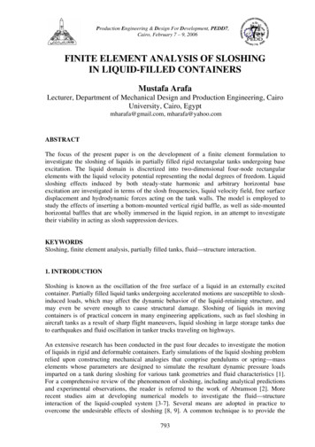
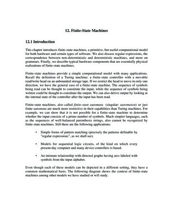
Ojo,. ShindinE. E.Sstructure formed by the assembly of helical strands layers over the core with the analysisof the inter-strand line contact areas, the effects of friction and slip are analyzed duringthe periodic motion. In the quest for developing this finite element simulation for theconductor, it is first of all imperative to present the geometric description of theconductor and concepts that will be used for the formulation.2 Stranded Bare ConductorTransmission line conductor is made up of single or multiple layer(s) of strands. Thestrand is the basic structure of the conductor; whose arrangements comprises of thecentral core and the helically curved strand. The stranded conductor is treated ascomposite structure of a collection of strands, arranged in layers and each layer isconstituted by helically wound profile with a lay angle which is alternated in successivelayers. For a single-layered conductor as shown in figure 1, comprise of a centre corestrand and a layer of 6-strand.YYXZZFigure 1: single layer conductor2.1 Description of a Stranded Bare ConductorConsider figure 2, a stranded bare conductor with cross-section AT ; consist of i-layers(i 1, 2,., N ) , each layer made of a number of strands of radius ri with lay angle i ,wrapped over the centrally located core strand, of radius r0. Each particular layer consistsof m number of strands and the position of each strand is defined as m(i, j ) , wherej ( j 1, 2,., m) defines the strand position from the z-axis in the anti-clockwisedirection. The distances of each layer of strand at origin and the distance along thecurvilinear axis of helix from the conductor neutral axis are:2 Xhi j Ri j sin( i j ) and hi ( X ) Ri sin( i j ) .(1) Where i j is the angular position from the z-axis in the anti-clockwise direction, Ri j isthe radius between layers and Ri radius of the circular path that passes through the centreof strands located at i-layer and both can be calculated byN 1Ri j r0 ( k ) d ii 1Where k { 10i 0i 1, 2, .N 1Ri r0 d i rN . (2)i 13
Ojo,. ShindinE. E.SYZFigure 2: Conductor Cross-section2.2 Inter-strand ContactsThe power line cables when strung on the towers, the ends are subjected to tensile forceand when allowed to rest under the influence of gravity forms a centenary profile. Thiscondition creates a compact form of the conductor giving rise to some form of contactsbetween strands and with the core. As mentioned before, in [13] the various forms ofcontacts within the cable geometry were identified. The authors identified two forms ofcontacts: the line and the point contacts.The line contact occurs between the parallel layered helical strands of the same layer.This form of contact also exists between the first layer and the core. Thus, this form ofwire-wire contact, exist between wires in the same layer are, and between first layers withthe core. The point or trellis contact occurs due the helical arrangement of strands. Dueto the opposite lay angle, alternate layer strands crosses each other producing a point ortrellis contact i.e. a layer-layer contact where the strand in the one layer touches onlythose in adjacent layers at a point. The knowledge of the form of force, deformation andstress in the area contact is very important because due to friction.Under the stick conditions both strands exert equal and opposite force at the region ofcontacts. During bending resulting from dynamic loading, the frictional force isovercome resulting in relative sliding between the strands in the area of contacts. Thissliding can have effect on the dynamic behaviour of the conductor because energydissipation does occur in the contact areas.1 Conductor DampingTransmission lines when exposed to the dynamic forces of nature the cables experiencestransverse vibrations. The energy on the cable is dissipated internally and external byvibration absorber if present on the line. Conductor self-damping (internally dissipation)can be attributed to two main sources.4
Ojo,. ShindinE. E.SConductors can damp out this energy by internal energy losses at microscopic(molecular) level within the core and individual strands of the conductor and this knownas metallurgical or material damping [1]. Also when the conductor flexes, the strands ofthe conductor slip against each other; this relative motion generates frictional forces thatprovide damping [2]. The combination of these energy dissipative processes by aconductor is known as conductor self-damping. During bending, the energy dissipationdue to frictional effects around the area of contacts induced by the sinusoidal forcingfunction coupled with the material damping tends to limit the amplitude of vibration.Reference [2] inferred that energy dissipation during the slip regime mainly account forthe conductor self-damping.2 Conductor’s Stress and StrainConductors are strung at both ends with axial tensioned which is a percentage of itsultimate tensile strength. This axial loading constrains the strands to have one form ofcontacts, where resistive frictional force tends to prevents displacements. This axial forceresult to some form of stresses along the contacts areas. Based on the fact that energydissipation is caused by sliding along the areas of contacts where the frictional forces isovercome, in this paper the evaluation of damping is focused on flexure during the slipregime a similar approach adopted in [2] .Hence, for the evaluation of energy dissipation, the stresses due to line contacts areconsidered and for now application is for singled-layered conductors.The strands in an axially tensioned conductor are subjected to tensile, bending andtorsional stresses but mainly to tensile stress [16]. Neglecting bending and torsionaleffects, the tensile stress acting across the section of the conductor can be evaluated asS x . (3)ATN Where AT is the conductor cross section and can calculated as AT r0 d i i 1 Each individual strand is assumed to be subject to the same tensile force given by [15]Zi j Ei Ai cos 2 i.S Ei Ai cos3 i. (4)all strandsWhere E is the Young modulus, Ai j is the strand cross section area, i is the layer layangle, S is the axial tensionThe tensile stress acting on the individual strandsZi j i j . (5)Ai jNeglecting the effect of Poisson ratio, the strain acting along the line contact between thestrand and the core [2]d 2Y hi j Ei i j . (6)dX 25
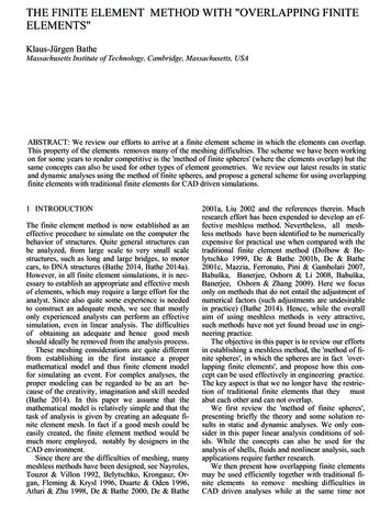
Ojo,. ShindinE. E.SFor a laminar wind flow across, the loading causes the power line cables experiencestransverse sinusoidal displacement which is known as Aeolian vibration. Thedisplacement of this sinusoidal function as can be defined as 2 X Y Ymax sin . (7) The axial strain due to the axial loading along the line contacts as function curve helicalpath can be determine assT ( s) . (8) A ( ).q d EAi 0The pressure q can be evaluated by [17]q Z i j sin 2 i . (9)Ri jFor sinusoidal displacement according to [2] can the friction coefficient is evaluated asRcY ( EA) cos 3 2 ( x) q 3 2 X 2 X 2 X 2 X i j sin i j cos sin . (10) cos P P p p3 Finite Element ModelThe objective of this study is to develop a finite element simulation to evaluate theparameters such as the displacement field. In the formulation, only the axial strain isconsidered and this is similar to the finite element for a bar element. Using the barelement as shown in figure 3, taking into account the sinusoidal axial displacement forthe two-node bar element.u1u1F1Figure 3: The Bar ElementF2The strain x can related to the axial displacement u as x dudx . (11)The axial displacement is interpolated byu N1 ( )u1 N 2 ( )u 2 . (12)Where the shape functions are defined asN 1 ( ) 1(1 ) ;2N 2 ( ) 1(1 )2The resultant tensile for on the strands can be evaluated asf 2 f1 EA l EA u 2 u1 ll6
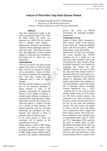
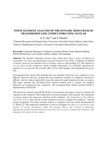
Ojo,. ShindinE. E.SThe above equation can be written in matrix for as followsEA EA ll u1 f1 EA EA f u 2 ll From equation (8) , the axial force acting the strand can be determined bysZ i j ( s) EA ( ).q d . (13)0Hence,EA cos 2 u 2 u1 qEA ( X ) cos 3 l 1 1 1 u1 3EA cos 2 qEA X ()cos 1 1 1 u 2 . (14)The finite element formulation is expressed on the finite element equilibrium and theforce-displacement relation is given by K {u} { f } . (15)Where [K] the stiffness matrix, {u} is the vector displacements and {f} is the force vectorand displacements {u} are interpolated over the whole conductor strand as {u} [N]T{d}4 Matlab ImplementationA MATLAB code [18] was used to simulate above finite element equation for the barelement. The code was modified to include the sinusoidal forcing function. Theimplementation was used to simulate this numerical problem developed above for thevibrating conductor. The implementation was done for single layer conductors. Thismodel was formed by the assembly of the finite element equation into a global matrix inthe form of stiffness and force vector. In assembling all the finite elements equationsrequires the satisfaction of the boundary conditions in which displacements areconstrained at both end of the strand. The code was simulated to find the solution to thedisplacement field developed from FEM.Another Matlab code was developed in which the displacement field severs as inputvariable to generate the hysteresis loop. This computer program simulation was used togenerate loops for three different axial tensions. Using the MATLAB results, the workthat is documented in [19] was verified in which the author inferred that the conductordamping decreases with increase in axial tension.5 ResultsThe numerical technique was used to solve the assembled FEM equation. The systemequation [K]{d} {f} was solved for the system displacements {d}. In [2] the authordraw the inference that the non-linearity in strand axial movement result in closedhysteresis loops. He gave a classsical explanation on how the loop can be use to7
Ojo,. ShindinE. E.Sdetermermine energy per cylce. This concept was varied by using Matlab code generatthe hysteresis as show below, and comparison was made.ABFigure 4: A-Hysteresis loop from [2] and B- hysteresis loop from MatlabThe data for the single layer conductor; the family of AAAC- 6201 (Akron, Alton, Ames)whose data are in table 1 were used to for the .22612455.020Diameter Table 1.Single layer conductor AAAC- 6201[20]This numerical simulation was used to investigate the effects of varying the axial tensionon energy dissipation using the conductors‟ data in the table 1 above. The implementationwas done for these conductors with their axial tensions set at 15, 20, 25 and 30% ofultimate tensile strength. The results are shown in table 2.Axial Tension(% UTS)Energy Dissipation per TABLE 2: The energy dissipation at various axial tensions8
Ojo,. ShindinE. E.S6 ConclusionThe evaluation of conductor damping is a complex problem. In this paper, finite elementimplementation of an axially displaced bar model when subjected to bending waspresented. This was used to simulate the axial displacement of conductor when subjectedto both tensile and bending. This model was used to determine the amount of energydissipated along the line contact. Using the Matlab finite element results a comparisonwas made with that documented [2] and this shows a good agreement.This was extended to determine the energy dissipation at three different conductorstringing tensions this done with respect to the percentage of its UTS. The results ofvarying the axial tension established the fact that damping decreases with the increase intension .The parameters obtained from the above, to some degree accuracy can be used toevaluate conductors damping due to line contacts.Presently, this work is being extended to include an implementation of the damping dueto point contacts which the analysis of this form of contact can be found in a more recentpaper by C.B. Rawlins [21]. This will include the formulation that will be applicable tomultilayer conductors. To enhance the reliability of the finite element model that will bedeveloped, the conductor will be treated as composite beam which is more realistic withrespect to the conductor structure as compared to solid beam which is mostly found inseveral literatures.REFERENCES[1] EPRI “Transmission Line Reference Book: Wind-Induced Conductor Motion”Final Report, November, 2006[2] C. Hardy, “Analysis of Self-damping Characteristic of Stranded Cables inTransverse Vibrations” CSME Mechanical Engineering Forum, 1990[3] R. Claren and G Diana, “Mathematical Analysis of Transmission Line Vibration”IEEE transactions on power apparatus and systems, vol. pas-88 No. 12, December,1968[4] F.B Faquharon and R.E McHugh, “Wind Tunnel Investigation of conductorVibration of Rigid Model” IEEE, Transaction Paper, Pp. 871-7, October 1956[5] G. Diana and M. Falco, “On the Forces Transmitted to a Vibrating Cylinder by aBlowing Fliud” Meccanica, vol. 6 pp. 9-22, 1971[6] C.B. Rawlins, “Wind Tunnel measurement of the Power Imparted to a ModelVibrating Conductor” IEEE Transactions of Power Apparatus & Systems, Vol,PAS-102, No 4, April, 1983, pp 963-972[7] Cigrè Study Committee 22-Working Group o1, “Report on Aeolian Vibration”Electra, no 124, pp-101, May 1989[8] J. Vecchiarelli, I.G. Currie and D.G. Havard, “Computational Analysis of AeolianConductor Vibration with a Stockbridge-type Damper” Journal of fluids andStructures 14, 489-509, 2000[9] L. Möcks . and J. Schmidt , “Survey on measurements of mechanical self-dampingof ACSR conductors” CIGRESC22-89 (WG-11)TF1-2, 19899
Ojo,. ShindinE. E.S[10] P. Hagedorn, “On the Computation of Damped Wind Excited Vibrations ofOverhead Transmission lines” Journal of Sound and Vibration 83, 253–271, 1982[11] N. Barbieri, O.H. Souza Jr., R. Barbieri, “Dynamical analysis of transmission linecables, Part 1—Linear Theory”, Mechanical and Systems Signal Processing 18 (3)(659–669), 2004[12] G.A. Costello „Analytical investigation of wire rope‟, Appl. Mech. Rev.,31(7),pp.897-900 1978[13] R.E. Hobbs, and M. Raoof, “Behaviour of Cables under Dynamic or Repeatedloading”, Journal of Constructional Steel Research, 39(1), pp.31-50, 1996[14] R.H. Knapp „Helical wire stresses in bent cables‟, J. Offshore Mech. ArcticEng.,110, pp.55-61. 1988[15] K.O. Papailiou, “On the Bending Stiffness of Transmission Line Conductors” 6102Malters, Switzerland, IEEE 1996[16] K. Feryer “Wire Ropes Tension, Endurance and Reliability” Springer, 2010[17] F.H. Hruska, “Radial Forces in Wire Ropes”, Wire and Wire Products, Vol 27,No5pp. 459-63,1952[18] Y.W. Kwon and H. Bang, “Finite Element Method using Matlab” 2nd EditionCRC Press, 1997.[19] E. E. Ojo “Dynamic Characteristics of Bare Conductor” Msc in ElectricalEngineering Dissertation, University of KwaZulu-Natal, 2011[20] Southwire, Cable catalogue[21] C. B. Rawlins, “Flexural self-damping in overhead electrical transmissionconductors” Journal of Sound and Vibration Vol. 323, Issues 1–2, 5 Pages 232–256June 2009,10
This paper presents the developed finite element method used to analyse the dynamic behaviour of transmission line conductors. The developed finite element method (FEM) is . and implemented on Matlab software. This numerical method focuses mainly on the work documented by C. Hardy [2] and this entails treating the conductor as composite .