Transcription
truVision DVR 31 User ManualP/N 1072981 REV A ISS 06MAR12
CopyrightTrademarks and patents 2012 UTC Fire & Security. All rights reserved.Interlogix, the truVision DVR 31 and the truVision Brand and logo aretrademarks of UTC Fire & Security.Other trade names used in this document may be trademarks orregistered trademarks of the manufacturers or vendors of the respectiveproducts.ManufacturerUTC Fire & Security Americas Corporation, Inc.2955 Red Hill Avenue, Costa Mesa, CA 92626-5923, USAAuthorized EU manufacturing representative:UTC Fire & Security B.V.Kelvinstraat 7, 6003 DH Weert, NetherlandsVersionCertificationFCC complianceCanadaACMA complianceEuropean Union directivesThis document applies to truVision DVR 31 version 00.20.N4131Class A: This equipment has been tested and found to comply with thelimits for a Class A digital device, pursuant to part 15 of the FCCRules. These limits are designed to provide reasonable protectionagainst harmful interference when the equipment is operated in acommercial environment. This equipment generates, uses, and canradiate radio frequency energy and, if not installed and used inaccordance with the instruction manual, may cause harmfulinterference to radio communications. Operation of this equipment ina residential area is likely to cause harmful interference in whichcase the user will be required to correct the interference at his ownexpense.This Class A digital apparatus complies with Canadian ICES-003.Cet appareil numérique de la classe A est conforme à la norme NMB003 du Canada.Notice! This is a Class A product. In a domestic environment thisproduct may cause radio interference in which case the user may berequired to take adequate measures.2004/108/EC (EMC directive): Hereby, UTC Fire & Security declaresthat this device is in compliance with the essential requirements andother relevant provisions of Directive 2004/108/EC2002/96/EC (WEEE directive): Products marked with this symbol cannotbe disposed of as unsorted municipal waste in the European Union. Forproper recycling, return this product to your local supplier upon thepurchase of equivalent new equipment, or dispose of it at designatedcollection points. For more information see: www.recyclethis.info.Contact informationCustomer supportwww.utcfireandsecurity.com or ort
ContentChapter 1 Product Introduction 1Product Overview 2Chapter 2 Installation 3Installation environment 4Unpacking the DVR 31 and its accessories 4HDD capacity 5Back panel overview 6Connecting devices to the unit 7Chapter 3 Operating instructions 9Control interfaces 10Controlling the DVR 31 10Front panel overview 11Using the mouse 12Using the IR remote control 15Operating modes 17Main menu overview 17Chapter 4 Basic operation 23Turning on the DVR 31 24Live mode 24Spot monitor 26Logging on 27Logging off 28Controlling a PTZ camera 28Playing back video 30Archiving recorded files 36Turning off the DVR 31 41Chapter 5 Using the Web browser 43Overview 44Windows Vista and 7 users 45Browser connections 46Using the Web browser to configure the device 46Searching and playing recorded video 47Live dual streaming 47Bandwidth throttle management 48Controlling a PTZ camera in the Web browser 48truVision DVR 31 User Manuali
Chapter 6 Advanced setup 51Managing users 53Configuring cameras 57Configuring recording and schedule settings 61Alarm settings 66Network settings 69Display settings 73Chapter 7 System settings 77Overview 78System date and time 79Audio and remote 80RS-485 settings 80RS-232 settings 81Mouse Sensitivity settings 81Hard drive settings 81Importing and exporting configuration settings 82System log 82Upgrading the firmware 85Appendix A Specifications and Troubleshooting 87Product specifications 88Product specifications 88HDMI Compatibility List* 89HDMI Incompatibility List 89Battery removal 90Troubleshooting 90Appendix B Factory defaults 91Menu defaults 92Network defaults 92Appendix C Warranty and support 93Warranty information 94Contacting support 94Appendix D KTD-405 keyboard mapping 95DVR 31 to KTD-405 keyboard mapping 96Index 97iitruVision DVR 31 User Manual
Chapter 1Product IntroductionSummaryThis chapter provides an overview of the DVR 31, including its features andfunctions.ContentProduct overview 2truVision DVR 31 User Manual1
Chapter 1: Product IntroductionProduct OverviewThis is the truVision DVR 31 User Manual for models: TVR-3108-1T TVR-3108-2T TVR-3116-2T TVR-3116-4T TVR-3116-6TThe truVision DVR 31 is a network digital video recorder developed for digitalsurveillance. The truVision DVR 31 uses an embedded microcontroller unit(MCU) and Linux operating system, combining the most advanced technology invideo and audio encoding/decoding, hard disk recording, and TCP/IPcommunication. The DVR’s firmware is stored directly into the memory, making itmore stable and reliable.The truVision DVR 31 is an integrated digital video recorder that combines thefeatures of a time-lapse audio/video recorder, a multiplexer, and a video server tocreate a single security solution.The DVR 31’s pentaplex operation enables users to view live video, search andplay back any recorded video by date and time or by event, and back up theconfiguration and video data, without interrupting the ongoing DVR recordingprocess.In addition to the new H.264 compression mode, the DVR’s graphical userinterface also optimizes the monitoring controls of the unit.The DVR 31 comes with remote viewing and configuration software alreadyinstalled. This software includes a Web browser plug-in, allowing users to viewlive or recorded video images, and enabling remote configuration. The remotesoftware is stored in the DVR 31 and deployed over a LAN, WAN, or Internetconnection to remote Windows-based computers. This simplifies the installationand maintenance of the software components because all remote users areusing the same software, which comes from the unit.2truVision DVR 31 User Manual
Chapter 2InstallationSummaryThis chapter provides information on how to install and connect peripherals toyour device.ContentInstallation environment 4Unpacking the DVR 31 and its accessories 4HDD capacity 5Back panel overview 6Connecting devices to the unit 7Connecting required devices 8Connecting external devices 8truVision DVR 31 User Manual3
Chapter 2: InstallationInstallation environmentWhen installing your product, consider these factors: VentilationTemperatureMoistureChassis loadVentilation: Do not block any ventilation openings. Install in accordance with themanufacturer’s instructions. Ensure that the location planned for the installationof the unit is well ventilated.Temperature: Consider the DVR 31’s operating temperature (32 to 104 F, 0 to40 C) and humidity specifications (10 to 90% relative, noncondensing) beforechoosing an installation location. Extremes of heat or cold beyond the specifiedoperating temperature limits may reduce the life expectancy of the DVR 31. Donot install the DVR 31 on top of other hot equipment. Leave 1.75 inches (44 mm)of space between rack mounted DVR 31 units.Moisture: Do not use the unit near water. Moisture can damage the internalcomponents. To reduce the risk of fire or electric shock, do not expose this unit torain or moisture.Chassis: Equipment weighing less than 35 lbs (15.9 kg) may be placed on top ofthe DVR 31 only if the DVR 31 is placed on a shelf and not rack mounted.Be sure to power off the unit before making any connections. In order to preventthe unit from losing data and system damage that may be caused by suddenpower, use of an uninterruptible power supply is highly recommended.Note: Do not remove the rubber feet, and always leave a space for air ventilationon the unit’s bottom side.Unpacking the DVR 31 and its accessoriesWhen you receive the product, check the package and contents for damage, andverify that all items are included. There is an item list included in the package. Ifany of the items are damaged or missing, please contact your local supplier.Items shipped with the product include: truVision DVR 31 IR (infrared) remote control Two AAA batteries for the remote control4truVision DVR 31 User Manual
Chapter 2: Installation USB mouse Power cord Rack mount kit (left and right brackets, screws) Terminal blocks truVision DVR 31 Quick Start Guide truVision DVR 31 Quick ChartThe support CD includes the following items: truVision DVR 31 User Manual truVision DVR 31 Quick Start Guide truVision DVR 31 Quick Chart Video player application Record duration calculatorHDD capacityStorage capacity for the truVision DVR 31 varies depending on the model. Referto Table 1 below for more information.Table 1: truVision DVR 31 model typesModelModel numberDescription8 channel modelTVR-3108-1TtruVision DVR Model 31, 8 ch, 1 TBTVR-3108-2TtruVision DVR Model 31, 8 ch, 2 TBTVR-3116-1TtruVision DVR Model 31, 16ch, 1 TBTVR-3116-2TtruVision DVR Model 31, 16ch, 2 TBTVR-3116-4TtruVision DVR Model 31, 16ch, 4 TBTVR-3116-6TtruVision DVR Model 31, 16ch, 6 TB16 channel modeltruVision DVR 31 User Manual5
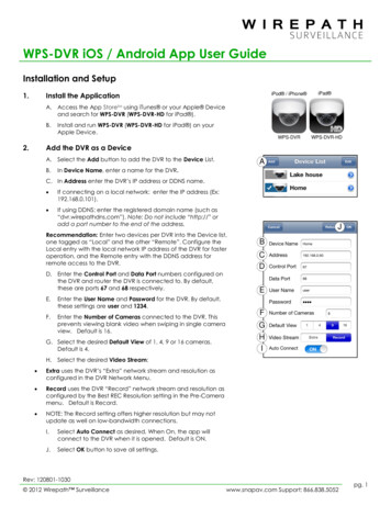
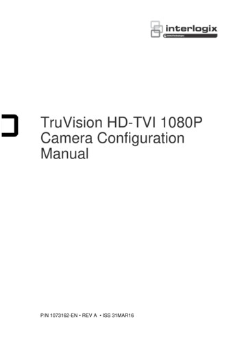
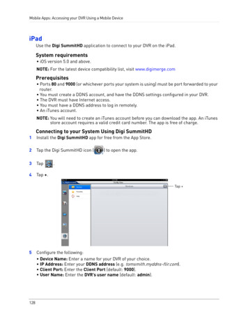
Chapter 2: InstallationBack panel overviewFigure 1 below shows the back panel controls and connectors on a typicaltruVision DVR 31.Figure 1: DVR 31 back panel1.Video out2.Video in (top row, loop out bottom row)3.Audio out4.S-video port5.Audio in6.Digital video output7.Alarm I/O and RS-4858.Network Attached Storage (NAS) port (This device iscurrently not supported.)9.LAN port10. USB port11. RS-232 port12. VGA output13. Power switch14. Power input6truVision DVR 31 User Manual
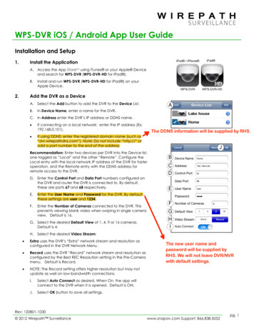
Chapter 2: InstallationConnecting devices to the unitUse Figure 2 below as a visual guide to connect the various peripherals to theDVR 31.Figure 2: Back panel connection diagram1.Connect up to two CCTV monitors (main and spot)and/or Y/C (S-video)2.Connect up to 16 cameras3.Connect to speakers for audio output10. Connect to a network4.Connect to audio input (available for each camera)11. Connect to USB device5.Connect to a monitor that displays digital video(HDMI)12. Connect to a point-of-sale (POS) device6.Connect to a PTZ control7.Alarm output8.Connect to alarm input cables9.Connect to a network attached storage (NAS) device(This device is currently not supported)13. Connect to VGA monitor14. Connect to the power cordNote: DVR 31 display options are: 800 x 600, 1024 x 768, 1280 x 1024, 720P,and 1080P. If looping video, ensure that the Termination option (Main Menu Cameras Adjust Video) is disabled.truVision DVR 31 User Manual7
Chapter 2: InstallationConnecting required devicesBefore powering up the unit, cameras and a main monitor should be connectedto the unit for basic operation. If needed, connect a spot monitor for displayingfull screen video of all installed cameras in sequence.Note: You can attach an extension to the RS-485 port on the back panel.Connecting external devicesWhen connecting external devices to include as part of the entire system, suchas a USB drive or any other USB devices, connect those devices only when theunit displays live view. The DVR 31 recognizes external devices only after theunit has gone through the initialization process.8truVision DVR 31 User Manual
Chapter 3Operating instructionsSummaryThis chapter describes the how to control and navigate through the DVR 31’smenus and options.ContentControl interfaces 10Controlling the DVR 31 10Front panel overview 11Status LEDs 12Using the mouse 12Mouse toolbar 13Using the IR remote control 15Controlling multiple DVRs with one remote control 16Operating modes 17Main menu overview 17Main menu commands 18Using the main menu 19Navigating through dialog screens 19Using the virtual keyboard 20Exiting the main menu 21truVision DVR 31 User Manual9
Chapter 3: Operating instructionsControl interfacesThe DVR 31 has three control interfaces: Built-in interface Display interface Web browser interfaceBuilt-in interface. The built-in interface is displayed on the monitor output. Itconsists of a main menu and several dialog screens that let you configure andcontrol the device. You can invoke the built-in interface using the front panel,remote control, or mouse.Display interface. The display interface consists of various toolboxes thatappear on top of the monitor image. These let you control live or playback videowhile in PTZ or playback mode. You can invoke the display interface from thebuilt-in interface screens or from the mouse toolbar. The controls in any toolboxcan be operated using the front panel, remote control, and mouse.Web browser. The Web browser interface uses Internet Explorer to simulate thedisplay and control functions of the VGA monitor on a remote PC. The Webbrowser interface can only be accessed by a PC with Internet access. SeeChapter 5 “Using the Web browser” on page 43 for more information on the Webbrowser interface.Controlling the DVR 31You can control the DVR 31 using: Front panel control IR remote control Mouse controlFront panel control. Use the directional arrow buttons to select a command,option, or button on a screen. Use the Enter button to confirm a selection. Usethe Esc button to cancel a selection.IR remote control. Use the directional arrow buttons to select a command,option, or button on a screen. Use the OK button to confirm a selection. Use theEsc button to cancel a selection.Mouse. Move the pointer to a command, option, or button on a screen. Click(with the left mouse button) to confirm a selection. Right-click to save and exit ascreen.10truVision DVR 31 User Manual
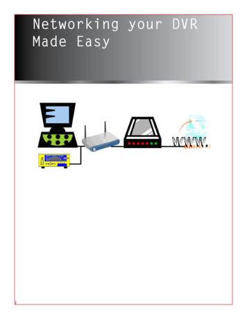
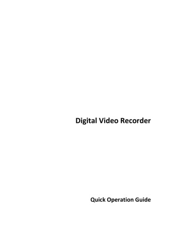
Chapter 3: Operating instructionsYou can use your preferred control method for any procedure, but in most caseswe describe procedures using mouse terminology. Optional control methods aregiven only when they differ substantially from mouse control methods.Front panel overviewThe buttons on the front panel control all DVR 31 functions and set theprogrammable functions. The LED indicators light up or flash to alert you ofvarious conditions.Figure 3: Front panelTable 2: Front panel button descriptionsItemNameDescription1Numeric buttonsDisplay the corresponding video in full screen while inboth live and playback mode. The number of the buttoncorresponds to the camera number. Press and hold anumeric button for two seconds to display thecorresponding video on the spot monitor.While in PTZ mode, press the 1 button to access theSet/Go Preset menu.2Menu and Esc controlsPress Esc to exit a screen or cancel a selection. PressMenu to display the main menu.3Directional Controls AndEnter buttonUse arrow buttons as directional keys in zoom mode.truVision DVR 31 User ManualWhile in a setup menu, use the Left or Right Arrow keysto navigate through fields. Use the Up or Down Arrowkeys to change the value of a selected field. PressEnter to confirm the selection or display additionalscreens.11
Chapter 3: Operating instructionsItemNameDescription4USB portsConnect USB devices.5CD/DVD driveInsert media for archiving.6Archive buttonBegin archiving or displays the Archive screen.Press once to begin copying a video segment for exportwhile in playback mode. Press again to stop copying.See “Archiving recorded files” on page 36 for moreinformation.7Status LEDsDisplay device status and conditions. See “StatusLEDs” below for more information.8Function buttonsChange the DVR 31 operating mode. For example,press PTZ to go into PTZ mode. See “Operatingmodes” on page 17 for more information.9Playback controlsControl video playback speed.Status LEDsThe LEDs on the front panel of the DVR are described as follows.Table 3: Status LED descriptionsLEDRECNameDescriptionPowerSteady indicates that the correct power is connected to the unit.NetworkBlinking indicates that the DVR is connected to a network.AlarmSteady indicates that an alarm is triggered.RecordBlinking indicates that the DVR 31 is recording. Steady indicateshard drive failure.Using the mouseUse the USB mouse provided with the DVR 31 to carry out the same operationsas the front panel and remote control. Connect the mouse to the DVR 31 byplugging the mouse USB connector into one of the USB ports on the front panel.The mouse is immediately operational and the pointer should appear.Click the left mouse button to enter or confirm a selection. This is similar topressing Enter button on the front panel. Click the right mouse button to the exitsetup menus and save the settings. Use the scroll wheel to change values.Mouse sensitivity can be adjusted in the Systems menu.12truVision DVR 31 User Manual
Chapter 3: Operating instructionsMouse toolbarWhile in live, playback, or sequence mode, point to the date and time to displaythe mouse toolbar, as shown in Figure 4 below.Note: To move the mouse toolbar to a different position, click and drag the dateand time display.Figure 4: Mouse toolbarMouse toolbar iconsTable 4 below describes the icons that appear on the mouse toolbar.Table 4: Mouse toolbar iconsIconDescriptionUser is logged in. Numerical value indicates the user’s access level. User icon witha G character indicates that the device requires logon credentials to access themain menu.The device is recording.The device is recording an alarm event.The device is in sequence mode.The device is in archive mode.Indicates the starting point of a video segment for archive while in playback mode.Indicates the ending point of a video segment for archive while in playback mode.The device is in PTZ mode.The device is playing video forward.The device is fast forwarding video playback.The device is playing back video reverse.The device is fast reversing video playback.truVision DVR 31 User Manual13
Chapter 3: Operating instructionsIconDescriptionVideo playback is on pause.Video playback has reached the end of a video segment.Indicates the amount of available hard disk space left.Indicates the hard disk is full.Indicates a hard disk failure.Indicates the hard disk is not recognized.Camera commandsThe camera commands appear when you point to Cameras on the mousetoolbar. Click a camera number to display that camera in live mode.Function commandsThe function commands display when you point to Functions on the mousetoolbar.Table 5: Mouse toolbar function commandsIcon14NameFunctionMain menuDisplays the main menuMultiscreenToggles through the available multiscreen displays including fullscreen, four-screen, nine-screen, and 16-screen.MonitorToggles between main and spot monitor. M indicates the mainmonitor is currently selected. S indicates the spot monitor iscurrently selected.SequenceLaunches the sequence mode. Sequence mode refers to thedisplay of live video in programmed sequence of cameras.SearchDisplays the Search screen.ArchiveLets you archive video. Archives the video being played backwhile in playback mode. In Live mode, allows you to perform aquick archive.truVision DVR 31 User Manual
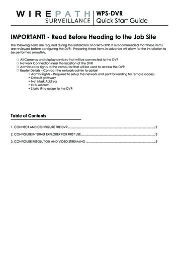
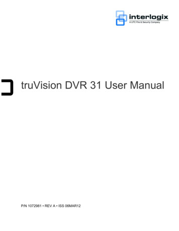
Chapter 3: Operating instructionsIconNameFunctionPTZLaunches PTZ mode.PlayPlays back video instantly starting at one minute from thecurrent date and time.EscHides the function commands.Using the IR remote controlThe IR remote control buttons are similar to those on the DVR 31 front panel.You can use the remote control to perform any DVR 31 function.Figure 5: IR remote MENU7DVR IDCamera123456789101112131415165truVision DVR 31 User Manual15
Chapter 3: Operating instructionsTable 6: IR remote control descriptionsItemNameDescription1Function buttonsChange the DVR 31 operating mode. For example, press PTZ to gointo PTZ mode. See “Operating modes” on page 17 for moreinformation.2DirectionalIn menu mode, navigate and select commands. In PTZ mode, usecontrols and Enter for PTZ controls.buttonWhile in a setup menu, use the Left or Right Arrow keys to navigatethrough fields. Use the Up or Down Arrow keys to change the valueof a selected field.3EscExit a screen or cancel a selection.4DVR IDSwitch control between different DVR 31 units.5Numeric buttonsIn live mode, display the corresponding camera. In edit mode, enternumeric characters.6MenuDisplay the main menu.7PlaybackControl video playback speed.To place batteries into the IR remote control:1. Remove the battery cover.2. Insert the batteries (AAA). Make sure that the positive and negative poles arecorrectly placed.3. Replace the battery cover.To connect the remote control to the DVR 31:1. Turn on the DVR 31 and wait for live video to appear.2. On the remote control, press the DVR ID button, and then press the 1 button.Note: The numeric button depends on the remote ID assigned to the DVR 31.The remote ID assigned is 1 by default. See “Controlling multiple DVRs withone remote control” below for more information.3. The remote control is now operational.Controlling multiple DVRs with one remote controlYou can control up to 16 DVRs with one remote control. Each DVR must have aunique remote ID assigned. To connect the remote control to a DVR, press theDVR ID button on the remote control, and then press the numeric button with thedesired remote ID. For more information on assigning a remote ID to a DVR, see“Audio and remote” on page 80.16truVision DVR 31 User Manual
Chapter 3: Operating instructionsOperating modesTable 7 below describes the various operating modes for the DVR 31.Table 7: DVR 31 operating modesModeDescriptionLiveDisplays live video from a specific camera.SequenceDisplays live video in a programmed sequence of cameras.MenuDisplays menu options for configuration.PTZDisplays live video from multiple cameras in a programmed sequence.PlaybackPlays back recorded video.FreezeFreezes live or playback video.SpotOn-screen display for spot monitor.Main menu overviewThe built-in interface of the DVR 31 includes a main menu screen with eightcommand buttons. Each command displays a dialog screen that lets you edit agroup of DVR 31 settings. The main menu screen is shown in Figure 6 on page18. Access to different option screens varies depending on your accessprivileges. Most screens are available only to system administrators. The menuicon is highlighted when selected.truVision DVR 31 User Manual17
Chapter 3: Operating instructionsFigure 6: Main menuMain menu commandsTable 8 below describes the commands available for each menu items.Table 8: Main menu commandsCommandDescriptionCamerasConfigures camera settings including motion detection, PTZ, videoimage adjustments, camera title, covert camera, audio off, and copysettings to other cameras.ScheduleConfigures recording and schedule settings including recording quality,and schedule definitions.AlarmsConfigures alarm settings including alarm input, relay output, video lossdetection, remote alert, prealarm, and post-alarm seconds.UsersConfigures users, passwords, access privileges, and defines privilegelevels.NetworkConfigures standard network settings including IP address, e-mailnotifications, DDNS setup, and advanced network settings.DisplayConfigures display settings including sequence order, resolution, dwelltime, on-screen alerts, display formats, and transaction overlay.18truVision DVR 31 User Manual
Chapter 3: Operating instructionsCommandDescriptionSystemConfigures system settings including system date and time, audiooutput, device name, RS-485 settings, RS-232 settings, firmwareupgrade, hard drive settings, system log, and shutdown.InfoDisplays the unit’s system information including model ID, networkaddress, firmware version, and MAC addresses.Back Arrow iconExits Main menuUsing the main menuUse the mouse or directional arrow keys to navigate through the menucommands and display the configuration screens. To display the main menu,click the Menu button on the mouse toolbar or press the Menu button on the frontpanel or remote control.Navigating through dialog screensEach dialog screen includes various options and buttons as seen in Figure 7 onpage 20. The frame surrounding an option or button indicates that this option (orbutton) is currently selected.Use the mouse to select any option or button on the screen. You can also usethe directional arrow buttons (Up, Down, Left, or Right) to navigate through theoptions. Changes to screen settings can be entered in various ways as shown inTable 9 on page 20.Saving your changesClosing a screen, either by clicking the X button at the top right corner or by rightclicking, automatically saves and applies your changes. You cannot cancel orundo any changes you have entered in a dialog screen.truVision DVR 31 User Manual19
Chapter 3: Operating instructionsFigure 7: Cameras menuTable 9: Field entry typesTypeDescriptionList boxProvides more than two values for the option. Only one of them canbe selected. Click the scroll arrows at the right-hand side of the boxto scroll through the possible values. You can also use the Up orDown Arrow buttons to select a value.Edit boxLets you to enter characters into the settings, such as cameraname. Enter characters into an edit box through the virtualkeyboard. See “Using the virtual keyboard” below for moreinformation.ButtonTriggers a special function or allows you to display a new screen.For example, click the Setup button to display the setup screen.Using the virtual keyboardThe virtual keyboard allows you to enter a full range of alphanumeric characters,such as camera name, through a virtual keyboard as shown in Figure 8 on page21. The virtual keyboard automatically displays when entering values in an edit20truVision DVR 31 User Manual
Chapter 3: Operating instructionsbox field. You can use the front panel, IR remote control, or USB mouse to entercharacters with the virtual keyboard.Figure 8: Virtual keyboardTo enter characters in an edit box:1. Highlight the edit box.2. Click the mouse within the action frame (or press Enter in the front panel orremote control) to display the virtual keyboard.3. Select the characters required.4. When finished, click OK on the virtual keyboard to close the keyboard.Exiting the main menuClick Esc on the mouse toolbar (or right-click) or press Esc on the front panel orremote control to exit the main menu and return to live mode.truVision DVR 31 User Manual21
Chapter 3: Operating instructions22truVision DVR 31 User Manual
Chapter 4Basic operationSummaryThis chapter describes the basic operation of the DVR 31 such as how to turn onthe unit, log on, control a PTZ camera, play back video, and archive recordedvideo files.ContentTurning on the DVR 31 24Live mode 24Right-click mouse menu 25Viewing in full screen 25Viewing in multiscreen 26Spot monitor 26Controlling the spot monitor 26Logging on 27Logging off 28Controlling a PTZ camera 28Accessing PTZ mode 28PTZ control buttons 29Calling up a preset PTZ point 30Exiting the PTZ control mode 30Playing back video 30Instant video playback 31Searching video for playback 31Playback controls 35Exiting playback mode 36Archiving recorded files 36Using Quick Archive in live mode 37Using the Archive screen in live mode 37Archiving a video segment in playback mode 39Using the DVR player 39Turning off the DVR 31 41truVision DVR 31 User Manual23
Chapter 4: Basic operationTurning on the DVR 31Before turning the DVR 31 power on, connect at least one monitor to the mainvideo out or the VGA interface. Otherwise, you will not be able to see the userinterface and operate the device. Use the power switch on the back panel to turnon the unit.Live modeThe DVR 31 automatically enters into live mode once powered on. Live moderefers to the mode in which the DVR 31 displays live video from cameras. TheDVR 31 on-screen display presents information such as the camera title, thecurrent operating mode, and the date and time information as shown in Figure 9below.Figure 9: On screen display1.Camera title2.Mouse toolbar24truVision DVR 31 User Manual
Chapter 4: Basic operationNote: To move the camera title to a different position, left-click the mouse on thedate/time, and then select a new position while in live mode.Right-click mouse menuRight-click with the mouse to display the right-click mouse menu.Figure 10: Right-click mouse menuThe follow options are available: apeHide PanelViewing in full screenPress a numeric button to switch to the corresponding camera display. Forexample, press 2 to view camera 2.truVision DVR 31 User Manual25
Chapter 4: Basic operationViewing in multiscreenUse the Display button on the front panel to cycle through different displayformats. Figure 11 below displays the multiscreen formats available as defaults.Figure 11: Display Spot monitorTo connect the spot monitor:1. Connect the spot monitor to the Spot video out port on the back panel using acomposite cable.2. While in live mode, press and hold a numeric key for two seconds on the frontpanel or remote control.3. The spot monitor displays the corresponding camera in full screen.The spot monitor only supports full screen mode.Note: Make sure that there is video signal input. Otherwise the spot monitor willonly show a blank screen.Controlling the spot monitorPress and hold a numeric button for two seconds to display the correspondingcamera in full screen. Additionally, press and hold the SEQ button (on the front26truVision DVR 31 User Manual
Chapter 4: Basic operationpanel or remote control) to initiate sequence mode on the spot monitor.Alternatively, click the Monitor button on the mouse toolbar to toggle to the spotmonitor function, and then click the Sequence button to begin sequence, asshown in Figure 12 below.Figure 12: Spot monitor functionLogging onThe DVR 31 is shipped with a predefined user for the system administrator. Thedefault system administrator logon uses “admin” as a user name with a passwordof 1234. You can modify the admin password but not the admin user name. UTCFire & Security recommends that you change the admin password once youhave completed the installation and setup to
The DVR 31's pentaplex operation enables users to view live video, search and play back any recorded video by date and time or by event, and back up the configuration and video data, without interrupting the ongoing DVR recording process. In addition to the new H.264 compression mode, the DVR's graphical user