Transcription
Digital Video RecorderQuick Operation Guide
Quick Operation Guide of Digital Video RecorderTABLE OF CONTENTSDVR Pre-Installation . 5DVR Installation . 5Hard Disk Installation . 5Front Panels. 7Rear Panels . 8Peripheral Connections . 9Wiring of Alarm Input . 9Wiring of Alarm Output . 9Alarm Connection . 9RS-485 and Controller Connection . 10Specifications . 11Table 1 Specification . 11HDD Storage Calculation Chart . 13Accessing by Web Browser . 14Logging In. 14Live View . 14Recording . 15Playback . 16Log . 17Menu Operation . 18Menu Structure. 18Startup and Shutdown . 18Live View . 19Adding IP Cameras . 19Record . 21Instant Recording . 21All-day Recording . 21Playback . 22Backup . 231
Quick Operation Guide of Digital Video RecorderRegulatory informationFCC informationFCC compliance: This equipment has been tested and found to comply with the limits for a digital device, pursuantto part 15 of the FCC Rules. These limits are designed to provide reasonable protection against harmfulinterference when the equipment is operated in a commercial environment. This equipment generates, uses, andcan radiate radio frequency energy and, if not installed and used in accordance with the instruction manual, maycause harmful interference to radio communications. Operation of this equipment in a residential area is likely tocause harmful interference in which case the user will be required to correct the interference at his own expense.FCC conditionsThis device complies with part 15 of the FCC Rules. Operation is subject to the following two conditions:1. This device may not cause harmful interference.2. This device must accept any interference received, including interference that may cause undesired operation.EU Conformity StatementThis product and - if applicable - the supplied accessories too are marked with "CE" and comply therefore with theapplicable harmonized European standards listed under the Low Voltage Directive 2006/95/EC, the EMCDirective 2004/108/EC, the RoHS Directive 2011/65/EU.2012/19/EU (WEEE directive): Products marked with this symbol cannot be disposed of as unsorted municipalwaste in the European Union. For proper recycling, return this product to your local supplier upon the purchase ofequivalent new equipment, or dispose of it at designated collection points. For more information see:www.recyclethis.info.2006/66/EC (battery directive): This product contains a battery that cannot be disposed of as unsorted municipalwaste in the European Union. See the product documentation for specific battery information. The battery ismarked with this symbol, which may include lettering to indicate cadmium (Cd), lead (Pb), or mercury (Hg). Forproper recycling, return the battery to your supplier or to a designated collection point. For more information see:www.recyclethis.info.2
Quick Operation Guide of Digital Video RecorderTrademarks and Registered Trademarks Windows and Windows mark are trademarks or registered trademarks of Microsoft Corporation in the UnitedStates and/or other countries. HDMI, HDMI mark and High-Definition Multimedia Interface are trademarks or registered trademarks ofHDMI Licensing LLC. The products contained in this manual are authorized by HDMI Licensing LLC with the use right of the HDMItechnology. VGA is the trademark of IBM. UPnPTM is a certification mark of the UPnPTM Implementers Corporation. Other names of companies and product contained in this manual may be trademarks or registered trademarksof their respective owners.3
Quick Operation Guide of Digital Video RecorderThank you for purchasing our product. If there is any question or request, please do not hesitate to contact dealer.This manual is applicable to 720P Turbo HD DVR4
Quick Operation Guide of Digital Video RecorderDVR Pre-InstallationThe HD-TVI series DVR is highly advanced surveillance equipment that should be installed carefully. Please takeinto consideration the following precautionary steps before installation of the DVR.1. Keep all liquids away from the DVR.2. Install the DVR in a well-ventilated and dust-free area.3. Ensure environmental conditions meet factory specifications.4. Install a manufacturer recommended HDD.DVR InstallationDuring the installation of the DVR:1.2.3.4.5.6.7.8.Use brackets for rack mounting.Ensure there is ample room for audio and video cables.When installing cables, ensure that the bend radius of the cables are no less than five times than its diameter.Connect both the alarm and RS-485 cable.Allow at least 2cm ( 0.75-inch) of space between racks mounted devices.Ensure the DVR is grounded.Environmental temperature should be within the range of -10 ºC 55 ºC, 14ºF 131ºF.Environmental humidity should be within the range of 10% 90%.Hard Disk InstallationBefore you start:Before installing a hard disk drive (HDD), please make sure the power is disconnected from the DVR. A factoryrecommended HDD should be used for this installation.Up to 2 SATA hard disks can be installed on your DVR.Tools Required: Screwdriver.As the installation steps of HDD are similar among different models, here we take one model as an example.Steps:1. Remove the cover from the DVR by unfastening the screws on the back and side.2. Connect one end of the data cable to the motherboard of DVR and the other end to the HDD.5
Quick Operation Guide of Digital Video Recorder3. Connect the power cable to the HDD.4. Place the HDD on the bottom of the device and then fasten the screws on the bottom to fix the HDD.5. Re-install the cover of the DVR and fasten screws.6
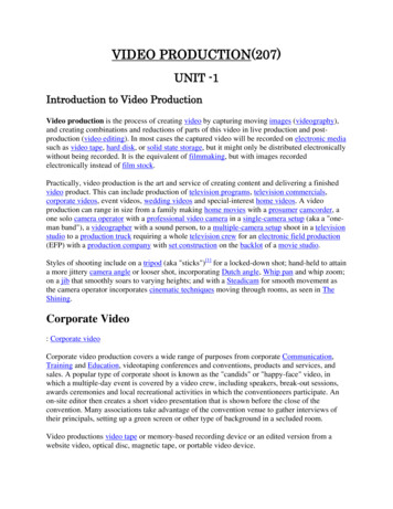
Quick Operation Guide of Digital Video RecorderFront PanelsFront Panel of 4/8/16ch DVRDescription of Front PanelNo.1NameFunction DescriptionPOWERPOWER indicator turns green when DVR is powered up.STATUSSTATUS indicator lights in red when data is being read from or written to HDD.Tx/RxTx/Rx indictor blinks green when network connection is functioning properly.The DIRECTION buttons are used to navigate between different fields and itemsin menus.In the Playback mode, the Up and Down button is used to speed up and slowDIRECTIONdown recorded video. The Left and Right button will select the next and previousrecord files.In Live View mode, these buttons can be used to cycle through channels.2In PTZ control mode, it can control the movement of the PTZ camera.The ENTER button is used to confirm selection in any of the menu modes.It can also be used to tick checkbox fields.ENTERIn Playback mode, it can be used to play or pause the video.In single-frame Playback mode, pressing the button will advance the video by asingle frame.3MENU4ESC5IR Receiver6USB InterfaceAccess the main menu interface.Exit and back to the previous menu.Receiver for IR remote.Connects USB mouse or USB flash memory devices.7
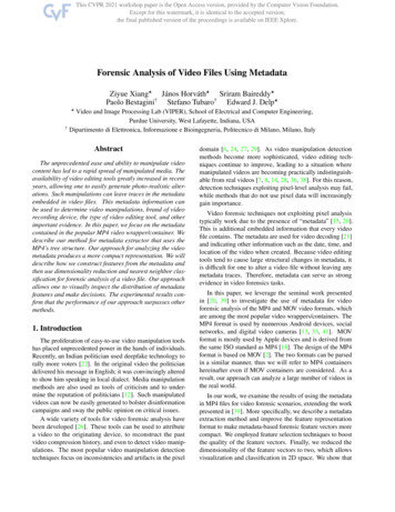
Quick Operation Guide of Digital Video RecorderRear PanelsThe rear panel vaires according to different models.Rear panel of 4ch/8ch/16ch DVRDescription of Rear PanelNo.ItemDescription12VIDEO INAUDIO INBNC interface for TVI and analog video input.RCA connector34AUDIO OUTVGARCA connectorDB15 connector for VGA output. Display local video output and menu.56HDMIUSB PortHDMI video output connector.Universal Serial Bus (USB) port for additional devices.78Network InterfaceRS-485 InterfaceConnector for networkConnector for RS-485 devices.910Power SupplyPower SwitchDC 12V power supply.Switch for turning on/off the device.11GNDGround8
Quick Operation Guide of Digital Video RecorderPeripheral ConnectionsWiring of Alarm InputThe alarm input is an open/closed relay. To connect the alarm input to the device, use the following diagram.If the alarm input is not an open/close relay, please connect an external relay between the alarm input and thedevice.Wiring of Alarm OutputTo connect to an alarm output (AC or DC load), use the following diagram:DC Load Connection DiagramAC Load Connection DiagramFor DC load, the jumpers can be used within the limit of 12V/1A safely.To connect an AC load, jumpers should be left open (you must remove the jumper on the motherboard in theDVR). Use an external relay for safety (as shown in the figure above).There are 4 jumpers (JP1, JP2, JP3, and JP4) on the motherboard, each corresponding with one alarm output. Bydefault, jumpers are connected. To connect an AC load, jumpers should be removed.Example:If you connect an AC load to the alarm output 3 of the DVR, then you must remove the JP 3.Alarm ConnectionTo connect alarm devices to the DVR:1. Disconnect pluggable block from the ALARM IN /ALARM OUT terminal block.2. Press and hold the orange part of the pluggable block; insert signal cables into slots and release the orange part.Ensure signal cables are in tight.9
Quick Operation Guide of Digital Video Recorder3. Connect pluggable block back into terminal block.RS-485 and Controller ConnectionFor 4ch/8ch/16ch DVRTo connect PTZ to the DVR:1. Disconnect pluggable block from the RS-485 terminal block.2. Press and hold the orange part of the pluggable block; insert signal cables into slots and release the orangepart. Ensure signal cables are in tight.3. Connect A on PTZ to D on terminal block and B- on controller to D- on terminal block. Fasten stopscrews.4. Connect pluggable block back into terminal block.Make sure both the controller and DVR are grounded.10
Quick Operation Guide of Digital Video RecorderSpecificationsTable 1 SpecificationModel4chVideo compressionH.2648ch16ch8-ch16-chAnalog and HD-TVI video4-chinputBNC interface (1.0Vp-p, 75 Ω)Supported camera types720P/25, 720P/30, 720P/50, 720P/60, 1080P/25, 1080P/30, CVBSVideo/Audioinput1-ch2-ch2-chIP video inputUp to 2.0MP resolutionAudio compressionAudio input / Two-way audioinHDMI / VGA outputG.711u1-ch, RCA (2.0 Vp-p, 1 KΩ)1920 1080 / 60 Hz,1280 1024 / 60 Hz, 1280 720 / 60 Hz, 1024 768 / 60 HzMain stream: 1080P(non-real-time) / 720P / VGA / WD1 / 4CIF / CIFEncoding resolutionSub-stream: WD1(non-real-time) / 4CIF(non-real-time) / CIF / QCIF /QVGAMain stream: 1/16 fps Real time frame rateFrame rateSub-stream: 1/16 fps Real time frame rateVideo/AudiooutputVideo bitrate32 Kbps-6 MbpsAudio output1-ch, RCA (Linear, 1KΩ)Audio bitrate64 KbpsDual-streamSupportStream typeVideo, Video & AudioSynchronous playback4-chPlayback resolution1080P / 720P / VGA / WD1 / 4CIF / CIF / QVGA / QCIFRemote connections1288-ch16-chNetworkmanagementNetwork protocolsTCP/IP, PPPoE, DHCP, DNS, DDNS, NTP, SADP, SMTP, SNMP, NFS,iSCSI, UPnP , HTTPSSATA1 SATA interface2 SATA interfacesCapacityUp to 4 TB capacity for each diskHard disk1; 10M / 100M /Network interfaceinterfaceExternalinterface1; standard RS-485 serial interface, half-duplexUSB port2 USB2.0Power supply12V DC(without hard disks) 15W 20WWorking temperature-10 ºC 55 ºC (14 ºF 131 ºF)Working humidity10% 90%Chassis1U chassisself-adaptive 30W380mm 1U chassis380 290 48mmDimensions(W D H)1000MEthernet interfaceSerial interfaceConsumptionGeneral1; 10M / 100M self-adaptive Ethernet315 242 45mm (12.4 9.5 1.8 inch)(15.0 11.4 1.9inch)11
Quick Operation Guide of Digital Video RecorderWeight(without hard disks) 1.5Kg (3.3lb)12 2Kg (4.4lb)
Quick Operation Guide of Digital Video RecorderHDD Storage Calculation ChartThe following chart shows an estimation of storage space used based on recording at one channel for an hour at afixed bit rate.Bit age M450M562M675M787M900M1800M3600M7200MPlease note that supplied values for storage space used are just for reference. Storage space used is estimated byformulas and may have some deviation from actual value.13
Quick Operation Guide of Digital Video RecorderAccessing by Web BrowserLogging InYou can get access to the device via web browser. Open web browser, input the IP address of the device and thenpress Enter. The login interface appears.Input the user name and password, and click the Login button. You may use one of the following listed web browsers: Internet Explorer 6.0, Internet Explorer 7.0, InternetExplorer 8.0, Internet Explorer 9.0, Internet Explorer 10.0, Apple Safari, Mozilla Firefox, and GoogleChrome. The supported resolutions include 1024*768 and above. The default IP address is 192.0.0.64. The default user name is admin, and password is 12345. You are highly recommended to change the default password right after the first login to avoid safetyproblem.When you log in for the first time, the system will remind you to install the Plug-in control. After the installation,you can configure and manage the device remotely.Live ViewThe live view interface appears by default when you log in the device.Interface IntroductionNo.NameDescription1Channel ListDisplays the list of channels and the playing and recording status of each14
Quick Operation Guide of Digital Video RecorderNo.NameDescriptionchannel.2Live View WindowDisplays the image of channel, and multi-window division is supported.3Play Control BarPlay control operations are supported.Pan, tilt, zoom operations are supported, as well as preset editing and calling.PTZ Control4PTZ function can only be realized if the connected camera supports PTZ control.Video Parameters5ConfigurationBrightness, contrast, saturation and hue of the image can be edited.Start Live ViewSteps:1. In the live view window, select a playing window by clicking the mouse.2. Double click a camera from the device list to start the live view.3. You can click thebutton on the toolbar to start the live view of all cameras on the device list.Refer to the following table for the description of buttons on the live view window:Icon/DescriptionIconDescriptionSelect the window-division modePrevious pageStart/Stop all live viewNext pageCapture pictures in the live view/mode/Start/Stop all recording/Enable/Disable digital zoom/Open/Close audioStart/Stop two-way AudioAdjust volumeRecordingBefore you startMake sure the device is connected with HDD or network disk, and the HDD or network disk has been initializedfor the first time to use.Two recording types can be configured: Manual and Scheduled. The following section introduces theconfiguration of scheduled recording.Steps:1. Click Remote Configuration Camera Settings Record Schedule to enter Record Schedule settingsinterface.2. Select the camera to configure the record schedule.3. Check the checkbox of Enable Record Schedule to enable recording schedule.4. Click Edit to edit record schedule.5. Choose the day in a week to configure scheduled recording.15
Quick Operation Guide of Digital Video Recorder1) Configure All Day or Customize Record: If you want to configure the all-day recording, please check the All Day checkbox. If you want to record in different time sections, check the Customize checkbox. Set the Start Timeand End Time.The time of each segment cannot be overlapped. Up to 8 segments can be configured.2) Select a Record Type. The record type can be Continuous, Motion, Alarm, Motion & Alarm, andMotion Alarm.3) Check the checkbox of Select All and click Copy to copy settings of this day to the whole week. Youcan also check any of the checkboxes before the date and click Copy.4) Click OK to save the settings and exit the Edit Schedule interface.6. Click Advanced to configure advanced record parameters.7. Click Save to validate the above settings.PlaybackInterface IntroductionNo.NameDescription1Channel ListDisplays the list of channels and the playing status of each channel.2Playback WindowDisplays the image of channel.3Play Control Bar:Play control operations are supported.4Time LineDisplays the time bar and the records marked with different colors.5Playback StatusDisplays the playback status, including channel number and playback speed.6CalendarYou can select the date to play.Start PlaybackSteps:16
Quick Operation Guide of Digital Video Recorder1. Click Playback on the menu bar to enter playback interface.2. Click the camera from the device list for playback.3. Select the date from the calendar and click Search.4. Click the Play button to play the video file searched on the current date.5. Use the buttons on the toolbar to operate in playback eStopSlow downSpeed upPlay by single frameCaptureStop all playbackDownloadVideo clip/Full ScreenOpen/Close audioReverse play6. You can drag the progress bar with the mouse to locate the exact playback point. You can also input the timein the textboxand clickbutton to locate the playback point.The color of the video on the progress bar stands for the different video types.LogYou can view and export the log files at any time, including operation, alarm, exception and information of device.Before you startThe Log function can be realized only when the device is connected with HDD or network disk. And make surethe HDD or network disk has been initialized for the first time to use.Steps:1. Click Log on the menu bar to enter the Log interface.2. Set the log search conditions to refine your search, including the Major Type, Minor Type, Start Time andEnd Time.3. Click the Search button to start searching log files.4. The matched log files will be displayed on the list shown below.Up to 100 log files can be displayed on each page.You can click thebutton to save the searched log files to local directory.17
Quick Operation Guide of Digital Video RecorderMenu OperationMenu cheduleOSDGeneralSystem InfoLogoutEventManual ownAdvancedPTZLive adePrivacyMaskUserDefaultVideoTamperingNet DetectVideo LossHDD DetectVQDStartup and ShutdownProper startup and shutdown procedures are crucial to expand the service time of the DVR.To start the DVR:Check the power supply is plugged into an electrical outlet. It is HIGHLY recommended that an UninterruptiblePower Supply (UPS) be used in conjunction with the device. Turn on the power switch on the rear panel; thePower indicator LED on the front panel should be yellow.To shut down the DVR:Steps:1. Enter the Shutdown menu.Menu Shutdown2. Select the Shutdown button.3. Click the Yes button.4. Turn off the power switch on the rear panel when the note appears.18
Quick Operation Guide of Digital Video RecorderAfter the device starting up, the wizard will guide you through the basic settings, including edting password, dateand time settings, network settings, HDD initializing, and recording.Live ViewSome icons are provided on screen in Live View mode to indicate different camera status. These icons include:Live View IconsIn the live view mode, there are icons at the right top of the screen for each channel, showing the status of therecord and alarm in the channel, so that you can find problems as soon as possible.Indicating that there is an alarm or are alarms. Alarm includes video loss, tampering, motion detection orsensor alarm, etc.Recording (manual record, continuous record, motion detection or alarm triggered record)Alarm & RecordingEvent/Exception (event and exception information, appears at the lower-left corner of the screen.)Adding IP CamerasThe connection of IP cameras is supported by the HDVR only.For the 4ch models, 1 network camera can be added, and for other HDVR models, 2 network cameras can beadded.Steps:1.Right-click the mouse in the live view mode to show the right-click menu.19
Quick Operation Guide of Digital Video Recorder2.Select Add IP Camera in the pop-up menu to enter the IP Camera Management interface.3.The online cameras with same network segment will be displayed in the camera list. Click theadd the camera.button toThe added camera is marked in white while the camera not added is marked in yellow.Explanation of the iconsIconExplanationIconEdit basic parameters of the cameraExplanationAdd the detected IP camera.The camera is disconnected; you can clickThe camera is connected.the icon to get the exception information ofcamera.Delete the IP camera.4.Advanced settings of the camera.To add other IP cameras:1)Click the Custom Adding button to pop up the Add IP Camera (Custom) interface.20
Quick Operation Guide of Digital Video Recorder2)You can edit the IP address, protocol, management port, and other information of the IP camera to beadded.3)Click Add to add the camera.4)(For the encoders with multiple channels only) check the checkbox of Channel No. in the pop-up window,as shown in the following figure, and click OK to finish adding.RecordBefore you start:Make sure that the HDD has already been installed. If not, please install a HDD and initialize it. You may refer tothe user manual for detailed information.Purpose:Two kinds of record types are introduced in the following section, including Instant Record and All-day Record.And for other record types, you may refer to the user manual for detailed information.After rebooting all the manual records enabled are canceled.Instant RecordingOn the live view window of each channel, there is a quick setting toolbar which shows on the bottom of thewindow when you click on it.Click theicon to enable the record, and the icon turns tothen the icon turns to. And clickicon to disable the record,.All-day RecordingPerform the following steps to set the all-day recording.On the live view window, right lick the window and move the cursor to the Start Recording option, and selectContinuous Record or Motion Detection Record on your demand.And click the Yes button in the popup Attention message box to confirm the settings. Then all the channels willstart to record in the selected mode.21
Quick Operation Guide of Digital Video RecorderPlaybackPlay back the record files of a specific channel in the live view menu. OPTION 1:Choose a channel under live view using the mouse and click thebutton in the shortcut operation menu.Only record files recorded during the last five minutes on this channel will be played back. OPTION 2:1. Enter the Playback menu.Right click a channel in live view mode and select Playback from the menu.2. Playback management.The toolbar in the bottom part of Playback interface can be used to control playing process.Just check the channel or channels if you want to switch playback to another channel or execute simultaneousplayback of multiple channels.22
Quick Operation Guide of Digital Video RecorderBackupRecorded files can be backed up to various devices, such as USB flash drives, USB HDDs or USB DVD writers.To export recorded files:1. Enter Video Export interface.Choose the channel(s) you want to back up and click the Quick Export button.2. Enter Export interface, choose backup device and click the Export button to start exporting.3. Check backup result.Choose the record file in Export interface and click23button to check it.
into consideration the following precautionary steps before installation of the DVR. 1. Keep all liquids away from the DVR. 2. Install the DVR in a well-ventilated and dust-free area. 3. Ensure environmental conditions meet factory specifications. 4. Install a manufacturer recommended HDD. DVR Installation