Transcription
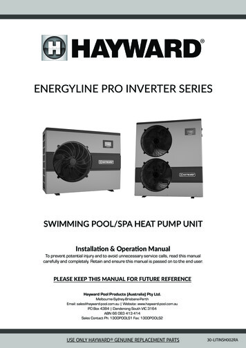
ENERGYLINE PRO INVERTER SERIESSWIMMING POOL/SPA HEAT PUMP UNITInstallation & Operation ManualTo prevent potential injury and to avoid unnecessary service calls, read this manualcarefully and completely. Retain and ensure this manual is passed on to the end user.PLEASE KEEP THIS MANUAL FOR FUTURE REFERENCEHayward Pool Products (Australia) Pty Ltd.Melbourne-Sydney-Brisbane-PerthEmail: sales@hayward-pool.com.au Website: www.hayward-pool.com.auPO Box 4384 Dandenong South VIC 3164ABN 66 083 413 414Sales Contact Ph: 1300POOLS1 Fax: 1300POOLS2USE ONLY HAYWARD GENUINE REPLACEMENT PARTS30-LITINSH002RA
IMPORTANT SAFETY INSTRUCTIONSBefore installing or servicing this electrical equipment, turn OFF and ISOLATE power supply.WARNINGRead and follow all instructions in this owner’s manual and onthe equipment. Failure to follow instructions can cause severeinjury and/or deathWARNING – This manual contains important information about the installation, operation, and safe use of this heatpump that must be transferred through to the end user of this product.WARNING – This product should be installed and serviced ONLY by a qualified professional.WARNING – All electrical wiring MUST be performed by a qualified electrical contractor, and must conform to Local/State/Federal Government electrical regulations and the Latest Edition AS/NZS 3000 Wiring Rules.WARNING – This appliance is not intended for use by persons (including children) with reduced physical, sensory ormental capabilities, or lack of experience and knowledge, unless they have been given supervision or instruction concerninguse of the appliance by a person responsible for their safety. CHILDREN SHOULD BE SUPERVISED TO ENSURE THAT THEYDO NOT PLAY WITH THE APPLIANCE.CAUTION – This heater is intended for use on permanently installed swimming pools and may also be used with hottubs and spas if so marked. Do NOT use with storable pools. A permanently installed pool is constructed in or on the groundor in a building such that it cannot be readily disassembled for storage. A storable pool is constructed so that it is capable ofbeing readily disassembled for storage and reassembled to its original integrity. Though this product is designed for outdooruse, it is strongly advised to protect the electrical components from the weather. Select a well-drained area, one that will notflood when it rains. It requires free circulation of air for proper operation. Do not install in a damp or non-ventilated location.WARNING – Pool and spa components have a finite life. All components should be inspected frequently and replacedat least every ten years, or if found to be damaged, broken, cracked, missing, or not securely attached.WARNING – Risk of Electric Shock. All electrical wiring must be performed by a qualifiedelectrical contractor, and must conform to Local/State/Federal electrical regulations and the LatestEdition AS/NZ 3000 Wiring Rules. All electrical circuits must be supplied through a Residual CurrentDevice - RCD (Safety Switch), with a residual operating current not exceeding 30 mA. Hazardousvoltage can shock, burn and cause death or serious property damage.WARNING – The power supply to the heat pump must be supplied through an isolator switch located next to theunit and complying with the Latest Edition of the AS/NZS 3000 Wiring Rules.WARNING – Hayward recommends that a Lightning Surge Protector Device (SPD) is installed on the feed circuit tothe heat pump by a qualified electrical contractor in accordance with AS/NZS 3000 Australian Wiring Rules Latest Edition.WARNING – To reduce the risk of electric shock replace damaged wiring immediately. Locate the power cord so thatit cannot be damaged by lawn mowers, hedge trimmers and other equipment.WARNING – Never operate the circulation system at more than 344 kPa (50 PSI) maximum.Page 2USE ONLY HAYWARD GENUINE REPLACEMENT PARTS
IMPORTANT SAFETY INSTRUCTIONSBefore installing or servicing this electrical equipment, turn OFF and ISOLATE power supply.WARNING – Hazardous Pressure. Pool and spa water circulation systems operate under hazardous pressure duringstart-up, normal operation, and after pump shut-off. Stand clear of circulation system equipment duringpump start-up. Failure to follow safety and operation instructions could result in violent separation of thepump housing and cover due to pressure in the system. This separation could cause property damage,severe personal injury, or death. Before servicing the pool and spa water circulation system, all systemand pump controls must be in the off position and the Filter Manual Air Relief Valve must be in the openposition. Before starting the system pump, all valves must be set in a position to allow system waterto return back to the pool. Do not change the Filter Control Valve position while the system pump isrunning. Before starting the system pump, fully open the Filter Manual Air Relief Valve. Do not close theFilter Manual Air Relief valve until all the air is expelled and a steady stream of water is discharged fromthe valve. All suction and discharge valves MUST BE OPEN when starting the circulation system. Failureto do so could result in severe personal injury and/or property damage.WARNING – Separation Hazard. Failure to follow safety and operation instructions could result in violent separationof pump components. Strainer cover must be properly secured to pump housing with the strainercover lock ring. Before servicing pool and spa circulation system, all system and pump controls mustbe in off position and the Filter Manual Air Relief Valve must be in open position. Do not operate pooland spa circulation system if system components are not assembled properly, damaged, or missing.Do not operate pool and spa circulation system unless the Filter Air Relief Valve body is in lockedposition within the filter upper body. All suction and discharge valves MUST BE OPEN when starting thecirculation system. Failure to do so could result in severe personal injury and/or property damage.WARNING – Suction Entrapment Hazard. The force from suction in suction outlets and/or suction outlet covers whichare damaged, broken, cracked, missing, or unsecured, can cause severe injury and/or death due to thefollowing entrapment hazards:Hair Entrapment - Hair can become entangled in suction outlet cover.Limb Entrapment - A limb inserted into an opening of a suction outlet sump or suction outlet coverthat is damaged, broken, cracked, missing, or not securely attached, can result in a mechanical bind orswelling of the limb.Body Suction Entrapment - A differential pressure applied to a large portion of the body or limbs canresult in an entrapment.Evisceration/Disembowelment - A negative pressure applied directly to the intestines through anunprotected suction outlet sump or suction outlet cover which is damaged, broken, cracked, missing, orunsecured, can result in evisceration/disembowelment.Mechanical Entrapment - There is potential for jewelry, swimsuits, hair decorations, fingers, toes, orknuckles, to be caught in an opening of a suction outlet cover resulting in mechanical entrapment.WARNING – To Reduce the risk of Entrapment Hazards:»» When outlets are small enough to be blocked by a person, a minimum of two functioning suctionoutlets per pump must be installed. Suction outlets in the same plane (i.e. floor or wall), must beinstalled a minimum of 0.91 metres or three feet (3’) apart, as measured from near point to nearpoint to avoid dual blockage by a user.»» Dual suction fittings shall not be located on seating areas or on the backrest for such seating areas.»» Never use pool or spa if any suction outlet component is damaged, broken, cracked, missing, or notsecurely attached.»» Replace damaged, broken, cracked, missing, or not securely attached suction outlet components immediately.»» In addition to installing two or more suction outlets per pump, follow all national, state and local governmentregulations as well as AS 1926.3 Latest Edition.»» Installation of a vacuum release or vent system, which relieves entrapping suction, is recommended.USE ONLY HAYWARD GENUINE REPLACEMENT PARTSPage 3
CONTENTS1. INTRODUCTION1.1 Preface1.2 Spa Use Safety Guidelines2. SPECIFICATIONS2.1 Technical data for the swimming pool heat pump unit2.2 Operating Range2.3 Dimensions3. INSTALLATION AND CONNECTION3.13.23.33.43.53.6Functional DiagramHeat Pump UnitHydraulic ConnectionElectrical ConnectionInitial Start-upWater Flow Setting4. USER INTERFACE4.14.24.34.44.54.6General PresentationSetting and Visualisation of the Set PointSetting the Date and TimeTimer Function SettingsLocking and Unlocking the Touch ScreenSILENT Function Settings5. MAINTENANCE AND WINTERISING5.1 Maintenance5.2 Winterising6. TECHNICAL DRAWINGS6.16.26.36.46.5Electrical DiagramsHeating Priority Wiring for a Monophasic PumpHeating Priority Wiring for a Three Phase PumpWiring the Heat Pump to a Control UnitExploded View and Spare Parts7. TROUBLESHOOTING7.1 Error Codes7.2 Recording Base7.3 WarrantyPage 4USE ONLY HAYWARD GENUINE REPLACEMENT 6272840404242
1. INTRODUCTION1.1 PrefaceWe thank you for purchasing this Hayward swimming pool heat pump unit. The Energyline Pro INVERTER was designed according to strictmanufacturing standards to meet the highest quality requirements. The Energyline Pro INVERTER will offer you exceptional performancethroughout the swimming season by adapting its power, electricity consumption and sound level to your swimming pool's heating needs withits INVERTER control logic.This manual includes all of the necessary information concerning installation, debugging and maintenance. Please attentively read thismanual before opening the unit or before carrying out any maintenance operations on it. The manufacturer of this product will not,under any circumstances, be held responsible in the case of injury to the user or damage to the unit resulting from improper installation,debugging or unnecessary maintenance. It is essential to follow all of the instructions specified in the manual at all times.»» The unit must only be installed by a qualified professional.»» Repairs must only be made by a qualified professional.»» All electrical connections must be made by a qualified electrician in accordance with all Local/State/Federal Government electricalregulations and the Latest Edition of the AS/NZS 3000 Wiring Rules.»» Maintenance and the different operations must be carried out at the recommended times and frequencies as specified in this manual.»» Only use genuine Hayward spare parts.»» Failure to comply with these recommendations will void the warranty.»» This swimming pool/spa heat pump unit heats swimming pool water and maintains a constant temperature; it should not be used forany other purpose.After having read this manual, keep it for future reference.This product contains greenhouse effect fluorinated gases covered by the Kyoto protocol.Type of refrigerant: R410AGWP Value(1) : 2088, Value based on the 4th GIEC report.Periodic inspections for refrigerant leakage can be required as a function of European or local legislation. Please contact your localdistributor for additional information.(1) Global warming potentialUSE ONLY HAYWARD GENUINE REPLACEMENT PARTSPage 5
1. INTRODUCTION1.2 Spa Use Safety GuidelinesWARNING – The following “Safety Rules for Hot Tubs” recommended by the U.S. Consumer Product Safety Commissionshould be observed when using the spa.»» Spa or hot tub water temperatures should never exceed 40 C [104 F]. A temperature of 38 C [100 F] is considered safe for a healthyadult. Special caution is suggested for young children. Prolonged immersion in hot water can induce hyperthermia.»» Drinking of alcoholic beverages before or during spa or hot tub use can cause drowsiness, which could lead to unconsciousness andsubsequently result in drowning.»» Pregnant women beware! Soaking in water above 38 C [100 F] can cause fetal damage during the first three months of pregnancy(resulting in the birth of a brain-damaged or deformed child). Pregnant women should adhere to the 38 C [100 F] maximum rule.»» Before entering the spa or hot tub, users should check the water temperature with an accurate thermometer; spa or hot tubthermostats may err in regulating water temperatures by as much as 2.2 C [4 F].»» Persons taking medications, which induce drowsiness, such as tranquilisers, antihistamines or anticoagulants, should not use spas orhot tubs.»» If the pool/spa is used for therapy, it should be done with the advice of a physician. Always stir pool/spa water before entering thepool/spa to mix in any hot surface layer of water that might exceed healthful temperature limits and cause injury. Do not tamper withcontrols, because scalding can result if safety controls are not in proper working order.»» Persons with a medical history of heart disease, circulatory problems, diabetes or blood pressure problems should obtain a physiciansadvice before using spas or hot tubs.»» Hyperthermia occurs when the internal temperature of the body reaches a level several degrees above normal body temperatureof 37 C [98.6 F]. The symptoms of Hyperthermia include: drowsiness, lethargy, dizziness, fainting, and an increase in the internaltemperature of the body.The effects of Hyperthermia include:»» Unawareness of impending danger.»» Failure to perceive heat.»» Failure to recognise the need to leave the spa.»» Physical inability to exit the spa.»» Fetal damage in pregnant women.»» Unconsciousness resulting in danger of drowning.Page 6USE ONLY HAYWARD GENUINE REPLACEMENT PARTS
2. SPECIFICATIONS2.1 Technical Data for the Swimming Pool Heat Pump UnitENERGYLINE PRO INVERTER SERIES MODELSSPECIFICATION I-29* Rated heating capacity(a)kW2.2 9.02.9 12.03.77 17.04.6 19.75.7 24.56.7 29.1* Electrical power consumption(a)kW0.16 1.60.21 2.120.30 3.020.37 3.940.46 4.800.54 5.57/13.44 5.6313.81 5.6612.67 5.6313.24 4.9512.39 5.0412.41 5.08** Rated heating capacity(a)kW1.8 7.42.3 9.72.9 12.43.8 15.44.7 19.95.5 23.3** Electrical power consumption(a)kW0.25 1.60.32 2.080.44 2.860.60 3.810.72 4.740.83 5.49** COP(a)/7.20 4.637.19 4.666.59 4.346.33 4.046.53 4.206.63 4.24Power supplyV220V-240V 50Hz220V-240V 50Hz220V-240V 50Hz220V-240V 50Hz220V-240V 50Hz380V-415V/3N 50HzMax. Power InputkW2.02.53.44.65.97.1Max. Input CurrentA9.013.016.020.025.911.3Curve D Circuit BreakerD16A16A25A25A32A16AStarting CurrentAWater Flow Rateltr/min557088110143167Water Pressure Drop (max)kPa44.5561115Hydraulic ConnectionmmSound Pressure (1m)dB(A)40-5042-5244-5345-5646-5748-58Sound Pressure (10m)dB(A)20-3022-3224-3325-3626-3728-38* COP(a)Fan QuantitySoft Start40 mm PVC Pipe/Fan SpeedRPMRefrigerant/Weight of refrigerentkgUnit net dimensions (L/W/H)mmNet weight per 1.21.52.1R410A0.70.71000 / 435 / 76750591.11150 / 485 / 86877821150 / 485 / 1275110113(a) T he rated heating capacities are based on Test standard NF-EN 14511, used in reference framework NF-414.*Outdoor air 27/24.3 C - Incoming water temperature 26 C.**Outdoor air 15/12 C - Incoming water temperature 26 C.USE ONLY HAYWARD GENUINE REPLACEMENT PARTSPage 7
2. SPECIFICATIONS2.2 Operating RangeUse the swimming pool heat pump unit within the following ranges of temperature and humidity to ensure safe and efficient operation.Heating modeOutside temperature-12 C – 35 CWater temperature 12 C – 40 CRelative humidity 80%Setting range from the set point 15 C – 38 CENPI7M / ENPI9MENPI7M / ENPI9MNPI7M / ENPI9MABBBAAAAFFWARNING – If the temperature or humidity does not correspond to these conditions, the security measures could be activatedEEModels: ELPI - 9 / ELPI - 12 /ELPI - 17 / ELPI - 19.5CEDD2.3 DimensionsModels: ELPI - 24.5 / ELPI - 29NPI11M / ENPI13TBDCCand the swimming pool heat pump unit may no longer work.ENPI11M / ENPI13TENPI11M / ENPI13TABBNPI7M / ENPI9MENPI7M / ENPI9MABAWater Outlet40 mm PVCDEELPI - 9 / ELPI - 12ELPI - 17 / ELPI - 19.5ELPI - 24.5 / ELPI - 7010010098F630815790G410447447H369430430USE ONLY HAYWARD GENUINE REPLACEMENT PARTSCHGCTYPESIZEEDAHDDCUnit: mmPage 8ECABGBWater Inlet40 mm PVCFNPI11M / ENPI13TENPI11M / ENPI13THDEWater Inlet40 mm PVCHDDEECCCWater Outlet40 mm PVCGB
3. INSTALLATION AND CONNECTION3.1 Functional DiagramNote: The swimming pool heat pump unit is sold without any treatment or filtration equipment. The components presented in thediagram are spare parts to be supplied by the installer.3.2 Heat Pump UnitWARNING – Place the heat pump outdoors and away from any enclosed technical space.Placed under a shelter, the minimum required distances shown below must be respected in order to avoid any risk of airrecirculation and therefore a deficiency in the unit's overall performance.Unit: mm500»» It is advised to install the unit on a dissociated cementblock or a mounting bracket designed for this use and toset up the unit on the supplied rubber bushing (fasteningsand washers not supplied).»» The maximum installation distance between the unit andthe swimming pool is 15 metres.Air Inlet700»» The total length of the piping to and from the unit is 30metres.»» Insulate both the above ground and buried hydraulic piping.»» The heat pump must be installed greater than 3.5 m fromthe edge of the pool in accordance with AS/NZS 3000Wiring Rules.»» Do not install the heat pump close to a heat source.Air Outlet3000250700»» For installation in snowy regions we recommend shelteringthe unit to avoid snow accumulating on the evaporator.USE ONLY HAYWARD GENUINE REPLACEMENT PARTSPage 9
3. INSTALLATION AND CONNECTION3.3 Hydraulic ConnectionThe unit is supplied with two union connections to suit 40 mm PVC pipe. Connect the water inlet to the heat pump coming from the filterthen connect the water outlet to the heat pump at the water conduit going to the pool/spa (see diagram below).Water Outlet 40 mm PVCWater Inlet 40 mm PVCInstall a by-pass valve between the heat pump inlet and discharge. Be sure to install the by-pass valve and the supplied union connectionsat the water inlet and outlet level in order to simplify purging during the winter period and to facilitate access when disassembling formaintenance. If an automatic chemical feeder or a chlorinator cell is used, it should be installed after the heat pump on the discharge line tothe pool/spa with the goal of protecting the titanium condenser against an elevated concentration of chemicals.3.4 Electrical ConnectionWARNING –Electrical installation and wiring for this equipment must be in conformity with Local/State/FederalGovernment electrical regulations and must be in accordance with AS/NZS 3000 Latest Edition.WARNING –Always isolate all of the power supplies before commencing any electrical work.Verify that the available electrical power supply and the network frequency correspond to the required operating current taking intoaccount the appliance's specific location, and the current required to supply any other appliance connected to the same electrical circuit.Ensure that the feed circuit is supplied through a Residual Current Device - RCD with a residual operating current not exceeding 30 mA andan Isolator Switch mounted at the unit.MODELPOWER SUPPLYFREQUENCYPHASECURVE D CIRCUITBREAKERELPI - 9220 - 240 V50 HZ1N16 AELPI -12220 - 240 V50 HZ1N16 AELPI - 17220 - 240 V50 HZ1N25 AELPI - 19.5220 - 240 V50 HZ1N25 AELPI - 24.5220 - 240 V50 HZ1N32 AELPI - 29380 - 415 V50 HZ3N16 AWARNING –Check that the phases balance does not exceed 2%.Page 10USE ONLY HAYWARD GENUINE REPLACEMENT PARTS
3. INSTALLATION AND CONNECTIONSee the corresponding wiring diagram in the appendix. The connection box is located on the right side of the unit.OUT2 R S T N 1 2Power supply400V 3N - 50HzDry contact 16A maxpotential free.Priority heating functionOUT2 L NPower supply230V / 50Hz 1 2Dry contact 16A maxpotential free.Priority heating function3.5 Initial Start-upStart-up procedure - After installation is complete, follow these steps:1.Rotate the fans by hand to verify that they can turn freely by hand, and that the fan is correctly affixed to the motor shaft.2.Ensure that the unit is connected correctly to the main power supply (see the wiring diagram in the appendix).3.Activate the filtration/circulation pump.4.Verify that all water valves are open and that the water flows toward the unit before switching on the heating or cooling mode.5.Verify that the drainage hose is correctly affixed and that it causes no obstructions.6.Activate the unit power supply, then press the On/Off button7.Ensure that the alarm signal ( ) does not light up red. If necessary see the troubleshooting guide (see § 7.1).8.on the control panel.Set the water flow using the by-pass valve (see § 3.6 and 2.1), as provided for by each model, to obtain an Entry/Exit temperature88 of approximately 2 C.9.After running for several minutes, verify that the air exiting the unit is cool (between 5 C and 10 C).10.88With the unit operating, turn off the filter/circulation pump. The unit should automatically turn off and display error code E03(See § 7.1).11.hhhhAllow the unit and the pool pump to run 24 hours per day until the desired water temperature has been reached. When the setpoint water inlet temperature is reached, the unit will turn off. It will automatically restart (as long as the pool pump is running) ifthe pool temperature is at least 0.5 C below the set temperature.Water flow switchThe unit is equipped with a flow switch that turns on the heat pump when the pool filtration pump is running, and deactivates it when thefiltration pump is off or not pumping. If the water flow is low, the E03 alarm code will appear on the display (See § 7.1).Re-start time delayThe unit is equipped with a time delay of 3 minutes in order to protect the control circuit components, to eliminate restart cycling andcontactor chatter. Thanks to this time delay, the unit automatically restarts approximately 3 minutes after each control circuit interruption.Even a brief power interruption will activate the restart time delay.USE ONLY HAYWARD GENUINE REPLACEMENT PARTSPage 11
3. INSTALLATION AND CONNECTION3.6 Water Flow SettingWith the water entry and exit valves being open, adjust the by-pass valve in order to obtain a difference of approximately 2 C between theinflow and outflow temperature (see principle diagram § 3.1). You can verify the switch by seeing the entry/exit temperatures directly onthe control panel.Water Inlet TemperatureWater Outlet TemperatureNote that:Opening the by-pass valve creates a weaker flow, which leads to an increase in temperature difference.Closing the by-pass valve creates a stronger flow, which leads to a decrease in temperature difference.Page 12USE ONLY HAYWARD GENUINE REPLACEMENT PARTS
4. USER INTERFACE4.1 General PresentationThe heat pump is equipped with a digital control panel with a colour touch screen, electronically connected and pre-set at the factory inheating mode.1234561771681514139121012a12b11LEGEND1Alarm (blinking red)8Scroll up / Increase13Conversion C / F2Locked screen9Scroll down / Decrease14Water Input temperature3Date10Heat Mode154Time11Water Output temperature165Outside air temperature12Selecting silence mode176Recording base (Water temperatureand power consumption)12aSetting silence mode timer7Reading settings and saving12bSilence mode and activation lightSetting the Timer date and timeON/OFFDefrost mode(will appear when defrosting)On / OffOFF ModeWhen the heating pump is in sleep mode (OFF Mode), the buttonis grey.ON ModeWhen the heating pump is running or regulating (ON Mode), the buttonlights up green.USE ONLY HAYWARD GENUINE REPLACEMENT PARTSPage 13
4. USER INTERFACE4.2 Setting and Visualisation of the Set PointIn Mode “OFF” or Mode “ON”Press the buttonto display the set point, then pressConfirm by pressingorto set the set point you wish.and you will return to the main screen automatically.The setting is made with a precision of 0.5 C.4.3 Setting the Date and Time12Select the 'Clock' icon on the home screento enter the time settings page.Select the 'Clock' icon again to edit the dateand time settings adjustment screen.Back to the previous screen 43Quit without savingBackConfirmEnter all the fields (Day/Month/Year,Hour/Minute/Second before confirming,otherwise the changes will not be saved.Page 14USE ONLY HAYWARD GENUINE REPLACEMENT PARTS
4. USER INTERFACE4.4 Timer Function SettingsSetting this function is necessary if you would like to run the heat pump for a shorter period than what is defined by the filtration clock.Therefore, you can program a deferred start and an anticipated stop or simply stop a certain time frame from running (at night, forexample). It is possible to set one Start Timer and one Stop ng:Blue Activated Grey Deactivated»» Once the start time has been set, pressand time now have blue highlighting.The timer switch is governed by hourintervals.(step 6) to activate the Timer. The symbol»» Repeat steps 3 to 6 to set and activate the stop time ()»» When the settings are complete, the operating range of the heat pump is highlighted ingreen and the highlight range is yellow.»» Press twice onto return to the main screen.USE ONLY HAYWARD GENUINE REPLACEMENT PARTSPage 15
4. USER INTERFACE4.5 Locking and Unlocking the Touch ScreenThe control screen locks automatically after one minute (default setting). It is possible to adjust the time before the screenlocks automatically to between 1 and 10 minutes, or simply to cancel this function.12453Automatic locking activated3.Set the time to between 1 and 10 minutes. Saving is automatic.4.Press5.To deactivate automatic locking presstwice to return to the main screen.21To unlock the screen, press (anywhere) on the screen for 2 seconds.Enter the code "22" and confirm by pressingPage 16USE ONLY HAYWARD GENUINE REPLACEMENT PARTS
4. USER INTERFACE4.6 SILENT Function SettingsSilence mode enables the heat pump to be used in economic and very silent mode when the heating needs are low (maintaining the pooltemperature or need for ultra-silent operation). This function can be Activated/Deactivated manually or using a Timer.MANUAL ACTIVATION12Silence Mode ActivatedMANUAL DEACTIVATION12Silence Mode DeactivatedSETTING THE TIMER12121.Start time, input and confirmation.2.End time, input and .6.Back to the main screen.6435ConfirmThe timer switch is governed by hour intervals.Once the Timer is activated, it is active 7 days a weekUSE ONLY HAYWARD GENUINE REPLACEMENT PARTSPage 17
5. MAINTENANCE AND WINTERISING5.1 MaintenanceThese maintenance operations must be carried out by a professional once per year in order to guarantee the longevity and the goodworking condition of the heat pump.»» Clean the coil with the help of a soft brush or jet of air or water (Warning, never use a high pressure cleaner).»» Verify that the drains flow well.»» Verify the tightening of the hydraulic and electrical connections.»» Verify there are no leaks from the condenser.»» Have the unit checked for refrigeration leaks by an accredited professional.WARNING – Before any maintenance operation, the heat pump must be isolated from all electricalsupplies. The maintenance operations must only be carried out by an accredited qualified professionalthat is authorised to handle liquid refrigerants.5.2 Winterising»» Put the heat pump in “OFF” mode.»» Turn off the power supply to the heat pump.»» Empty the condenser with the help of the drain to avoid any risk of deterioration (high risk of freezing then cracking).»» Close the by-pass valve and unscrew the entry/exit connection unions.»» Eliminate the maximum amount of residual stagnant water from the condenser with the help of an air gun.»» Close the water entry and exit areas of the heating pump to avoid introducing foreign bodies.»» Cover the heating pump with a dedicated winterising cover.WARNING – Any damage caused by poor winterising maintenance will void the warranty.Page 18USE ONLY HAYWARD GENUINE REPLACEMENT PARTS
6. TECHNICAL DRAWINGS6.1 Electrical DiagramsNNNNLLELPI - I09GNDGNDAI/DI10t5L3Y/GNBLKYELWHTCON24REDA B GND 12VControllerY/GFMRED BLK WHTU V PHPLPLPFSFSAI120 5V-INGNDETET GND50Kt6.8KPWM-INPWM-OUTGNDGNDWHT 5VGNDGND 0 10V-OUTBLKPressure sensor(SUT)tCN13GND485B3485A312VRED220-240V /50HzAT:Ambient temperatureCOMP:CompressorCT:Coil temperatureEEV:Electronic expand valveET:Exhaust temperatureFM:Fan motorFS:Flow switchHP:High pressure protectionIT:Inlet water temperatureK2:Relay of pumpLP:Low pressure protectionOT:Outlet water temperatureSUT:Suction temperature4V:4 way valve12V 12VTO POWER Dry ContactSUPPLY16A maxGND485B2485A2CN8CN9BLKREDRED 12V485A112VBLK GNDCN2YELYEL 485B-GND485B1WHT 485A 3LK2OUT2OUT3 4VOUT4OUT5NAC-N1RLY12GND1EEVN21BLU NRED LLY/GK24VK2RemoteAT CT OT IT SUT HP LP FS :AMBIENT TEMPERATURE SENSORCOMPRESSORCOIL TEMPERATURE SENSORELECTRONIC EXPAND VALVEEXHAUST TEMPERATUREFAN MOTORWATER FLOW SWITCHHIGH PRESSURE PROTECTIONIT:LP:OT:SUT:4V:OUT2:WATER INLET TEMPERATURE SENSORLOW PRESSURE PROTECTIONOUTLET WATER TEMPERATURE SENSORSUCTION TEMPERATURE SENSOR4 WAYS VALVEDRY CONTACT 16 A MAXREMOTE ON/OFF: REMOTE ON/OFF SWITCHUSE ONLY HAYWARD GENUINE REPLACEMENT PARTSPage 19
6. TECHNICAL DRAWINGS6.1 Electrical DiagramsNNNNLLELPI - /DI09GNDGNDAI/DI10tL3Y/GNBLKYELWHTCON24REDA B GND 12VControlle
ENERGYLINE PRO INVERTER SERIES SWIMMING POOL/SPA HEAT PUMP UNIT Hayward Pool Products (Australia) Pty Ltd. Melbourne-Sydney-Brisbane-Perth Email: sales@hayward-pool.com.au Website: www.hayward-pool.com.au PO Box 4384 Dandenong South VIC 3164 ABN 66 083 413 414 Sales Contact Ph: 1300POOLS1 Fax: 1300POOLS2 PLEASE KEEP THIS MANUAL FOR FUTURE .

![Welcome [s3-ap-southeast-2.amazonaws ]](/img/28/wmi5140-user-manual.jpg)
