Transcription
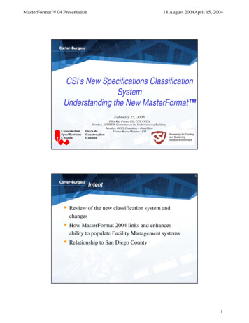
CSI SERIES GRID-TIED PV InverterCSI-4KTL1P-GI-FL & CSI-5KTL1P-GI-FLCANADIAN SOLAR INC.Global Headquarters:545 Speedvale Avenue, West Guelph, Ontario N1K 1E6, CanadaTel: 1 519 837 1881Sales Inquiries Email: sales.ca@canadiansolar.comTechnical Inquiries Email: service.ca@canadiansolar.comCANADIAN SOLAR (USA) , INC.North America Headquarters:3000 Oak Road, Ste 400, Walnut Creek, CA 94596Tel: 1 888 998 7739Sales Inquiries Email: sales.us@canadiansolar.comTechnical Inquiries Email: service.ca@canadiansolar.comEurope, Middle East & AfricaCanadian Solar EMEA GmbHLandsberger Strasse 94, 80339 Munich, GermanyTel.: 49 89 5199689 0E-mail: service.emea@canadiansolar.comThis manual is subject to change without prior notification. Copyright isreserved. Duplication of any part of this issue is prohibited without writtenpermission.INSTALLATION AND OPERATION MANUALVERSION 1.1
Contents1. Introduction 1.1 Product Description 1.2 Packaging 2. Safety Instructions 2.1 Safety Symbols 2.2 General Safety Instructions 3345552.3 Notice For Use 673. Overview 3.1 Front Panel Display7 3.2 LED Status Indicator Lights7 3.3 Keypad8 83.4 LCD 4. Installation9 94.1 Select Location for the Inverter 4.2 Mounting the Inverter 114.3 Electrical Connections 134.3.1 Connect PV side of inverter 134.3.2 Connect grid side of inverter 164.3.3 External ground connection 184.3.4 Max. overcurrent protection device (OCPD) 194.3.5 Inverter monitoring connection 194.3.6 Electrical connection diagram20 4.3.7 Meter Connection (optional) 204.3.8 CT connections (optional) 214.3.9 Logic interface connection (Only for UK)225. Start & Stop23 235.1 Start the Inverter 5.2 Stop the Inverter23 6. Operation 246.1 Main Menu 246.2 Information 246.2.1 Lock screen 26
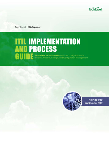
Contents 6.3.1 Set Time 6.3.2 Set Address 6.4 Advanced Info. 6.4.1 Alarm Message 6.4.2 Running Message 6.4.3 Version 6.4.4 Daily Energy 6.4.5 Monthly Energy and Yearly Energy 6.4.6 Daily Record 6.4.7 Communication Data 6.4.8 Warning Message 6.5 Advanced Settings 6.5.1 Select Standard 6.5.2 Grid ON/OFF 6.5.3 Clear Energy 6.5.4 Reset Password 6.5.5 Power Control 6.5.6 Calibrate Energy 6.5.7 Special Settings 6.5.8 STD. Mode Settings 6.5.9 Restore Settings 6.5.10 HMI Update 6.5.11 Export Power Set 6.5.12 Restart HMI 6.5.13 Debug Parameter 6.5.14 DSP Update 6.5.15 Power Parameter 7. Maintenance 8. Troubleshooting 9. Specifications 37373738384110. Installation and commissioning checklist 446.3 Settings1. Introduction1.1 Product DescriptionCanadian Solar 4G single phase inverters integrate DRM and backflow power controlfunction, that could suitable for smart grid requirement.Single phase 4G series inverter contain 2 models which are listed below:CSI-4KTL1P-GI-FL, CSI-5KTL1P-GI-FLLED lightsLCD display4 buttonsDC Switch(optional)DC inputFigure 1.1 Front side viewRS 485CT or Meter inputAC outputFigure 1.2 Bottom side view.3.
1. Introduction2.Safety InstructionsImproper use may result in potential electric shock hazards or burns. This manual1.2 Packagingcontains important instructions that should be followed during installation andWhen you receive the inverter, ensure that all the parts listed below are included:maintenance. Please read these instructions carefully before use and keep them forfuture reference.2.1 Safety SymbolsSafety symbols used in this manual, which highlight potential safety risks and importantsafety information, are listed as follows:WARNING:WARNING symbol indicates important safety instructions, which if notcorrectly followed, could result in serious injury or death.NOTE:21NOTE symbol indicates important safety instructions, which if not correctlyfollowed, could result in some damage or the destruction of the inverter.3CAUTION:CAUTION, RISK OF ELECTRIC SHOCK symbol indicates important safetyinstructions, which if not correctly followed, could result in electric shock.CSI SERIES GRID-TIED PV InverterCSI-4KTL1P-GI-FL & CSI-5KTL1P-GI-FLINSTALLATION AND OPERATION MANUALVERSION 1.1CAUTION:CAUTION, HOT SURFACE symbol indicates safety instructions, which if notcorrectly followed, could result in burns.45Part #6Description8Number2.2 General Safety InstructionsWARNING:Only devices in compliance with SELV (EN 69050) may be connected to the1PV grid tie inverter1RS485 and USB interfaces.2Wall/pole bracket1WARNING:3Locking screws24DC connector2 pairs5AC connector16RJ45 connector (Only for UK)17WiFi/GPRS Stick (Optional)18Manual1Table 1.1 Parts list.4.7Please don’t connect PV array positive( ) or negative(-) to ground, it couldcause serious damage to the inverter.WARNING:Electrical installations must be done in accordance with the local and nationalelectrical safety standards.WARNING:Do not touch any inner live parts until 5 minutes after disconnection fromthe utility grid and the PV input.5.
3. Overview2.Safety InstructionsWARNING:To reduce the risk of fire, over-current protective devices (OCPD) arerequired for circuits connected to the Inverter.The DC OCPD shall be installed per local requirements. All photovoltaic sourceand output circuit conductors shall have disconnects that comply with the NECArticle 690, Part II. All Canadian Solar single phase inverters feature anintegrated DC switch.3.1 Front Panel DisplayCAUTION:Risk of electric shock. Do not remove cover. There is no user serviceableparts inside. Refer servicing to qualified and accredited service technicians.CAUTION:The PV array (Solar panels) supplies a DC voltage when they are exposed tosunlight.CAUTION:Risk of electric shock from energy stored in capacitors of the Inverter. Do notremove cover for 5 minutes after disconnecting all power sources(service technicianonly). Warranty may be voided if the cover is removed without unauthorized .CAUTION:The surface temperature of the inverter can reach up to 75 (167 F).To avoid risk of burns, do not touch the surface of the inverter while it’s operating.Inverter must be installed out of the reach of children.PV module used with inverter must have an IEC 61730 Class A rating.2.3 Notice For UseThe inverter has been constructed according to the applicable safety and technicalguidelines. Use the inverter in installations that meet the following specifications ONLY:Figure 3.1 Front Panel Display3.2 LED Status Indicator LightsThere are three LED status indicator lights in the front panel of the inverter. Left LED:POWER LED (red) indicates the power status of the inverter. Middle LED: OPERATIONLED (green) indicates the operation status. Right LED: ALARM LED (yellow) indicatesthe alarm status. Please see Table 3.1 for detailsLightOPERATIONThe inverter can detect DC powerOFFNo DC power or low DC powerONThe inverter is operating properly.OFFThe inverter has stopped to supply power.FLASHING3.The inverter must be installed according to the instructions stated in this manual.4.The inverter must be installed according to the correct technical specifications.5.To startup the inverter, the Grid Supply Main Switch (AC) must be switched on, beforeONPOWER1.Permanent installation is required.2.The electrical installation must meet all the applicable regulations and standards.DescriptionStatusALARMThe inverter is initializing.ONAlarm or fault condition is detected.OFFThe inverter is operating without fault or alarm.the solar panel's DC isolator shall be switched on. To stop the inverter, the Grid SupplyMain Switch (AC) must be switched off before the solar panel's DC isolator shall beTable 3.1 Status Indicator Lightsswitched off.6.7.
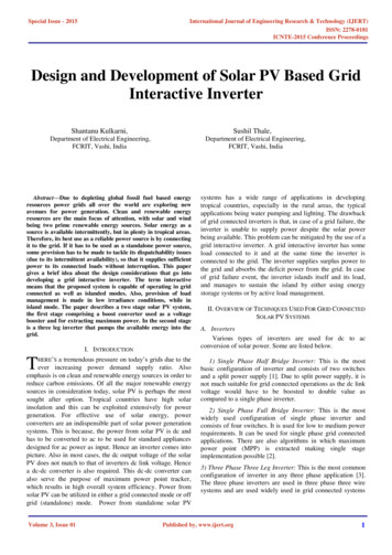
4. Installation3. Overview3.3 KeypadThere are four keys in the front panel of the Inverter(from left to right):ESC, UP, DOWN and ENTER keys. The keypad is used for:4.1 Select a Location for the InverterTo select a location for the inverter, the following criteria should be considered:Do not install in small closed spaces where air can not circulate freely. To avoidoverheating, always make sure the flow of air around the inverter is not blocked.Scrolling through the displayed options (the UP and DOWN keys);Access to modify the adjustable settings (the ESC and ENTER keys).Exposure to direct sunlight will increase the operational temperature of the inverter andmay cause output power limiting. Canadian Solar recommends inverter installed to avoiddirect sunlight or raining.3.4 LCDThe two-line Liquid Crystal Display (LCD) is located on the front panel of the Inverter,To avoid over heating ambient air temperature must be considered when choosing theinverter installation location. Canadian Solar recommends using a sun shade minimizingdirect sunlight when the ambient air temperature around the unit exceeds 104 F/40 C.which shows the following information:Inverter operation status and data;Service messages for operator;Alarm messages and fault indications.Figure 4.1 Recommended Installation locations.8.9.
4. Installation4. Installation4.2 Mounting the InverterInstall vertically with a maximum incline of /- 5 .If the mounted inverter is tilted to anDimensions of wall bracket:angle greater than the maximum noted, heat dissipation can be inhibited, and may resultin less than expected output power.When 1 or more inverters are installed in one location, a minimum 12inchs clearanceshould be kept between each inverter or other object. The bottom of the inverter should300mm300mmbe 20inchs clearance to the ground.Figure 4.3 Inverter wall mounting300mm300mm300mmPlease see Figure 4.4 and Figure 4.5 for instruction on mounting the inverter.The inverter shall be mounted vertically. The steps to mount the inverter are listed below:1. According to the figure 4.2, select the mounting height of the bracket and mark the500mm500mmmounting holes. For brick walls, the position of the holes should be suitable for theexpansion bolts.BracketFigure 4.2 Inverter Mounting clearanceVisibility of the LED status indicator lights and the LCD located at the front panel ofthe inverter should be considered.Adequate ventilation must be provided if the inverter is to be installed in a confined space.NOTE:Nothing should be stored on or placed against the inverter.Suitable fixing screwsFigure 4.4 Inverter wall mounting.10.11.
4. Installation4. Installation4.3 Electrical Connections2.Make sure the bracket is horizontal and the mounting holes (in Figure 4.4 )are marked correctly. Drill the holes into the wall or pillar at your marks.3.Use the suitable screws to fix the bracket to the wall.WARNING:The inverter must be mounted vertically.4.3.1 Connect PV side of inverterThe electrical connection of the inverter must follow the steps listed below:1. Switch the Grid Supply Main Switch (AC) OFF.2. Switch the DC Isolator OFF.3. Assemble PV input connector to the Inverter.4.Lift up the inverter (be careful to avoid body strain), and align the back bracket on theinverter with the convex section of the mounting bracket. Hang the inverter on theBefore connecting inverter, please make sure the PV array open circuit voltage iswithin the limit of the invertermounting bracket and make sure the inverter is secure (see Figure 4.5).Maximum 600Voc forCSI-4KTL1P-GI-FL CSI-5KTL1P-GI-FLLocking screwsPlease don’t connect PV array positive or negative pole to the ground, it couldcause serious damages to the inverter.Before connection, please make sure the polarity of the output voltage of PV arraymatches the“DC ”and “DC-”symbols.Figure 4.5 Wall Mount Bracket5. Use M4*9 screws in accessory to lock the inverter to the mount bracket.Figure 4.6 DC Connector.12.Figure 4.7 DC- Connector.13.
4. Installation4. InstallationPlease use approved DC cable for PV system.Cable typeIndustry generic PV cable(model:PV1-F)iii) Crimp the contact pin to the wire using a proper wire crimper.Cross sectionRangeRecommendedvalue4.0 6.04.0(12AWG)(12 10AWG)Crimping plierTable 4.1 DC cableFigure 4.10 Crimp the contact pin to the wireThe steps to assemble the DC connectors are listed as follows:I) Strip off the DC wire for about 7mm, Disassemble the connector cap nut.iv) Insert the contact pin to the top part of the connector and screw up the cap nut tothe top part of the connector.Figure 4.8 Disassemble the Connector Cap nutFigure 4.11 Connector with Cap nut Screwed onii) Insert the wire into the connector cap nut and contact pin.v) Then connect the DC connectors to the inverter. Small click will confirm connection.Figure 4.9 Insert the Wire into the Connector Cap nut and contact pinFigure 4.12 Connect the DC Connectors to the Inverter.14.15.
4. Installation4. Installation4.3.2 Connect grid side of inverterFor all AC connections, 2.5- 6mm 2 105 cable is required to be used. Please make surethe resistance of cable is lower than 1 ohm. If the wire is longer than 20m, it's recommendedto use 6mm 2 cable.The steps to assemble the AC grid terminal connectors are listed as follows:a) Disassemble the AC connector. Strip the AC wires about 6mm.WARNING:There aresymbols marked inside the connector , the Linewire of grid must be connected to“L”terminal; the Neutral wireof grid mustbe connected to“N”terminal; the Earth of grid must be connectedto“ ”(see Figure 4.13).Cable typeIndustry genericgrid cableCross sectionRangeRecommendedvalue2.5 6.0mm²6mm²Figure 4.15 Stripped AC Wiresb) Fix the green and yellow wire to the ground terminal. Fix the red(or brown) wire to LTable 4.2 Grid cable size(line) terminal. Fix the blue wire to N(Neutral). Tight the screws on the connector.Please try to pull out the wire to make sure the it’s well connected.Figure 4.13 AC Grid Terminal Connector InsideEach Canadian Solar Single Phase Inverter is supplied with an AC grid terminal connector.Figure 4.16 Connect Wires to the Terminalc) Tighten up the cap on the terminal (see Figure 4.17).Figure 4.14 AC Grid Terminal Connector.16.Figure 4.17 Tighten up the Cap on the Terminal.17.
4. Installation4. Installation4.3.4 Max. over current protection device (OCPD)d) Connect the AC grid terminal connector to the inverter. Small click will confirmconnection.To protect the inverter's AC grid connection conductors, Canadian Solar recommendsinstalling breakers that will protect against overcurrent. The following table defines OCPDratings for the Canadian Solar 4-5kW single phase inverters.InverterRated outputvoltage(V)Rated outputcurrent (A)Current for protectiondevice -FL220/23022.7/21.730Table 4.3 Rating of grid OCPDFigure 4.18 Connect the AC Connector to the InverterNote: Connection for Split phase grid.When connect to 208/220/240V split phase, please connect L1 to “L” terminal,L2 to “N” terminal. Also connect earth to ground terminal.4.3.5 Inverter monitoring connectionThe inverter can be monitored via Wi-Fi or GPRS. All Canadian Solar communicationdevices are optional (Figure 4.20). For connection instructions, please refer to theCanadian Solar Monitoring Device installation manuals.4.3.3 External ground connectionSmart phone monitoringAn external ground connection is provided at the right side of inverter.Prepare OT terminals: M4. Use proper tooling to crimp the lug to the terminal.GPRS monitoringConnect the OT terminal with ground cable to the right side of inverter. The torque is20 in-lbs (2Nm).InternetRouterWeb serverWi-Fi monitoringPC monitoringWi-Fi boxWi-Fi monitoringFigure4.20 Wi-Fi or GPRS communication functionFigure 4.19 Connect the external grounding conductor.18.19.
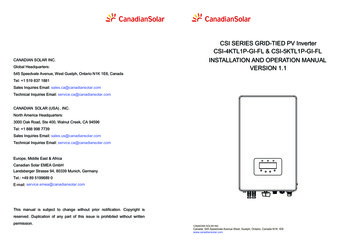
4. Installation4. Installation4.3.6 Electrical connection diagramCommunicationRefer to figure 4.21, which is a simple guidance for installing a solar system with PV inverter.A DC isolator is required to be installed in the system between PV panels with inverter.5 6 7 8A BDDSD1352220V 10(60)AConsumersmains(to grid)1MAIN SWITCHBOARDMainswitch1T1T2T31600 imp/kWhIsolation deviceSolar supplymain switch1Inverter withintegral gridProtection deviceSolar(PV)arrayMENUL L N N 2Isolation switchGridLoadFigure 4.23 Meter in GridCircuits not Circuits Protectedprotected byby RCDsRCDs4.3.8 CT connections(optional)Figure 4.21 Guidance for a Simple Installation of an Inverter Solar Energy System1. The RCD should be in parallel connection between the consumers mains and the solar supply.2. More than one RCD may be used. Each RCD can protect one or more circuits.4.3.7 Meter Connection(optional)The inverter has intergrated export limitation functionality.To use this function , a power meter or a CT must be installed , if use the power meter, it shouldbe installed in the load side or in the grid side , Because the meter used in the single-phaseinverter is divided into two types: single-direction meter, and dual-direction meter. Therefore,the wiring method is divided into two cases. The dual-direction meter corresponds to the meterin grid connection mode; the single-direction meter corresponds to the meter in load connectionmode. see Figure 4.22 and 4.23. After the inverter power on , please set the correspondingconfiguration as sections 6.5.11.1.2 and 6.5.11.1.3.This inverter has integrated export limitation functionality. To use this function, a powermeter or a CT must be installed , if use the CT, please reference below picture. The CTshould be fitted around the live conductor on the grid side of the main incoming consumerunit. Use the directional flow indication arrow on the CT to ensure it is fitted in the correctorientation. The arrow should be pointing towards the grid, not the load. when the inverterpower on, please set the corresponding configuration as sections 6.5.11.1.4.1 and 6.5.11.1.4.2.InverterCT Input L NLCTNCommunicationL NLoad5 6 7 8A BDDSD1352220V 10(60)A1T1T2GridT31600 imp/kWhFigure 4.24 Direction of CTMENUL L N N GridLoadFigure 4.22 Meter in Load.20.21.
4. Installation5. Start & Stop4.3.9 Logic interface connection (Only for UK)Logic interface is required by G98 and G99 standard that can be operated by a simple switchor contactor. When the switch is closed the inverter can operated normally. When the switchis opened, the inverter will reduce it’s output power to zero within 5s.Pin5 and Pin6 of RJ45 terminal is used for the logic interface connection.Please follow below steps to assemble RJ45 connector.1.Insert the network cable into the communication connection terminal of RJ45.(As shown in figure 4.25)5.1 Start the InverterTo start up the Inverter, it is important that the following steps are strictly followed:1. Switch the grid supply main Switch (AC) ON first.2. Switch the DC switch ON. If the voltage of PV arrays are higher than start up voltage,the inverter will turn on. The red LED power will light.3. When both the DC and the AC sides supply to the inverter, it will be ready to generatepower. Initially, the inverter will check both its internal parameters and the parametersof the AC grid, to ensure that they are within the acceptable limits. At the same time,the green LED will flash and the LCD displays the information of INITIALIZING.4. After 30-300 seconds (depending on local requirement), the inverter will start toFigure 4.25 RJ45 communication connection terminalsgenerate power. The green LED will be on continually and the LCD displaysGENERATING.2.Use the network wire stripper to strip the insulation layer of the communication cable.According to the standard line sequence of figure 4.26 connect the wire to the plug ofRJ45, and then use a network cable crimping tool to make it tight.Rj45 plug1--8Rj45terminal1234567812345678Switch input1Switch input2DRM(logic interface)Correspondence between the cable sand the stitch es of plug, Pin5 and Pin6of RJ45 terminal is used for the logicinterface, other Pins are reserved.Pin 1: Reserved; Pin 2: ReservedPin 3: Reserved; Pin 4: ReservedPin 5: Switch input1; Pin 6: Switch input2Pin 7: Reserved; Pin 8: ReservedWARNING:Do not touch the surface when the inverter is operating. It may behot and cause burns.5.1.1 Inverter working statusWhen inverter working normally,there would be 5 status :Generating:Inverter is working normallyLimByTemp: Inverter power limited by over ambient temperature.LimByFreq: Inverter power limited by over grid frequencyLimByVg: Inverter power limited by over grid voltageLimByVar: Inverter power limited by generating reactive power.5.2 Stop the InverterFigure 4.26 Strip the insulation layer and connect to RJ45 plug3.Connect RJ45 to DRM (l ogic interface ) .After wire connection, please refer chapter 6.5.8.1 to enable the logic interface function.22.To stop the Inverter, the following steps must be strictly followed:1. Switch the Supply Main Switch (AC) OFF.2. Wait 30 seconds. Switch the DC Switch OFF. All the LEDs of the inverter will be off in oneminute.23.
6. Operation6. OperationDuring normal operation, the display alternately shows the power and the operationstatus with each screen lasting for 10 seconds (see Figure 6.1). Screens can also bescrolled manually by pressing the UP and DOWN keys. Press the ENTER key toaccess to the Main Menu.Pressing theESC keycalls back theprevious menu.Power3424W01-01-2014 12:04DisplayDurationV DC1 350.8VI DC15.1A10 secV DC2 350.8VI DC25.1A10 secMain MenuInformationUP/DOWN5 secUP/DOWN orauto-scroll(10 sec)UP/DOWNV DC1: Shows input 01 voltage value.I DC1: Shows input 01 current value.V DC2: Shows input 02 voltage value.I DC2: Shows input 02 current value.V Grid: Shows the grid's voltage valueV Grid 230.4VI Grid8.1A10 secStatus: GeneratingPower: 1488W10 secGrid FrequencyF Grid 60.06Hz10 secF Grid: Shows the grid's frequency value.Total Energy0258458 kwh10 secTotal generated energy value.This Month: 0123kwhLast Month: 0123kwh10 secToday:15.1kwhYesterday: 13.5kwh10 secSettingsStartDescriptionI Grid: Shows the grid's current value.Status: Shows instant status of the Inverter.Power: Shows instant output power value.Advanced Info.Status: Generating01-01-2014 12:04Pressing theENTER keygives access tothe main menu.UP/DOWNAdvanced settingsFigure 6.1 Operation Overview6.1 Main MenuThere are four submenus in the Main Menu (see Figure 6.1):1. InformationInverter SN0000000000000010 secExport P:Export I: 0000W00.0A10 secWork Mode:NULLDRM Number:0810 sec2. Settings3. Advanced Info.4. Advanced Settings6.2 InformationMeter EnergyPThe Canadian Solar Single Phase 4G Inverter main menu provides access to operational0000000.00k Wh10 secThis Month: Total energy generated this month.Last Month: Total energy generated last month.Today: Total energy generated today.Yesterday: Total energy generated yesterday.Display series number of the inverter.Power of ERM.Current of EPM.Work Mode:The work mode of inverter.DRM Number:Show the number 01-08.Meter EnergyP:The active power.data and information. The information is displayed by selecting "Information" from the menuand then by scrolling up or down.24.Table 6.1 Information list.25.
6. Operation6. Operation6.2.1 Lock screenYES ENT NO ESC Set Address: 01Pressing the ESC key returns to the Main Menu. Pressing the ENTER key locks(Figure 6.2(a)) or unlocks (Figure 6.2 (b)) the screen.Figure 6.4 Set AddressPress the UP/DOWN keys to set the address. Press the ENTER key to save the settings.Press the ESC key to cancel the change and return to the previous menu.5.2 Stop the Inverter (a)(b)Figure 6.2 Locks and Unlocks the Screen of LCD6.4 Advanced Info - Technicians OnlyNOTE:To access to this area is for fully qualified and accredited technicians only.Enter menu “Advanced Info.” and “Advanced settings” (need password).6.3 SettingsThe following submenus are displayed when the Settings menu is selected:1.Set TimeSelect “Advanced Info.” from the Main Menu. The screen will require the password as below2.Set AddressYES ENT NO ESC Password:00006.3.1 Set TimeFigure 6.5 Enter passwordThis function allows time and date setting. When this function is selected, the LCD willdisplay a screen as shown in Figure 6.3.The default password is “0010". Please press “down” to move the cursor, press “up” toselect the number.NEXT ENT OK ESC 01-01-2016 16:37After enter the correct password the Main Menu will display a screen and be able to accessto the following information.Figure 6.3 Set TimePress the UP/DOWN keys to set time and data. Press the ENTER key to move from onedigit to the next (from left to right). Press the ESC key to save the settings and return tothe previous menu.6.3.2 Set AddressThis function is used to set the address when muti inverters are connected to single monitor.1.Alarm Message 2. Running Message 3.Version 4. Daily Energy 5. Monthly Energy6. Yearly Energy 7. Daily Record 8.Communication Data 9.Warning MessageThe screen can be scrolled manually by pressing the UP/DOWN keys. Pressing the ENTERkey gives access to a submenu. Press the ESC key to return to the Main Menu.6.4.1 Alarm MessageThe display shows the 100 latest alarm messages (see Figure 6.6). Screens can be scrolledThe address number can be assigned from “01”to “99”(see Figure 6.4). The default addressmanually by pressing the UP/ DOWN keys. Press the ESC key to return to the previousnumber of Canadian Solar Single Phase Inverter is “01”.menu.Alarm001: OV-G-VTime: 27-11 Data: 7171Figure 6.6 Alarm Message.26.27.
6. Operation6. OperationPress DOWN key to move the cursor, press UP key to change the digit.6.4.2 Running MessageThis function is for maintaince person to get running message such as internal temperature,Press Enter after the month/year is fixed.2015-02: 0510kWh2015-01: 0610kWhStandard NO. etc.Screens can be scrolled manually by pressing the UP/DOWN keys.2015: 0017513kWh2014: 0165879kWhFigure 6.12 Month energy6.4.3 VersionFigure 6.13 Yearly energyPress UP/DOWN key to move one date from another.The screen shows the model version and the software version of the Inverter(see Figure 6.7).Model: 08Software Version: D200016.4.6 Daily recordThe screen shows history of changing settings. Only for maintance personel.6.4.7 Communication DataFigure 6.7 Model Version and Software VersionThe screen shows the internal data of the Inverter (see Figure 6.14), which is for servicetechnicians only.6.4.4 Daily Energy01-05: 01 25 E4 9D AA06-10: C2 B5 E4 9D 55The function is for checking the energy generation for selected day.YES ENT NO ESC Select: 2015-02-23Figure 6.14 Communication Data6.4.8 Warning MessageFigure 6.8 Select date for daily energyPress DOWN key to move the cursor to day, month and year, press UP key to change theThe display shows the 100 latest warn messages (see Figure 6.15). Screens can be scrolledmanually by pressing the UP/ DOWN keys. Press the ESC key to return to the previous menu.digit. Press Enter after the date is fixed.Msg000:T: 00-00 00:00 D:00002015-02-22: 051.3kWh2015-02-23: 061.5kWhFigure 6.15 Warning MessageFigure 6.9 Daily energy6.5 Advanced Settings - Technicians OnlyPress UP/DOWN key to move one date from another.6.4.5 Monthly Energy and Yearly EnergyNOTE:To access to this area is for fully qualified and accredited technicians only.Please follow 6.4 to enter password to access this menu.The two functions are for checking the energy generation for selected month and YearSelect Advanced Settings from the Main Menu to access the following options:YES ENT NO ESC Select: 2015-02Figure 6.10 Select month for monthly energyYES ENT NO ESC Select: 2015Figure 6.11 Select year for yearly energy1.Select Standard2.Grid ON/OFF3.Clear Energy4. Reset Password5. Power Control 6.Calibrate Energy 7.Special Settings8.STD. Mode Settings9.Restore Settings 10.HMI Update 11.Export Power Set 12.Restart HMI13.Debug Parameter 14.DSP Update 15.Power Parameter.28.29.
6. Operation6. Operation6.5.1 Selecting StandardThis function is used to select the grid's reference standard (see Figure 6.16).YES ENT NO ESC Standard:AS4777-02NOTE:This inverter inclding two level protections for voltage and frequencyunder user-def mode; please set the same value both level one andlevel two if the gird only have one level requriement, eg. Brazil.etc.Press the UP/DOWN keys to scroll through items. Press the ENTER key to edit theFigure 6.16Press the UP/DOWN keys to select the standard (AS4777-02,AS4777-15, VDE4105, VDE0126,highlighted item. Press the UP/DOWN keys again to change the setting. Press the ENTERkey to save the setting. Press the ESC key to cancel changes and returns to the previous menu.UL-240V-A, UL-208V-A, UL-240V, UL-208V, MEX-CFE, G83/2 (for 1-3.6kW models), G59/3(for 4-5kW models), EN50438 DK, EN50438 IE, EN50438 NL and “User-Def” function).6.5.2 Grid ON/OFFPress the ENTER key to confirm the setting. Press the ESC key to cancel changes and returnsThis function is used to start up or stop the power generation of Canadian Solar Single Phaseto previous menu.Inverter (see Figure 6.18).Grid ONGrid OFFNOTE:This function is for technicians use only.Figure 6.18 Set Grid ON/OFFSelecting the “User-Def” menu will access to the following submenu (see Figure 6.17),Screens can be scrolled manually by pressing the UP/DOWN keys. Press the ENTER keyOV-G-V1: 260VOV-G-V1-T: 1SFigure 6.17NOTE:The " User-Def" function can be only used by the service engineer andmust be allowed by the local energy supplier.Below is the setting range for “User-Def”. Using this function, the limits can be changedto save the setting. Press the ESC key to return to the previous menu.6.5.3 Clear EnergyClear Energy can reset the h
2. The electrical installation must meet all the applicable regulations and standards. 3. The inverter must be installed according to the instructions stated in this manual. 4. The inverter must be installed according to the correct technical specifications. 5. To startup the inverter, the Grid Supply Main Switch (AC) must be switched on, before