Transcription
Solar PV Inverter Test ProceduresPrepared for:Joe EtoLawrence Berkeley National LaboratoryPrepared by:Richard Bravo, Steven RoblesAdvanced Technology, Engineering & Technical Services, SCEDecember 30, 2013
Solar PV Inverter Test ProceduresSouthern California Edison (SCE), an Edison International company, is one of the nationslargest investor-owned utilities, serving nearly 14 million people in a 50,000-square-mileservice area within Central, Coastal and Southern California. The utility has been providingelectric service in the region for more than 120 years.SCE’s service territory includes about 430 cities and communities with a total customer base of4.9 million residential and business accounts. SCE is regulated by the California Public UtilitiesCommission and the Federal Energy Regulatory Commission.In 2012, SCE generated about 25 percent of the electricity it provided to customers, with theremaining 75 percent purchased from independent power producers. One of the nation’sleading purchasers of renewable energy, SCE delivered nearly 15 billion kilowatt-hours ofrenewable energy to its customers in 2012, enough to power 2.3 million homes.Advanced Technology is the organization in SCE’s Transmission and Distribution business unitand Engineering & Technical Services (E&TS) division that investigates advancedtechnologies and methodologies to support the utility’s goals to provide safe, reliable andaffordable energy while overcoming the challenges associated with the generation,transmission and distribution of electricity such as: the integration of variable energyresources, cascading outages and the effects of loads. Southern California Edison 2013Advanced Technology 14799 Chestnut Street, Westminster, California 92683 USA Phone: (714) 934-0818DER Laboratory ResearchPage 2 of 62
Solar PV Inverter Test ProceduresSCE DISCLAIMER OF WARRANTIES AND LIMITATION OF LIABILITIESThe work described in this report was coordinated by the Consortium for Electric ReliabilityTechnology Solutions and funded by the Office of Electricity Delivery and Energy Reliability ofthe U.S. Department of Energy under Contract No. DE-AC02-05CH1123 through a subcontractwith Southern California Edison administered by the Lawrence Berkeley National Laboratory.This report was created as a result of work sponsored by the U.S. Department of Energythrough the Lawrence Berkeley National Laboratory and SCE's Research Development andDemonstration Balancing Account, which was initially established in 1988 as part of customerrates and performed by its Advanced Technology organization. This report has not beenapproved or disapproved by SCE nor has SCE verified the accuracy, adequacy, and safety ofthe information in this report.Neither Advanced Technology, SCE, Edison International, nor any person working for or onbehalf of any of these entities, makes any warranty or representation, express or implied,related to this report. Without limiting the foregoing, SCE expressly disclaims any liabilityassociated with the following: (i) information, products, processes or procedures discussed inthis report, including the merchantability and fitness for a particular purpose of these, (ii) use ofthe test procedure or that this use does not infringe upon or interfere with rights of others,including another’s intellectual property, and (iii) that this report is suitable to any particularuser’s circumstance.SCE follows OSHA and internal safety procedures to protect its personnel and encourages itspartners and contractors to these safety practices as well.The author acknowledges the additional support of LBNL independent consultant, John Kueck,and SCE intern Shruthi Sama who provided valuable contribution in the development of thisprocedure. Southern California Edison 2013Advanced Technology 14799 Chestnut Street, Westminster, California 92683 USA Phone: (714) 934-0818DER Laboratory ResearchPage 3 of 62
Solar PV Inverter Test ProceduresLBNL DISCLAIMER OF WARRANTIES AND LIMITATION OF LIABILITIESThis document was prepared as an account of work sponsored by the United StatesGovernment. While this document is believed to contain correct information, neither the UnitedStates Government nor any agency thereof, nor The Regents of the University of California,nor any of their employees, makes any warranty, express or implied, or assumes any legalresponsibility for the accuracy, completeness, or usefulness of any information, apparatus,product, or process disclosed, or represents that its use would not infringe privately ownedrights. Reference herein to any specific commercial product, process, or service by its tradename, trademark, manufacturer, or otherwise, does not necessarily constitute or imply itsendorsement, recommendation, or favoring by the United States Government or any agencythereof, or The Regents of the University of California. The views and opinions of authorsexpressed herein do not necessarily state or reflect those of the United States Government orany agency thereof, or The Regents of the University of California.Ernest Orlando Lawrence Berkeley National Laboratory is an equal opportunity employer. Southern California Edison 2013Advanced Technology 14799 Chestnut Street, Westminster, California 92683 USA Phone: (714) 934-0818DER Laboratory ResearchPage 4 of 62
Solar PV Inverter Test ProceduresTABLE OF CONTENTS1.02.0OBJECTIVE . 6SOLAR PV INVERTER INSTALLATION AND SETUP. 82.12.22.33.0INVERTER DC PERFORMANCE TEST . 143.13.23.34.0Test 1 – Inverter Output Time Delay Test . 17Test 2 – Inverter Anti-Island Test . 19Test 3 – Under-Voltage Transients Test . 21Test 4 – Over-Voltage Transients Test . 24Test 5 – Voltage-Oscillation Test . 27Test 6 – Under-Frequency Fluctuations Test . 29Test 7 – Over-Frequency Fluctuations Test . 32Test 8 – Frequency Oscillation Test . 35Test 9 – Voltage Ramp Test . 37Test 10 – Frequency Ramp Test. 39Test 11 – Conservation Voltage Reduction (CVR) Test . 41Test 12 – Harmonics Data Recording . 43Test 13 – Short Circuit Test . 453-PHASE INVERTER AC PERFORMANCE TESTS. 475.15.26.0Test 1 – Inverter “DC On” Time Delay Test . 14Test 2 – Inverter “DC Off” Delay Test. 15Test 3 – Irradiance Profile Test . 16INVERTER AC PERFORMANCE TESTS . verter Setup . 9Inverter Measurements . 11Personnel Safety . 13Test 1 – Unbalanced Under-Voltage Transients Test. 47Test 2 – Unbalanced Over-Voltage Transients Test. 49INVERTER ADVANCED FEATURES PERFORMANCE TESTS . 516.16.26.36.46.56.6Test 1 – Start-Up Power Ramp-Up Rates . 51Test 2 – Voltage Ride-Through . 53Test 3 – Over-Frequency Power Curtailment . 55Test 4 – Autonomous Power Factor Adjustment . 57Test 5 – Autonomous Voltage Support (Under-Voltage) . 59Test 6 – Autonomous Voltage Support (Over-Voltage) . 61 Southern California Edison 2013Advanced Technology 14799 Chestnut Street, Westminster, California 92683 USA Phone: (714) 934-0818DER Laboratory ResearchPage 5 of 62
Solar PV Inverter Test Procedures1.0 OBJECTIVEThe increase in fossil-based energy costs and demand for cleaner energy sources has led toan exponential growth in renewable generation. The State of California is known for itsambitious initiatives to achieve 33 percent of its electricity from renewables by 2020, primarilythis comes from wind and solar generation. The California Solar initiative providing rebates andincentives for residential and commercial customers to install solar photovoltaic (PV)generation at their premises is expected to result in even greater amounts of residential solargeneration interconnecting with the electric grid in the near the future. Safely and efficientlymanaging the addition of all this solar energy requires being able to conduct appropriatestudies and accurate assessments of how the integration of this type of generation and thetechnology advancements being developed will impact in the grid.Southern California Edison (SCE) is planning on installing 125 MW of solar PV generation andan additional 375 MW is expected by private parties. Working alone and in collaborations withother entities, such as the National Renewable Electric Laboratory (NREL), the company hasbeen testing solar PV inverters. The test data collected by SCE engineers can be used todevelop and validate solar PV models, which can be used to determine how this particulartechnology impacts the grid.The objectives of the inverter testing are to: Investigate the dynamic performance of inverters during voltage and frequency fluctuationsand oscillations typically found on the grid Understand smart inverters features behaviors Analyze test data to determine whether these inverters are grid-friendly devices and/orwhat needs to be done to ensure they will be in the near future Contribute to the development, testing, and/or validation of solar PV inverter models thatcan eventually be used in dynamic, steady-state, and harmonic system impact studiesSCE believes sharing these test procedures will encourage the inverter manufacturers toparticipate in additional testing, and will initiate a constructive dialog about how to offer Southern California Edison 2013Advanced Technology 14799 Chestnut Street, Westminster, California 92683 USA Phone: (714) 934-0818DER Laboratory ResearchPage 6 of 62
Solar PV Inverter Test Procedurestechnologies that address the consumer’s needs while ensuring electric utilities are able tomaintain and improve the reliability of the grid, especially with greater penetration of thesetypes of devices. Southern California Edison 2013Advanced Technology 14799 Chestnut Street, Westminster, California 92683 USA Phone: (714) 934-0818DER Laboratory ResearchPage 7 of 62
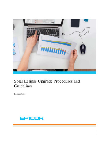
Solar PV Inverter Test Procedures2.0 SOLAR PV INVERTER INSTALLATION AND SETUPFigure 2.0.1 shows the typical test setup diagram of various devices used in the testing of thesolar PV inverters. The equipment required for the SCE Solar PV Inverter Test Procedure are: Grid simulator (GS): supplies typical actual voltage and frequency deviations Solar PV Simulator (PVS): Emulates solar PV panel performance Equipment under test (EUT): Solar PV inverter (1-phase or 3-phase inverter) Load Bank (LB): Real and reactive load variable impedance Power analyzer (PA): records voltage and current raw data at high sampling rates Computer (CPU): control the grid simulator and power analyzerThe digital scope will record the raw voltage and current data at a high sampling rate specifiedfor each test and will calculate other parameters such as real, reactive power, frequency, andharmonics.Figure 2.0.1Test Setup Block Diagram Southern California Edison 2013Advanced Technology 14799 Chestnut Street, Westminster, California 92683 USA Phone: (714) 934-0818DER Laboratory ResearchPage 8 of 62
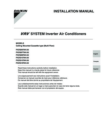
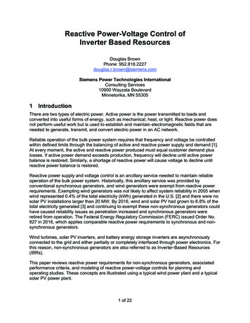
Solar PV Inverter Test Procedures2.1 Inverter SetupThe test setup should employ the necessary protection equipment such as circuitbreakers and/or fuses to disconnect the circuit in the event of short circuits. A circuitbreaker should be used to provide protection between the DC source and the inverterinput as well the AC source and the inverter output. The grid simulator has additionalinternal multiple protection mechanisms; one input circuit breaker, one output circuitbreaker, a power contactor, and multi-protection mechanisms.Inverter tests must be performed using the appropriate setups for split-phase and threephase testing. Figure 2.1.1 and Figure 2.1.2 show the typical wiring diagrams for bothsplit-phase and three-phase testing respectively.Figure 2.1.1 The Split-Phase Test Setup Wiring Diagram Southern California Edison 2013Ad
The equipment required for the SCE Solar PV Inverter Test Procedure are: Grid simulator (GS): supplies typical actual voltage and frequency deviations Solar PV Simulator (PVS): Emulates solar PV panel performance Equipment under test (EUT): Solar PV inverter (1-phase or 3-phase inverter) Load Bank (LB): Real and reactive load variable impedance Power analyzer (PA): records .