Transcription
Special Issue - 2015International Journal of Engineering Research & Technology (IJERT)ISSN: 2278-0181ICNTE-2015 Conference ProceedingsDesign and Development of Solar PV Based GridInteractive InverterSushil Thale,Shantanu Kulkarni,Department of Electrical Engineering,FCRIT, Vashi, IndiaDepartment of Electrical Engineering,FCRIT, Vashi, IndiaAbstract—Due to depleting global fossil fuel based energyresources power grids all over the world are exploring newavenues for power generation. Clean and renewable energyresources are the main focus of attention, with solar and windbeing two prime renewable energy sources. Solar energy as asource is available intermittently, but in plenty in tropical areas.Therefore, its best use as a reliable power source is by connectingit to the grid. If it has to be used as a standalone power source,some provision has to be made to tackle its dispatchability issues(due to its intermittent availability), so that it supplies sufficientpower to its connected loads without interruption. This papergives a brief idea about the design considerations that go intodeveloping a grid interactive inverter. The term interactivemeans that the proposed system is capable of operating in gridconnected as well as islanded modes. Also, provision of loadmanagement is made in low irradiance conditions, while inisland mode. The paper describes a two stage solar PV system,the first stage comprising a boost converter used as a voltagebooster and for extracting maximum power. In the second stageis a three leg inverter that pumps the available energy into thegrid.I. INTRODUCTIONa tremendous pressure on today‟s grids due to theever increasing power demand supply ratio. Alsoemphasis is on clean and renewable energy sources in order toreduce carbon emissions. Of all the major renewable energysources in consideration today, solar PV is perhaps the mostsought after option. Tropical countries have high solarinsolation and this can be exploited extensively for powergeneration. For effective use of solar energy, powerconverters are an indispensible part of solar power generationsystems. This is because, the power from solar PV is dc andhas to be converted to ac to be used for standard appliancesdesigned for ac power as input. Hence an inverter comes intopicture. Also in most cases, the dc output voltage of the solarPV does not match to that of inverters dc link voltage. Hencea dc-dc converter is also required. This dc-dc converter canalso serve the purpose of maximum power point tracker,which results in high overall system efficiency. Power fromsolar PV can be utilized in either a grid connected mode or offgrid (standalone) mode. Power from standalone solar PVTHERE‟SVolume 3, Issue 01systems has a wide range of applications in developingtropical countries, especially in the rural areas, the typicalapplications being water pumping and lighting. The drawbackof grid connected inverters is that, in case of a grid failure, theinverter is unable to supply power despite the solar powerbeing available. This problem can be mitigated by the use of agrid interactive inverter. A grid interactive inverter has someload connected to it and at the same time the inverter isconnected to the grid. The inverter supplies surplus power tothe grid and absorbs the deficit power from the grid. In caseof grid failure event, the inverter islands itself and its load,and manages to sustain the island by either using energystorage systems or by active load management.II. OVERVIEW OF TECHNIQUES USED FOR GRID CONNECTEDSOLAR PV SYSTEMSA. InvertersVarious types of inverters are used for dc to acconversion of solar power. Some are listed below.1) Single Phase Half Bridge Inverter: This is the mostbasic configuration of inverter and consists of two switchesand a split power supply [1]. Due to split power supply, it isnot much suitable for grid connected operations as the dc linkvoltage would have to be boosted to double value ascompared to a single phase inverter.2) Single Phase Full Bridge Inverter: This is the mostwidely used configuration of single phase inverter andconsists of four switches. It is used for low to medium powerrequirements. It can be used for single phase grid connectedapplications. There are also algorithms in which maximumpower point (MPP) is extracted making single stageimplementation possible [2].3) Three Phase Three Leg Inverter: This is the most commonconfiguration of inverter in any three phase application [3].The three phase inverters are used in three phase three wiresystems and are used widely used in grid connected systemsPublished by, www.ijert.org1
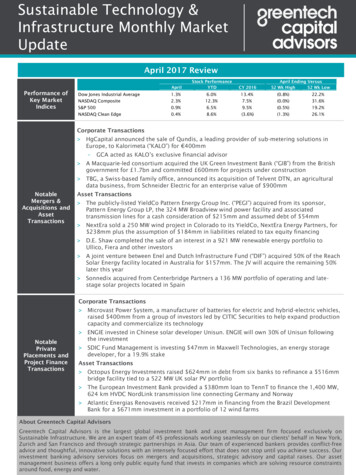
Special Issue - 2015International Journal of Engineering Research & Technology (IJERT)ISSN: 2278-0181ICNTE-2015 Conference Proceedingswith or without a transformer. They can be operated for highpower operation as well.4) Current Source Inverters: These inverters are preferred insingle stage implementation of solar PV systems where thepower conversion is from a low voltage dc input to acomparatively high voltage ac output. This kind of powertopology is seen in [4] and [5].B. Types of MPPT (Maximum power point tracking)converter topologies.Various types of topologies for mppt are used by variousresearchers. Some are listed below.1) Inverters with inbuilt MPPT function: In this case, thereis no dedicated dc-dc converter for MPP tracking. These aresingle stage systems in which MPP tracking and inversion aredone within the same stage, i.e. the inverter. Such systems arelisted in [2], [4] and [5].2) Boost converter for MPPT: This is a popular techniquein two stage systems where a separate dc-dc converter is usedto extract maximum power from solar PV because along withMPP extraction, voltage boosting is done to make the voltagesuitable to the inverters dc link voltage. Such technique isused in [3]. This paper also proposes a similar technique.3) Two inductor boost converter for MPPT: This is anotherpopular technique used for solar PV systems because alongwith boosting the solar PV voltage and extracting maximumpower, this topology also provides isolation [6].4) Resonant dc-dc converter for MPPT: Researchers arealso exploring the possibilities of the use of soft switchingconverters in MPPT. The use of a full bridge zero voltageswitching resonant step up dc-dc converter is given in [7].C. Types of Filters for Inverters [8], [9].The most common types of filters for grid connected invertersare L filter, LC filter and LCL filter. They are brieflydiscussed below.1) L filter: This is the most basic filter and is not as efficientas LC or LCL filter. It is a first order filter and has attenuationof 20db/decade over the entire frequency range [8]. Hence Lfilter is suited for converters with high switching frequencywhere the attenuation proves to be sufficient.2) LC filter: LC filter is a second order filter and has betterfiltering characteristics than an L filter. LC filters are easy todesign and have an advantage of stopping specific harmonics.LC filters are suitable for converters that have switchingfrequencies of hundreds of hertz, and thus produce PWMharmonics at frequencies too low to tune an LCL filter [9].3) LCL filter: LCL filters have the attenuation of60db/decade after the resonant frequency and can therefore beused for converters with lower switching frequencies. But ifthe resonant frequency is too far from the switchingfrequency, it might challenge the control loop [9]. LCL filtershave good current ripple attenuation even while they havesmall inductance values [8].Volume 3, Issue 01III. PROPOSED SOLAR PV SYSTEMAs discussed above, a grid tied connected inverter cannotdeliver power in the case of grid failure. Therefore, the gridinteractive inverter can be a solution to this problem as itislands itself when grid failure occurs. The proposed solar PVsystem has three modes of operation, they are grid connectedmode, island mode and load management mode. This makes itmore energy efficient as whatever energy is being generatedis continuously being utilized as long as the load is connected.Fig. 1 gives the diagrammatic representation of the proposedsolar PV system. The control in this system is implementedusing Texas Instruments TMS320F28069 Digital SignalProcessor.Fig. 1 Block diagram of the proposed solar PV systemThe proposed system is designed to be connected to an arrayof solar panels of 1000W. The boost converter is used forextracting maximum power from the solar panel array and toboost it in order to provide a sufficiently high dc link voltageto the inverter . The three phase three leg inverter feeds thevoltage to the grid in current mode control through an LCfilter, apart from maintaining the dc link voltage. The systemdoes not have an isolation transformer to make it light andcompact. Hence the system has an excellent power to weightratio. The proposed system is a two stage system and theoperation of the two stages is given below.A. Stage 1.The stage 1 is a boost converter that is being used to boost theavailable solar pv voltage while simultaneously tracking themaximum power point. The input voltage to the boostconverter from the solar PV array is approximately around400V with a range being from 350V to 500V or above. Thetransfer function of a boost converter is given below inequation (1). The boost converter will raise the voltage levelPublished by, www.ijert.org2
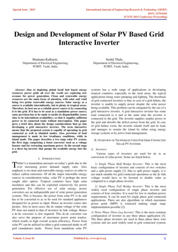
Special Issue - 2015International Journal of Engineering Research & Technology (IJERT)ISSN: 2278-0181ICNTE-2015 Conference Proceedingsat the output of the solar panels to somewhat around 700Vbecause that is approximatedc link voltage for atransformerless grid connected solar pv system, when the gridvoltage is 230 volts. But the dc link voltage is maintained bythe inverter.(1)It follows the simple and time tested perturb and observealgorithm. The boost converter as a system needs significantcompensation to make it a highly stable system. The amountof compensation by a typical PI compensator is not alwayssufficient to stabilise a boost converter system. Hence the typeIII compensator is used so as to satisfy the stabilityrequirement of the boost converter. A precisely tuned type IIIcompensator will stabilise the boost converter system byproviding the necessary compensation.B. Stage 2.The second stage is a three leg inverter for converting the dcoutput of the boost converter to ac so as to make the availablepower compatible to be fed to the grid. It is given in Fig. 2.condition.). Hence the amount of current to be fed into thegrid remains to be regulated and varied according to theavailable power at the output of the boost converter, i.e. stage1. The current flowing to the grid is also sensed and convertedto the dq reference frame. Hence we get the values Id and Iq.These values are compared to the referance values Id* andIq*. For transferring only active power to the grid, thevariable Id needs to be regulated, while, by setting thereference value Iq* to zero, the reactive power is forced tozero. Hence only active power is transferred to the grid. Thereference value Id* is generated using the dc link voltage. Thedifference between Id* and Id, is passed through a PIregulator which acts like a compensator and also eliminateserror. The output of the PI regulator is again converted backto three phase, using the phase angle available from the threephase PLL. This is given to PWM modulator, which fires theswitches of the three leg inverter. The transfer function of athree leg inverter is given below. The equations belowrepresent control to d axis current in grid connected mode. (2)(3)IV. MODES OF OPERATIONThe modes of operation are discussed below in brief.A. Grid connected mode.In this mode, the grid is available. In this mode, the loadshown in Fig. 1 will get uninterruptible power even if verylittle solar power is available, as during cloudy weather orduring the times around sunrise and sunset. In this mode, thesurplus power (if available) is pumped into the grid and, incase of power deficit (when solar power available is lowerthan required by the connected load), the deficit power istaken from the grid.B. Island mode.The system will enter this mode in the event of grid failureand when the solar power available is sufficient to cater to theconnected load.Fig. 2 Functional block diagram of stage 2.For grid synchronisation the, dq reference frame has beenused due to its advantages over other methods [9][10]. Asseen in Fig. 2, the grid voltage is sensed and the grid angle(theta) is obtained by the use of a three phase PLL (PhaseLocked Loop). In the grid connected mode of operation, thevoltage is always determined by the grid. Once the outputvoltage and the phase of the stage 2 perfectly matches to thatof the grid, the switch between the grid and stage 2 is closedto facilitate power flow to the grid (or from the grid in deficitVolume 3, Issue 01C. Load management mode.The system would enter this mode only during the event of agrid failure and when the available solar power won‟t besufficient to feed the connected load. In this mode, theavailable power will then be utilised by managing the variousconnected mode by priority and the amount of power eachload consumes. The frequent occurrence of this mode will bein the monsoons and the applications in places where the gridcondition is poor. Immediately after the system enters thisPublished by, www.ijert.org3
Special Issue - 2015International Journal of Engineering Research & Technology (IJERT)ISSN: 2278-0181ICNTE-2015 Conference Proceedingsmode, there can be a sudden switching of various loadsdepending upon the priority of the load and the available solarinsolation (power).VI. HARDWARE IMPLEMENTATION AND RESULTSV. SIMULATION DETAILSThe system was simulated for island mode of operation i.e. involtage mode control. The system worked stably and accuratesignal tracking was done using standalone mode. PIcompensator was used for stability and error elimination. ForPI controller, Proportional gain (Kp) value was 40 andIntegral gain value (Ki) was 200 for d component as well asfor q component The following results were obtained. Theinverter was also tested for „sudden change in load‟ condition,for which it showed satisfactory performance. The change incontrol signal for sudden change in load can be observed attime 0.2 in Fig. 4 below.Fig. 6 Hardware Implementation.Fig. 3 Inverter Output VoltageFig. 7 Output Voltage Waveforms in standalone mode.VII. CONCLUSIONIt is seen that, in the above system, the available solar poweris used efficiently as compared to a conventional gridconnected system, due to the ability of the grid interactiveinverter to manage load and operate in the island mode aswell. Also, the system will be cheaper and lighter due to theabsence of a bulky transformer. The energy efficiency can befurther improved by incorporating limited energy storageelement, but, at a higher cost. The proposed system is anattractive option to isolated rural communities that do nothave continuous access to a power grid, due to its loadmanagement capability and cheap cost.Fig. 4 Control Voltage of Inverter.REFERENCESFig. 5 Inverter Output CurrentThe originally connected load is 500VA and at 0.2 seconds theload is doubled i.e. 1KVA. The system response is satisfactoryas there is almost zero variation in system output voltage.Volume 3, Issue 01[1] J. M. Shen, H. L. Jou, J. C. Wu, “Novel Transformerless GridConnected Power Converter With Negative Grounding for PhotovoltaicGeneration System,” IEEE Trans. Power Elecron., vol. 27, no. 4, pp.1818-1829, Apr. 2012.[2] Y. Chen and K. M. Smedley, “A Cost-Effective Single-Stage Inverterwith Maximum Power Point Tracking,” IEEE Trans. Power Electron.,vol. 19, no. 5, pp. 1289-1294, Sep. 2004.[3] S. Adhikari, and F. Li, “Coordinated V-f and P-Q Control of SolarPhotovoltaic Generators with MPPT and Battery Storage inMicrogrids,” IEEE Trans. Smart Grid., vol. 5, no. 3, pp. 1270-1281,May. 2014.[4] Y. Chen and K. M. Smedley, “Three-Phase Boost-Type Grid-ConnectedInverter,” IEEE Trans. Power Electron., vol. 23, no. 5, pp. 2301-2309,Sep. 2008.Published by, www.ijert.org4
Special Issue - 2015[5][6][7][8][9][10]International Journal of Engineering Research & Technology (IJERT)ISSN: 2278-0181ICNTE-2015 Conference ProceedingsS. Anand, S. K. Gundlapalli, and B. G. Fernandes, “Transformer-LessGrid Feeding Current Source Inverter for Solar Photovoltaic System,”IEEE Trans. Industrial Electron., vol. 61, no. 10, pp. 5334-5344, Oct.2014.H. J. Chiu, Y. K. Lo, C. Y. Yang, S. J. Cheng, C. M. Huang, C. C.Chuang, M. C. Kuo, Y. M. Huang, Y. B. Jean, and Y. C. Huang, “AModule-Integrated Isolated Solar Micro inverter,” IEEE Trans.Industrial Electron., vol. 60, no. 2, pp. 781-788, Feb. 2013.L. Chen, A. Amirahmadi, Q. Zhang, N. Kutkut, and I. Batarseh,“Design and Implementation of Three-Phase Two-Stage GridConnected Module Integrated Converter,” IEEE Trans Power Electron.,vol. 29, no. 8, pp. 3881-3892, Aug. 2014.J. Lettl, J. Bauer and L. Linhart, “Comparison of Different Filter Typesfor Grid Connected Inverter,” PIERS Proceedings, pp. 1426-1429, Mar.2011.R. Teodorescu, M. Liserre and P. Rodriguez, “Grid converters for PVand Wind power systems,” 2011 John Wiley & Sons, Ltd. ISBN:978-0-470-05751-3A. Yazdani and R. Iravani “Voltage Sourced Converters in powersystems Modeling, Control, and Applications,” IEEE Press and WILEY(JOHN Wiley A Sons, INC)Volume 3, Issue 01Published by, www.ijert.org5
A grid interactive inverter has some load connected to it and at the same time the inverter is connected to the grid. The inverter supplies surplus power to the grid and absorbs the deficit power from the grid. In case of grid failure event, the inverter islands itself and its load, and manages to sustain the island by either using energy .