Transcription
Global LF Series Pure Sine Wave InverterCharger User’s ManualVersion 8.0PICOGLF10W-PICOGLF60W
AIMS Powerwww.aimscorp.netTable of Contents1. Important Safety Information . - 2 1-1. General Safety Precautions . - 2 1-2. Precautions When Working with Batteries . - 2 2. Introduction . - 3 2-1. General Information . - 3 2-2. Application . - 3 2-3. Mechanical Drawing . - 4 2-4. Features . - 6 2-5. Electrical Performance . - 6 2.5.1 Inverter . - 6 2.5.2 AC Charger . - 7 2.5.3 Transfer .- 10 2.5.4 Auto Frequency Adjust .- 10 2.5.5 Power Saver .- 10 2.5.6 Protections .- 13 2.5.7 Remote Control .- 13 2.5.8 LED Indicator .- 15 2.5.7 Remote Control .- 16 2.5.9 Audible Alarm .- 17 2.5.10 FAN Operation .- 17 2.5.11 DIP Switches .- 18 2.5.12 Auto Generator Start .- 19 2.5.13 Other Features .- 19 2.5.14 Automatic Voltage Regulation .- 20 3 Installation .- 21 3.1 Unpacking and Inspection .- 21 3-2. Location .- 22 3-3. DC Wiring .- 22 3-4. AC Wiring .- 25 3-5. Grounding .- 26 3.5.1 Automatic Neutral-to-Ground Connection .- 26 3.5.2 Disabling the Automatic Neutral-to-Ground Connection .- 27 3-6. Install Flange.- 27 4. Troubleshooting Guide .- 29 5. Warranty .- 31 Appendix 1 .- 32 Appendix 2 - Circuit Schematics .- 34 Appendix 3 - Installation Diagram .- 35 --1-
AIMS Powerwww.aimscorp.net1. Important Safety InformationWARNING! Before using the Inverter, you need to read and save the safety instructions.1-1. General Safety Precautions1-1-1. Do not expose the Inverter to rain, snow, spray, bilge or dust. To reduce risk of hazard, do not coveror obstruct the ventilation openings. Do not install the Inverter in a zero-clearance compartment.Overheating may result. Allow at least 12” of clearance around the inverter for air flow. Make sure that theair can circulate freely around the unit. A minimum air flow of 145CFM is required.1-1-2. To avoid risk of fire and electronic shock, make sure that existing wiring is in good electricalcondition and that the wire is not undersized. Do not operate the Inverter with damaged or substandardwiring.1-1-3. This equipment contains components which may produce arcs and/or sparks. To prevent fire and/orexplosion do not install in compartments containing batteries or flammable materials or in a location whichrequire ignition protected equipment. This includes any space containing gasoline-powered machinery, fueltanks, or joints, fittings, or other connection between components of the fuel system.See Warranty for instructions on obtaining service.1-1-4. Do not disassemble the Inverter/Charger. It contains no user-serviceable parts. Attempting to servicethe Inverter/Charger yourself may result in electrical shock or fire. Internal capacitors remain charged afterall power is disconnected.1-1-5. To reduce the risk of electrical shock, disconnect both AC and DC power from the Inverter/Chargerbefore attempting any maintenance or cleaning. Turning off controls will not reduce this riskCAUTION: Equipment damageThe output side of the inverter’s AC wiring should at no time be connected to public power or a generator.This condition is far worse than a short circuit. If the unit survives this condition, it will shut down untilcorrections are made.Installation should ensure that the inverter’s AC output is, at no time, connected to its AC input.1-2. Precautions When Working with Batteries1-2-1. If battery acid contacts skin or clothing immediately wash with soap and water. If acid enters eyesimmediately rinse eyes with running cold water and seek immediate medical attention.1-2-2. Never smoke or allow a sparks or flames in the vicinity of a battery.1-2-3. Do not drop a metal tool on the battery. The resulting spark or short-circuit on the battery will causean explosion.1-2-4. Remove personal metal items such as rings, bracelets, necklaces, and watches when working with abattery. A battery produces a short-circuit current high enough to weld any metal objects and will cause asevere burn.1-2-5. To reduce the risk of injury, charge only deep-cycle lead acid, lead antimony, lead calcium gel cell,absorbed mat, LIFEPO4 lithium or NiCad/NiFe type rechargeable batteries. Other types of batteries mayswell or burst causing personal injury and damage.-2-
AIMS Powerwww.aimscorp.net2. Introduction2-1. General InformationThe Global LF Series Pure Sine Wave Inverter Charger product line is a combination of aninverter and battery charger with an AC auto-transfer switch into one complete system with apeak conversion efficiency of 88%. It is packed with unique features and it is one of the mostadvanced inverter chargers on the market today. It features power factor correction, sophisticatedmulti-stage charging and pure sine wave output with unprecedentedly high surge capability tomeet demanding power needs of inductive loads without damaging the equipment.When utility AC power cuts off (or falls out of acceptable range), the transfer relay is de-energized and theload is automatically transferred to Inverter mode. Once the qualified AC power is restored the relay is reenergized and the load is automatically reconnected to AC bypass mode. The Global LF Series Inverter isequipped with a powerful four stage smart charger and includes an auto generator start feature. Theoverload capacity of the inverter charger products is 300% of continuous output for up to 20 seconds toreliably support tools and equipment.Another important feature is that the inverter can be easily customized to Battery priority via a DIP switch.This helps to extract maximum power from the battery in renewable energy systems such as solar andwind. The Global LF Series Pure Sine Wave Inverter is suitable for renewable energy systems in worktrucks, RV, marine and emergency appliances.To get the most out of the power inverter, it must be operated and maintained properly. Please read theinstructions in this manual before installing and operating.2-2. ApplicationPower tools–circular saws, drills, grinders, sanders, buffers, weed and hedge trimmers, air compressors.Office equipment – computers, printers, monitors, facsimile machines, scanners.Household items – vacuum cleaners, fans, fluorescent and incandescent lights, shavers, sewing machines.Kitchen appliances – coffee makers, blenders, ice markers, toasters.Industrial equipment – metal halide lamp, high – pressure sodium lamp.Home entertainment electronics – television, VCRs, video games, stereos, musical instruments, satelliteequipment.-3-
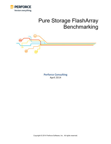
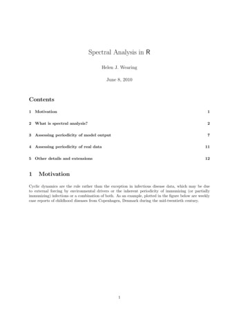
AIMS Powerwww.aimscorp.net2-3. Mechanical DrawingPICOGLF 1-6KW Battery SidePICOGLF 1-1.5KW AC Side-4-
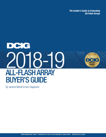
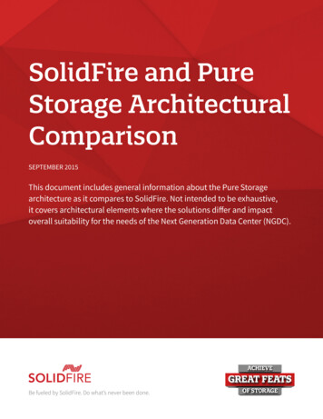
AIMS Powerwww.aimscorp.netPICOGLF 2-3KW AC SidePICOGLF 4-6KW AC Side-5-
AIMS Powerwww.aimscorp.net2-4. FeaturesHigh overload ability up to 300% of rated power (20 sec)Low quiescent current, low power “Power Saving Mode” to conserve energyAutomatic Generator Start4-step intelligent battery charger, PFC (Power Factor Correction) for charger8 pre-set battery type selector switch plus de-sulphation for totally flat batteries Powerful charge rateof up to 105Amp, selectable from 0% 100%10 ms typical transfer time between battery and AC, guarantees powercontinuitySmart LCD remote control (optional)15s delay before transfer when AC resumes, extra protection for loads when used withgeneratorAllows start up and through power with depleted batteries 30A/40A throughput currentabilityMultiple controlled cooling fansExtensive protections against various harsh situations13VDC battery recovery point, dedicated for renewable energy systems2-5. Electrical Performance2.5.1 InverterTopologyThe Global LF inverter/charger is built according to the following topology.Invert: Full Bridge Topology.Charge: Isolated Boost Topology.It works bi-directionally: in one direction it converts DC power from the battery to AC power (InverterMode) and in the other direction it converts external AC power to DC power to charge the batteries (ACMode). The same power components are used in both directions, resulting in high-energy transfer efficiencywith fewer components.Please note that the inverter/charger can only work in one direction at one time (i.e. it cannot work as aninverter and as a charger at the same time).When operating in inverter mode, the direct current (DC) that enters the inverter from the batteries is filteredby a large input capacitor and switched “On” and “Off” by the Metal Oxide Silicon Field Effect Transistors(MOSFET) at a rate of 50 Hz or 60Hz, in this step the DC is converted to low voltage synthesized sine waveAC using an H-bridge configuration and high frequency PWM (Pulse Width Modulation) technique. It isthen directed into the transformer which steps the low AC voltage up to 230 or 120 volts.The unit has a 16bit, 4.9MHZ microprocessor to control the output voltage and frequency as the DC inputvoltage and/or output load varies.Because of high efficiency MOSFETs and the heavy transformers, it outputs PURE SINE WAVE AC withan average THD of 10% (min 3%, max 20% under full linear loads) depending on load connected andbattery voltage. The peak DC to AC conversion efficiency of the Global LF series is 88%.Don’t parallel the AC output of the inverters to increase power capacity as they have nostacking functionality.Overload Capacity-6-
AIMS Powerwww.aimscorp.netThe Global LF series inverters have high overload capacities, making it ideal to handle demanding loads. 1For 110% Load 125%( 10%), no audible alarm for 14 minutes, beeps 0.5s every 1s in the 15th minute,and Fault (Turn off) after the 15th minute.2 For 125% Load 150%( 10%), beeps 0.5s every 1s and Fault (Turn off) after 1 minute. 3For 300% Load 150%( 10%), beeps 0.5s every 1s and Fault (Turn off) after 20s.Caution:After the inverter is switched on, it takes time for it to self-diagnose and ready to deliver full power. Hence,always switch on the load(s) after a few seconds of switching on the inverter. Avoid switching on theinverter with the load already switched on. This may prematurely trigger the overload protection. When aload is switched on, it may require an initial higher power surge to start. Hence, if multiple loads are beingpowered, they should be switched on one by one so that the inverter is not overloaded by the higher startingsurge if all the loads are switched on at once.2.5.2 AC ChargerThe Global LF Series is equipped with an active PFC (Power Factor Corrected) multistage battery charger.The PFC feature is used to control the amount of power used to charge the batteries in order to obtain apower factor as close as possible to 1.Unlike other inverters whose max charging current decreases according to the input AC voltage, GlobalLF series charger is able to output max current as long as the input AC voltage is in the range of 164243VAC(95-127VAC for 120V model), and AC frequency is in the range of 48-54Hz(58-64Hz for 60Hzmodel).The Global LF series inverter has a very rapid charge current available, and the max charge current can beadjusted from 0%-100% via a liner switch to the right of the battery type selector. This will be helpful if youare using our powerful charger on a small capacity battery bank. Fortunately, the liner switch can effectivelyreduce the max charging current to 20% of its peak.Choosing “0” in the battery type selector will disable the charging function.Caution:Turn the charge current control switch gently to avoid breakage due to over-turning.There are 3 charging stages:Bulk Charging: (fast charge LED solid) this is the initial stage of charging. While Bulk Charging, thecharger supplies the battery with controlled constant current. The charger will remain in Bulk charge untilthe Absorption charge voltage (determined by the Battery Type selection) is achieved.A software timer will measure the time from A/C start until the battery charger reaches 0.3V below theboost voltage, then take this time asT0 and T0 10 T1.Absorb Charging:(fast charge LED blinking) This is the second charging stage when the fast charge LEDis flashing and begins after the absorb voltage has been reached. Absorb Charging provides the batterieswith a constant voltage and reduces the DC charging current in order to maintain the absorb voltage setting.In this period, the inverter will start a T1 timer; the charger will keep the boost voltage in Boost CVmode until the T1 timer has run out. Then drop the voltage down to the float voltage. The timer has aminimum time of 1 hour and a maximum time of 12 hours.Float Charging: (float charge LED solid) The third charging stage occurs at the end of the AbsorbCharging time. While Float charging, the charge voltage is reduced to the float charge voltage(determined by the Battery Type selection*). In this stage, the batteries are kept fully charged and ready ifneeded by the inverter.-7-
AIMS Powerwww.aimscorp.netIf the A/C is reconnected or the battery voltage drops below 12Vdc/24Vdc, the charger will restart the abovecycle.If the charge maintains the float state for 10 days, the charger will deliberately reset the cycle to protect thebattery.Battery type selectorSwitch setting0123456789DescriptionCharger OffGel USAAGM 1AGM 2Sealed lead acidGel EUROOpen lead acidLithium batteryDe-sulphationNot usedBoost / VdcFloat / Vdc14.014.114.614.414.414.814.415.5 (4 Hours then Off)13.713.413.713.613.813.814.4For 24V X 2, for 48V X 4. (X multiply)De-sulphationThe de-sulphation cycle (switch position 8) is a very dangerous setting if you do not know what you aredoing. Before attempting to use this cycle you must clearly understand what it does and when and howyou would use it.-8-
AIMS Powerwww.aimscorp.netWhat causes sulphation? This can occur with infrequent use of the batteries or if the batteries have beendischarged low enough that they will not accept a charge. This cycle is a very high voltage charge cycledesigned to try to break down the sulphated crust that is preventing the plates from taking a charge andallowing the plates to clean up and accept a charge once again.Charging depleted batteriesThe Global LF series inverter allows start up and through power with depleted batteries.For 12VDC models: after the battery voltage goes below 10V and the power switch is kept in the "ON"position and the inverter stays connected to the battery and the battery voltage doesn’t drop below 9V, theinverter will be able to charge the battery once qualified AC inputs are present.Before the battery voltage goes below 9VDC, the charging can be activated when the switch is turned to“OFF”, then to “ON”.When the voltage goes below 9VDC, and you accidently turn the switch to OFF or disconnect the inverterfrom the battery, the inverter will not be able to charge the battery once again, because the CPU losesmemory during this process.For 24VDC models: multiply all VDC by 2.For 48VDC models: multiply all VDC by 4.Charging current for each 20VCurrent35 /-5A20 /-5A50 /-5A25 /-5A65 /-5A30 /-5A20 /-5A85 /-5A45 /-5A30 /-5A115 /-5A65 /-5A40 24V120V70 /-5A50 /-5ACurrent35 /-5A15 /-5A50 /-5A25 /-5A70 /-5A30 /-5A20 /-5A100 /-5A35 /-5A30 /-5A115 /-5A50 /-5A40 /-5A150 /-5A75 /-5A60 /-5A85 /-5A85 /-5A60 /-5AThe charging capacity will go to peak charge rate in about 3 seconds. This may cause a generator to dropfrequency, making the inverter transfer to battery mode.It is recommended to gradually put the charging load on the generator by switching the charging switchfrom min to max. Together with the 15s switch delay our inverter gives the generator enough time to spin up.This will depend on the size of the generator and rate of charge. As a general rule, the Bulk Charging-9-
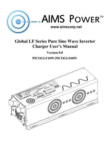
AIMS Powerwww.aimscorp.netCurrent should be limited to 30% of the capacity of the battery bank. Higher charging current may be used ifpermitted by the battery manufacturer.Caution:Please use a small jeweler’s style flat-head screwdriver to turn the charge currentcontrol switch gently to avoid breakage due to over-turning.To guarantee the best performance of AC charger when the AC input is from agenerator, the standby generator should be of at least 150% higher capacity than theinverter.Warning! Operation with an under-rated generator or generator with unqualifiedwave form may cause premature failure which is not under warranty.2.5.3 TransferSwift Power TransferWhile in the Standby Mode, the AC input of the inverter is continually monitored. Whenever AC powerfalls below the low AC voltage trip voltage (90VAC default setting for 120VAC), the inverter automaticallytransfers back to the Invert Mode with minimum power interruption to your appliances - as long as theinverter is turned on. The transfer from Standby mode to Inverter mode occurs in approximately 10milliseconds. And it is even shorter from Inverter mode to Standby mode.This transfer time is usually fast enough to keep your equipment (including computers) powered up, thus ourinverter can be used as a line interactive UPS.Synchronized Power TransferWhen a load is transferred from inverter AC output to another backup AC source of power through thetransfer switch, there will be a finite interruption of power to the load for the transfer to take place. Amismatch of phase and frequency of the inverter AC output and the backup AC source in transfer is likely todamage the backup AC source / a reactive load. With sophisticated circuitry design, our inverter will firstlock on the frequency and phase of the input shore power/generator power and make a smooth and safetransfer at the zero voltage point to minimize the impact on the power modules.Transfer DelayThere is a 15-second delay from the time the inverter senses that continuously qualified AC is present at theinput terminals to when the transfer is made. This delay is built in to provide sufficient time for a generatorto spin-up to a stable voltage and frequency and avoid relay chattering. The inverter will not transfer togenerator until it has locked onto the generator’s output. This delay is also designed to avoid frequentswitching when input utility is unstable.2.5.4 Auto Frequency AdjustThe factory default configuration for inverters sold in American market is 60Hz.If the output frequency needs to be changed this is done by putting in a valid input Power Source to theinverter’s input lines. Once the inverter validates the input, the output will automatically change.NOTE: The inverter will output factory set frequency of 60Hz controlled with DIP switch #4 position.2.5.5 Power SaverThere are 2 different working statuses for our Global LF inverter:“Power On” and “Power Off”.When the power switch is in “Unit Off” position, the inverteris powered off.- 10 -
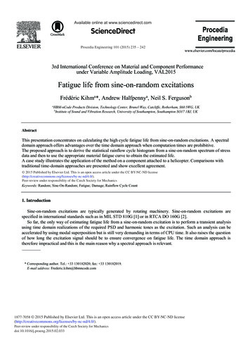
AIMS Powerwww.aimscorp.netWhen the power switch is turned to either of “Power SaverAuto” or “Power Saver Off”, the inverter is powered on.Power saver function is designed to conserve battery powerwhen AC power is not or rarely required by the loads.In this mode, the inverter pulses the AC output looking for anAC load (i.e., electrical appliance). Whenever an AC load (greater than 50 watts) is turned on, the inverterrecognizes the need for power and automatically starts inverting and output goes to full voltage. Whenthere is no load (or less than 50 watts) detected, the inverter automatically goes back into search mode tominimize energy consumption from the battery bank.In “Power saver on” mode, the inverter will draw power mainly in sensing moments, thus theidle consumption is significantly reduced.The inverter will detect a load for 250ms every 3 seconds (DOP switch#3 position 1).Note: The minimum power of a load to take inverter out of sleep mode (Power Saver On) is 50 Watts.The Global LF Series is designed with extremely low idle power consumption which is only a mere 0.81.8% of its rated power.Power saver onPower saver offPower saver on(Load detected)- 11 -
AIMS Powerwww.aimscorp.netGlobal LF Series Idle Power Consumption (in Watts)Model ICOGLF60W48V230VSPower Saver 538.546.5455044.54852.54855.5Power Saver On 526.276.82980.730.3When in the search sense mode, the green power LED will blink and the inverter will make a ticking sound.- 12 -
AIMS Powerwww.aimscorp.netAt full output voltage, the green power LED will light steadily and the inverter will make a steady hummingsound. When the inverter is used as an “uninterruptible” power supply the search sense mode or “PowerSaver On” function should be defeated.ExceptionsSome devices when scanned by the load sensor cannot be detected. Small fluorescent lights and inductiveloads are the most common example. (Try altering the plug polarity by turning the plug over.) Somecomputers and sophisticated electronics have power supplies that do not present a load until line voltage isavailable. When this occurs, each unit waits for the other to begin. To drive these loads either a smallcompanion load must be used to bring the inverter out of its search mode, or the inverter may beprogrammed to remain at full output voltage (Power On mode).2.5.6 ProtectionsThe Global LF series inverter is equipped with extensive protections against various harsh situations/faults.These protections include:AC input over voltage protection/AC input low voltage protectionLow battery alarm/high battery alarmOver temperature protection/over load protectionShort circuit protection (1s after fault)Back feeding protectionWhen over temperature /over load occur, after the fault is cleared, the master switch needs to be resetto restart the inverter.The low battery voltage trip point can be customized from a defaulted value of 10VDC to 10.5VDC thruSW1 on the DIP switch.The inverter will go to over temp protection when the heat sink temp. 105ºC(221 ), and go to fault(shutdown Output) after 30 seconds. The switch needs be reset to activate the inverter.The Global LF series inverter has back feeding protection which avoids presenting an AC voltage on the ACinput terminal in inverter mode.After the reason for the fault is cleared, the inverter needs to be reset to start working.2.5.7 Remote ControlApart from the switch panel on the front (or top) of the inverter, an extra switch panel connected to the RJ11port at the DC side of the inverter thru a standard telephone cable can also control the operation of theinverter (sold separately Part # PICGLFREMOTE).If an extra switch panel is connected to the inverter via “remote control port”, together with the panel onthe inverter case, the two panels will be connected and operated in parallel.Whichever first switches from “Off” to “Power saver off” or “Power saver on”, it will power the inverteron. If the commands from the two panels conflict, the inverter will operate according to the followingpriority: Power saver on Power saver off Power offOnly when both panels are turned to the “Unit Off” position, will the inverter be powered off.The max length of the cable is 60 feet.- 13 -
AIMS Powerwww.aimscorp.netThe Remote LCD will display the following content:Function DescriptionThe LCD remote control panel will display the operation status of the inverter, including:Input AC VoltageOutput AC VoltageBattery VoltageOutput FrequencyOutput LoadWork ModeAlarm FaultBattery CapacityA push button on the left of the panel can be used to turn off the LCD screen and save 0.1A current draw onthe battery.Greeting message of “Welcome to AIMS POWER”AC Status & Input Voltage“AC: abnormal” is displayed when AC input is not qualified.Output Voltage/Frequency and Output Current (in percentage) in invertermode Battery volta
Before using the Inverter, you need to read and save the safety instructions. 1-1. General Safety Precautions 1-1-1. Do not expose the Inverter to rain, snow, spray, bilge or dust. To reduce risk of hazard, do not cover or obstruct the ventilation openings. Do not install the Inverter in a zero-clearance compartment. Overheating may result.