Transcription
Power Xpert Solar 1500/1670 kW InverterUtility-Scale Photovoltaic InverterInstallation and OperationUser ManualEffective October 2014New Information
Power Xpert Solar 1500/1670 kW InverterDisclaimer of Warranties and Limitation of LiabilityThe information, recommendations, descriptions and safety notations in this document arebased on Eaton Corporation’s (“Eaton’s”) experience and judgment and may not cover allcontingencies. If further information is required, an Eaton sales office should be consulted.Sale of the product shown in this literature is subject to the terms and conditions outlined inappropriate Eaton selling policies or other contractual agreement between Eaton and thepurchaser.THERE ARE NO UNDERSTANDINGS, AGREEMENTS, WARRANTIES, EXPRESSED ORIMPLIED, INCLUDING WARRANTIES OF FITNESS FOR A PARTICULAR PURPOSE ORMERCHANTABILITY, OTHER THAN THOSE SPECIFICALLY SET OUT IN ANY EXISTINGCONTRACT BETWEEN THE PARTIES. ANY SUCH CONTRACT STATES THE ENTIREOBLIGATION OF EATON. THE CONTENTS OF THIS DOCUMENT SHALL NOT BECOMEPART OF OR MODIFY ANY CONTRACT BETWEEN THE PARTIES.In no event will Eaton be responsible to the purchaser or user in contract, in tort (includingnegligence), strict liability or otherwise for any special, indirect, incidental or consequentialdamage or loss whatsoever, including but not limited to damage or loss of use of equipment,plant or power system, cost of capital, loss of power, additional expenses in the use ofexisting power facilities, or claims against the purchaser or user by its customers resultingfrom the use of the information, recommendations and descriptions contained herein. Theinformation contained in this manual is subject to change without notice.Cover Photo: Power Xpert Solar 1500/1670 kW InverterPower Xpert Solar 1500/1670 kW InverterMN141001EN—October 2014www.eaton.comi
Power Xpert Solar 1500/1670 kW InverterScope of the ManualTarget AudienceThis manual describes the installation, operation, and maintenance of the Eaton Power XpertSolar 1500/1670 kW Inverters. This manual is intended for professionals working in thephotovoltaic industry. The information provided will enable Architects, Consultants,Contractors, Engineers, Solar Integrators, and Utilities to successfully specify, order,design-in, install, commission, operate, and maintain the inverter.This equipment, its installation, operation, and maintenance is intended for qualifiedpersonnel who are licensed and trained for electrical-power systems ranging to 35 kV voltsAC, and 1000 volts DC. This manual addresses the inverter specific input DC and outputAC voltages.Product UsageEaton Power Xpert Solar 1500/1670 kW Inverter is intended for conversion ofphotovoltaic-module energy into alternating-current for grid-tie applications. Usageother than as intended is prohibited, voiding the warranty and certification.iiPower Xpert Solar 1500/1670 kW Inverter MN141001EN—October 2014www.eaton.com
Power Xpert Solar 1500/1670 kW InverterSupport ServicesThe goal of Eaton is to ensure your greatest possible satisfaction with the operation of ourproducts. We are dedicated to providing fast, friendly, and accurate assistance. That is whywe offer you so many ways to get the support you need. Whether it’s by phone, fax, or email,you can access Eaton’s support information 24 hours a day, seven days a week. Our widerange of services is listed below.Please contact your local distributor or sales representative for product specification,availability pricing, and ordering. Product-application assistance is available through thesechannels.WebsiteUse the Eaton website to find product information, directly. You can also find information onlocal distributors or Eaton’s sales offices.Product Websitewww.eaton.com/powerxpertsolar Photovoltaic Inverterswww.eaton.com/solar Photovoltaic Balance of System ProductsEatonCare Customer Support CenterCall the EatonCare Support Center if you need assistance with placing an order, stockavailability or proof of shipment, expediting an existing order, emergency shipments, productprice information, returns other than warranty returns, and information on local distributors orsales offices.Voice: 855-ETN-SOLR (386-7657)(8:00 a.m.–6:00 p.m. EST)FAX: 800-752-8602After-Hours Emergency: 800-543-7038(6:00 p.m.–8:00 a.m. EST)Technical Resource CenterVoice: 877-ETN-CARE (386-2273)(8:00 a.m.–5:00 p.m. EST)FAX: 828-651-0549email: TRC@eaton.comPhotovoltaic-Inverter Specific Contact InformationEaton901 S 12th StreetWatertown, WI 53094United StatesPower Xpert Solar 1500/1670 kW InverterMN141001EN—October 2014www.eaton.comiii
Power Xpert Solar 1500/1670 kW InverterTable of ContentsDEFINITIONS, SAFETY, AND LIMITATIONSRead these Instructions FIRST . . . . . . . . . . . . . . . . . . . . . . . . . . . . . . . . . . . . .Save These Instructions . . . . . . . . . . . . . . . . . . . . . . . . . . . . . . . . . . . . . . . . . .Definitions and Symbols . . . . . . . . . . . . . . . . . . . . . . . . . . . . . . . . . . . . . . . . . .Safety Procedures . . . . . . . . . . . . . . . . . . . . . . . . . . . . . . . . . . . . . . . . . . . . . . .Limitations . . . . . . . . . . . . . . . . . . . . . . . . . . . . . . . . . . . . . . . . . . . . . . . . . . . . .11124POWER XPERT SOLAR 1500/1670 KW INVERTERProduct Description . . . . . . . . . . . . . . . . . . . . . . . . . . . . . . . . . . . . . . . . . . . . . .Product Information and Labeling . . . . . . . . . . . . . . . . . . . . . . . . . . . . . . . . . . .Inverter Overview and Highlights . . . . . . . . . . . . . . . . . . . . . . . . . . . . . . . . . . .Major Components and Functionality . . . . . . . . . . . . . . . . . . . . . . . . . . . . . . . .5568INSTALLATION INSTRUCTIONSDelivery Inspection . . . . . . . . . . . . . . . . . . . . . . . . . . . . . . . . . . . . . . . . . . . . . .Unloading and Moving Procedure . . . . . . . . . . . . . . . . . . . . . . . . . . . . . . . . . . .Dimensions and Weight . . . . . . . . . . . . . . . . . . . . . . . . . . . . . . . . . . . . . . . . . .Clearance Requirements . . . . . . . . . . . . . . . . . . . . . . . . . . . . . . . . . . . . . . . . . .Ventilation . . . . . . . . . . . . . . . . . . . . . . . . . . . . . . . . . . . . . . . . . . . . . . . . . . . . .Anchoring Requirements—Concrete Pad and Seismic . . . . . . . . . . . . . . . . . . .DC Input Fuse Options—Re-Combiner . . . . . . . . . . . . . . . . . . . . . . . . . . . . . . .13131415161617ELECTRICAL CONNECTIONSElectrical Connections . . . . . . . . . . . . . . . . . . . . . . . . . . . . . . . . . . . . . . . . . . . .DC Circuit Connection . . . . . . . . . . . . . . . . . . . . . . . . . . . . . . . . . . . . . . . . . . . .Inverter AC Connection . . . . . . . . . . . . . . . . . . . . . . . . . . . . . . . . . . . . . . . . . . .Neutral and Equipment Ground . . . . . . . . . . . . . . . . . . . . . . . . . . . . . . . . . . . . .Phase Rotation . . . . . . . . . . . . . . . . . . . . . . . . . . . . . . . . . . . . . . . . . . . . . . . . .Grounding Conductors . . . . . . . . . . . . . . . . . . . . . . . . . . . . . . . . . . . . . . . . . . . .Grounding Electrode Terminal and Conductor . . . . . . . . . . . . . . . . . . . . . . . . . .Positive-Ground Photovoltaic Configuration . . . . . . . . . . . . . . . . . . . . . . . . . . .Grounding . . . . . . . . . . . . . . . . . . . . . . . . . . . . . . . . . . . . . . . . . . . . . . . . . . . . .192122232324252626INVERTER OPERATIONPre-Commission Check . . . . . . . . . . . . . . . . . . . . . . . . . . . . . . . . . . . . . . . . . . .Energize and Operation Procedure: Automatic Operation . . . . . . . . . . . . . . . . .De-Energize Procedure . . . . . . . . . . . . . . . . . . . . . . . . . . . . . . . . . . . . . . . . . . .Interactive Menu . . . . . . . . . . . . . . . . . . . . . . . . . . . . . . . . . . . . . . . . . . . . . . . .Operational States . . . . . . . . . . . . . . . . . . . . . . . . . . . . . . . . . . . . . . . . . . . . . . .2930333436MAINTENANCEMaintenance Schedule . . . . . . . . . . . . . . . . . . . . . . . . . . . . . . . . . . . . . . . . . . .40TROUBLESHOOTINGIdentifying Inverter Faults and Warnings . . . . . . . . . . . . . . . . . . . . . . . . . . . . . .Inverter Response to Faults and Warnings . . . . . . . . . . . . . . . . . . . . . . . . . . . .Troubleshooting Ground-Faults . . . . . . . . . . . . . . . . . . . . . . . . . . . . . . . . . . . . .ivPower Xpert Solar 1500/1670 kW Inverter MN141001EN—October 2014www.eaton.com434356
Power Xpert Solar 1500/1670 kW InverterTable of Contents, continuedGLOSSARYGlossary . . . . . . . . . . . . . . . . . . . . . . . . . . . . . . . . . . . . . . . . . . . . . . . . . . . . . . .60APPENDIX APower Xpert Solar Electrical, Mechanical and Equipment Specifications . . . . .65APPENDIX BFlex Bus Kit: Throat Connection . . . . . . . . . . . . . . . . . . . . . . . . . . . . . . . . . . . . .68APPENDIX CStep-Up Transformer Sensor Signals . . . . . . . . . . . . . . . . . . . . . . . . . . . . . . . . .70APPENDIX DTorque Values . . . . . . . . . . . . . . . . . . . . . . . . . . . . . . . . . . . . . . . . . . . . . . . . . .71APPENDIX EFuse Replacement . . . . . . . . . . . . . . . . . . . . . . . . . . . . . . . . . . . . . . . . . . . . . . .72APPENDIX FEnclosure Lifting Instructions . . . . . . . . . . . . . . . . . . . . . . . . . . . . . . . . . . . . . . .75APPENDIX GCustomer External Load-Power Circuit Breaker . . . . . . . . . . . . . . . . . . . . . . . . .76APPENDIX HMaintenance Schedule Record . . . . . . . . . . . . . . . . . . . . . . . . . . . . . . . . . . . . .77APPENDIX JNotes . . . . . . . . . . . . . . . . . . . . . . . . . . . . . . . . . . . . . . . . . . . . . . . . . . . . . . . . .Power Xpert Solar 1500/1670 kW Inverter78MN141001EN—October 2014www.eaton.comv
Power Xpert Solar 1500/1670 kW InverterList of FiguresFigure 1. Symbols and Descriptions . . . . . . . . . . . . . . . . . . . . . . . . . . . . . . . . . . . . . . . .Figure 2. DANGER—WARNING—CAUTION—NOTICE . . . . . . . . . . . . . . . . . . . . . . . . .Figure 3. Power Xpert Solar Inverter Rating Label (Typical) . . . . . . . . . . . . . . . . . . . . . .Figure 4. Power Xpert Solar 1500/1670 kW Inverter Diagram . . . . . . . . . . . . . . . . . . . .Figure 5. Major Components Diagram: Inverter and Step-Up Transformer . . . . . . . . . .Figure 6. Power Xpert Solar Inverter with Step-Up Transformer . . . . . . . . . . . . . . . . . .Figure 7. Power Xpert Solar: Inverter Power Module and Power Stacks . . . . . . . . . . . .Figure 8. Schematic of the Ventilation-Principle . . . . . . . . . . . . . . . . . . . . . . . . . . . . . . .Figure 9. Mounting of Lifting Brackets . . . . . . . . . . . . . . . . . . . . . . . . . . . . . . . . . . . . . .Figure 10. Mounting of Cover Plates . . . . . . . . . . . . . . . . . . . . . . . . . . . . . . . . . . . . . . .Figure 11. Inverter Transport by Lift Truck . . . . . . . . . . . . . . . . . . . . . . . . . . . . . . . . . . . .Figure 12. Inverter Transport by Crane . . . . . . . . . . . . . . . . . . . . . . . . . . . . . . . . . . . . . .Figure 13. Inverter Cabinet Locations . . . . . . . . . . . . . . . . . . . . . . . . . . . . . . . . . . . . . .Figure 14. Anchoring Requirements . . . . . . . . . . . . . . . . . . . . . . . . . . . . . . . . . . . . . . .Figure 15. Inverter Conductor Entry-Routing . . . . . . . . . . . . . . . . . . . . . . . . . . . . . . . . .Figure 16. Inverter and Transformer Conductor Entry Locations . . . . . . . . . . . . . . . . . .Figure 17. Electrical Connections, Power Xpert Solar 1500/1670 kW Inverter . . . . . . . .Figure 18. PV Conductor Terminations (Typical)—Positive and Negative Connections .Figure 19. Typical Mounting with MV Transformer . . . . . . . . . . . . . . . . . . . . . . . . . . . .Figure 20. Phase Locations . . . . . . . . . . . . . . . . . . . . . . . . . . . . . . . . . . . . . . . . . . . . . .Figure 21. AC Output Phase Connections: Throat Connection Details . . . . . . . . . . . . .Figure 22. DC Section: 24 Input-Circuit options, Illustrated PV Input Connections . . . .Figure 23. DC Section Grounding Bus and Grounding Electrode Terminal . . . . . . . . . .Figure 24. AC Section Equipment Grounding Bus . . . . . . . . . . . . . . . . . . . . . . . . . . . . .Figure 25. Accessory Power Location . . . . . . . . . . . . . . . . . . . . . . . . . . . . . . . . . . . . . .Figure 26. Inverter AC Cabinet Section . . . . . . . . . . . . . . . . . . . . . . . . . . . . . . . . . . . . .Figure 27. HMI Menu Display Navigation . . . . . . . . . . . . . . . . . . . . . . . . . . . . . . . . . . . .Figure 28. Power Xpert Solar Machine-State Transition Diagram . . . . . . . . . . . . . . . . .Figure 29. The GFDI Connection Points . . . . . . . . . . . . . . . . . . . . . . . . . . . . . . . . . . . . .Figure 30. Flex Bus Kit: 84-37413-1 . . . . . . . . . . . . . . . . . . . . . . . . . . . . . . . . . . . . . . . .Figure 31. Example of Available Step-Up Transformer Monitoring . . . . . . . . . . . . . . . . .Figure 32. Enclosure Lifting Instructions . . . . . . . . . . . . . . . . . . . . . . . . . . . . . . . . . . . .Figure 33. Location of CB4 in the Electrical Path . . . . . . . . . . . . . . . . . . . . . . . . . . . . . .viPower Xpert Solar 1500/1670 kW Inverter MN141001EN—October 424262627272835465969707576
Power Xpert Solar 1500/1670 kW InverterList of TablesTable 1. Word Meanings: “shall,” “may,” “must,” and “should” . . . . . . . . . . . . . . . . . .Table 2. Standard Inverter Features . . . . . . . . . . . . . . . . . . . . . . . . . . . . . . . . . . . . . . . .Table 3. DC Input Fuse Re-Combiner Options:Power Xpert Solar 1500/1670 kW Inverter . . . . . . . . . . . . . . . . . . . . . . . . . . . . . . .Table 4. Mounting . . . . . . . . . . . . . . . . . . . . . . . . . . . . . . . . . . . . . . . . . . . . . . . . . . . . .Table 5. Inverter Minimum and Required Clearances . . . . . . . . . . . . . . . . . . . . . . . . . .Table 6. Re-Combiner Input Options: Power Xpert Solar 1500/1670 kW Inverter . . . . .Table 7. Fasteners and Sequence for Conductor Termination . . . . . . . . . . . . . . . . . . . . .Table 8. 3-Wire Connection—Inverter Point-of-Common Coupling Interface . . . . . . . . .Table 9. 30-Day, 6-Month and Annual Inspection and Maintenance . . . . . . . . . . . . . . .Table 10. Fault and Warning Types: Actions and Resolution . . . . . . . . . . . . . . . . . . . . . .Table 11. Critical Faults: CRITICAL FAULTS . . . . . . . . . . . . . . . . . . . . . . . . . . . . . . . . . . .Table 12. Non-Critical Faults: FAULT . . . . . . . . . . . . . . . . . . . . . . . . . . . . . . . . . . . . . . . .Table 13. Warnings That Become Faults: WARNING R FAULT . . . . . . . . . . . . . . . . . . .Table 14. Warnings That Cannot Become Faults: FAULT R . . . . . . . . . . . . . . . . . . . . .Table 16. Inverter Inhibit Status: INHIBIT . . . . . . . . . . . . . . . . . . . . . . . . . . . . . . . . . . . .Table 15. Alerts That Signal Inverter Service Is Required: NOTIFY . . . . . . . . . . . . . . . .Table 17. Power Xpert Solar Electrical,Mechanical and Equipment Specifications . . . . . . . . . . . . . . . . . . . . . . . . . . . . . . .Table 18. Grid-Tie Settings: Protection Relay . . . . . . . . . . . . . . . . . . . . . . . . . . . . . . . . .Table 19. Step-Up Transformer Sensor Signals . . . . . . . . . . . . . . . . . . . . . . . . . . . . . . .Table 20. DC Section Electrical Connection Torque Values . . . . . . . . . . . . . . . . . . . . . .Table 21. AC Section Electrical Connection Torque Values . . . . . . . . . . . . . . . . . . . . . . .Table 22. Ground Connections . . . . . . . . . . . . . . . . . . . . . . . . . . . . . . . . . . . . . . . . . . . .Table 23. Inverter Fuses . . . . . . . . . . . . . . . . . . . . . . . . . . . . . . . . . . . . . . . . . . . . . . . . .Table 24. Maintenance Schedule Record . . . . . . . . . . . . . . . . . . . . . . . . . . . . . . . . . . . .Power Xpert Solar 1500/1670 kW 7277MN141001EN—October 2014www.eaton.comvii
Power Xpert Solar 1500/1670 kW InverterviiiPower Xpert Solar 1500/1670 kW Inverter MN141001EN—October 2014www.eaton.com
Definitions, Safety, and LimitationsDefinitions, Safety, and LimitationsRead these Instructions FIRSTDANGER of Electric Shock HazardRead this manual thoroughly and make sure the proceduresare understood before attempting to receive, install,commission, operate, or maintain the inverter.DANGER of Electric Shock Hazard indicatesa hazardous situation that, if not avoided,will result in death or serious injury.Do not attempt to receive, install, operate, or maintain thisequipment without proper training, tools, and safetyequipment.When this symbol appears in this document oris posted on/in the inverter equipment, readand follow the instructions carefully.WARNING!Save These InstructionsWARNING indicates a hazardous situation that,if not avoided, could result in death or seriousinjury.SAVE THESE INSTRUCTIONS—This manual containsimportant instructions for the Power Xpert Solar 1500/1670 kW Inverters that shall be followed during all aspectsof planning, designing-in, ordering, receiving, installing,operating, and maintaining the inverter.When this symbol appears in this document oris posted in/on the inverter equipment, readand follow the instructions carefully.Definitions and SymbolsCAUTION!Nomenclature and GlossaryCAUTION indicates a hazardous situation that,if not avoided, could result in moderate orminor injury.In this document, the Power Xpert Solar 1500/1670 kWInverter is referred to as Power Xpert Solar or the Inverter.When this symbol appears in this document oris posted in/on the inverter equipment, readand follow the instructions carefully.A glossary covering many of the terms applicable to theunderstanding and operation of these grid-tie photovoltaic(PV) inverters is included. The glossary defines terms usedwithin this document and applicable to photovoltaic-inverterapplications and photovoltaic systems.NOTICE!NOTICE indicates a situation that, if notavoided, can result in property orequipment damage.DANGER, WARNING, CAUTION, and NOTICEThrough this document and the inverter itself, thewording and use of the symbols; Danger, Danger ofElectric Shock Hazard; Warning!; Caution!; and Notices!have specific meanings and precede task-descriptions incompliance with the NEC , OSHA, NFPA-70E , andindustry practice. While repetitive in nature, they alert ofthe potential personal and physical dangers associatedwith equipment. The specific text accompanies each ofthe specific symbols.DANGER is used when an accident will happen and theresult will be death or serious injury.When this symbol appears in this document oris posted in/on the inverter equipment, readand follow the instructions carefully.shall—may—must—shouldThese words derive from various sources including theCode of Federal Regulations (USA), Title 29, Part 1910,NFPA Standard 70E-2009/11 Edition and Eaton policydocuments. When used in this document their meaningsare as follows:WARNING is used when an accident could happen andthe probability of death or serious injury.Table 1. Word Meanings: “shall,” “may,” “must,”and “should”CAUTION is used when an accident could happen andthe result will be moderate or minor injury.Word“shall”Law mandates the action (OSHA)NOTICE is used when an accident could result inproperty or equipment damage.“may”Almost always mandated, some limited exceptions (OSHA)“must”Recommended policy, need to have very good reasons todisregard (Eaton policy documents)“should”Recommended practice under normal circumstances (OSHA)Power Xpert Solar 1500/1670 kW InverterMeaningMN141001EN—October 2014www.eaton.com1
Definitions, Safety, and LimitationsSymbolsDefinition of the symbols used within this document andinverter.Figure 1. Symbols and DescriptionsSymbolDescriptionDirect currentAlternating current- sinusoidal waveform Phase symbol for ACelectricityØUsed to identify field-wiringEquipment GroundingConductor (EGC)-- or “-”- or “ ”Used for identifying pointswithin equipment that areintended to be bounded toearth ground (e.g., GET).ONOFFNegative PVPositive PVSafety ProceduresPersonal SafetyWhen installing or maintaining the Power Xpert Solarinverter, there are exposed components with housings orprotrusions at or above utility and photovoltaic voltagepotentials. Extreme care shall be taken to protect againstelectric shock and arc-flash hazards by de-energizing andisolating all sources of connected and stored energyBEFORE attempting to install or perform work on/inside thePower Xpert Solar.Verify all equipment and tools are properly grounded. Standon an insulating pad and make it a habit to use only the righthand when checking components. Always work with anotherperson in case an emergency occurs.2Wear appropriate electrical personal protective equipment(PPE), including safety glasses and hearing protectionwhenever working on this equipment and while operatingrotating or moving machinery during installation orperforming maintenance or service.Disconnect all sources of power prior to accessing anyportion of the inverter following OSHA and NFPA-70Eelectric-shock and arc-flash safety procedures.All Danger, Danger of Electric Shock Hazard; Warning!;Caution!; and Notices! alerts must be followed for the properand warranted use of the inverter.Equipment SafetyThe inverter shall be installed in accordance with allapplicable codes and regulations. Consult the latest editionof NFPA 70: National Electrical Code . The installer andoperator shall comply with Code, building, fire marshal, andseismic standards and with NFPA 70E. Utility interconnectapproval is required before installation and operation of thismedium voltage grid-tie photovoltaic inverter.Canadian installations shall follow the NEC 690 andapplicable Canadian Standards Association (CSA), CanadianElectrical Code (CE Code), and the National Building Code ofCanada (NBC). Consult all local and utility regulations for solarphotovoltaic.Non-Code compliant installations will adversely affect thesafe usage and serviceability of the inverter, includingapplicable balance-of-system products, including thephotovoltaic modules. Use only modules specific forgrounded PV systems.The inverter is designed and certified to meet the NEC,OSHA, and NFPA-70E standards and installation methods.These shall take precedence over non-USA centricregulations.Lock Out Tag Out (LOTO)When installing or maintaining the inverter, Lock Out and TagOut (LOTO) all Photovoltaic and Grid (utility) disconnectsbefore working on the equipment.A LOTO policy must be in place when working on theinverter and solar site.Power Xpert Solar 1500/1670 kW Inverter MN141001EN—October 2014www.eaton.com
Definitions, Safety, and LimitationsDe-Energizing the InverterDe-Energizing the Inverter ProcedureThe Power Xpert Solar 1500/1670 kW Inverter is designed tobe connected to photovoltaic DC energy and export ACenergy. It stores a significant amount of capacitanceelectrical energy.1.Turn the ON/OFF function on the HMI (LCD) to the OFFposition.2.The inverter will de-energize when the ON/OFF functionon the HMI is turned OFF and CB1, CB2, CB4, DS1,DS2, DS3, and pre-charge fuses are verified to be in theirrespective opened (disconnected) state.The Inverter Must Be Considered EnergizedWhenever: The medium voltage transformer is energized from theutility. The inverter’s main output circuit breaker CB1 is closed. The inverter’s control-power circuit breaker CB2 is closed. Any of the PV System’s external (to the inverter)disconnects are closed. 3.Closed (ON) means the switching-device contact(s)’ areengaged and able to transfer energy: Voltage or Current.AC and DC Disconnecting Means: The inverter does not provide a means to isolate utilityvoltage on the transformer-side of circuit breaker CB1, CB2or CB4, which are located inside the inverter AC cabinet(section) outer door panel. The medium voltage transformer, unless de-energizedfrom the utility (or through optional switches andbreakers on the medium voltage side) will remainenergized, including the low voltage side connected tothe inverter output phases. 4.All PV systems vary, therefore it is the responsibility ofthe site operator/owner to ensure de-energizingprocedures of the transformer are defined and followed.Wait at least 5 minutes to allow the stored capacitiveenergy to dissipate before opening the inverter cabinetdoors and access panels. Using the appropriate PPE, verify all capacitive voltagehas discharged before servicing the inverter or removingany protective guards to access fuses, terminals, andinverter components. Beware of any additional non-inverter components,circuits, devices, and sources of stored or connectedelectrical energy that may have been added to theinverter or the photovoltaic-site, beyond the scope ofthis manual.The AC bus will be energized whenever the MVtransformer is energized.The inverter does not provide a means to isolateinput-circuits from the PV system’s side of disconnectsDS1, DS2, and DS3, nor the inverter’s pre-charge fuseslocated inside the doors of the inverter DC cabinet(section).Pressing the emergency stop switch (E-stop) willshut-off the inverter, forcing open CB1, DS1, DS2, andDS3, but not the pre-charge fuses, CB2 or CB4.The DC Cabinet Section will be energized wheneverexternal PV-disconnects are closed (electricallyconnected to the inverter)Power Xpert Solar 1500/1670 kW InverterMN141001EN—October 2014www.eaton.com3
Definitions, Safety, and LimitationsPhotovoltaic Ground-FaultThe inverter is designed for grounded PV systems only. Itis furnished with photovoltaic Ground-Fault Detection andInterruption (GFDI). If the inverter detects a PV Ground Fault,it will interrupt the fault-current within the inverter, set aground-fault alarm error message visual on the HMI (LCD)and Modbus, stop exporting power (turn-off) and open CB1,DS1, DS2, and DS3. Additional corrective and protectiveactions will be required when this alarm is active. Refer to“Troubleshooting Ground Faults” on Page 43 for a detaileddescription of the ground fault detection and interruptioncircuit: operation and servicing requirements.By Code, the PV system must be labeled as illustrated,below. Look for such labeling.Figure 2. DANGER—WARNING—CAUTION—NOTICEDANGER ofElectric ShockHazardWARNING!Indicates aHazardousSituationCAUTION!Indicates aHazardousSituationNOTICE!Situation that canResult in Property orEquipment DamageIF A GROUND FAULT IS INDICATED, NORMALLYGROUNDED CONDUCTORS MAY BE UNGROUNDEDAND ENERGIZED.LimitationsThe Power Xpert Solar 1500/1670 kW Inverter is designedand tested to the UL508C and UL 1741 standards. As with allelectrical/electronic equipment, this document cannotpossibility anticipate all site, installation, or operationvariances. It is the system engineer’s, installer’s, operator’sand owner’s responsibility to follow these instructions andensure any deviation from this document first establishesthat neither personnel (persons) safety nor the inverter’s andphotovoltaic (PV) system’s balance of system (BOS)components are compromised.Professional engineering and construction standards mustalways be followed. Incorrect installation and maintenancewill adversely affect any warranty. Contact Eaton for anyquestions.4Power Xpert Solar 1500/1670 kW Inverter MN141001EN—October 2014www.eaton.com
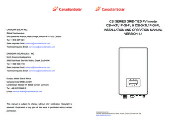
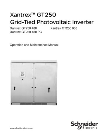
Power Xpert Solar 1500/1670 kW InverterPower Xpert Solar 1500/1670 kW InverterProduct DescriptionProduct Information and LabelingThe Power Xpert Solar 1500/1670 kW Inverter is designedfor commercial and utility-scale photovoltaic systems.Engineered for ease-of-installation, operation andmaintenance, the inverter contains the intelligence tofacilitate the commissioning, operation and shut-downprocedures. The inverter is based upon proprietary Eatontechnology, algorithms, and software.Complete inverter specifications are listed in Appendix A.The Power Xpert Solar 1500/1670 kW Inverter is designedspecifically for North American, 60-Hertz, 3-phase grid tieapplications and 1000 Vdc (array Voc) photovoltaic modulesand systems. The medium voltage level must be definedwhen ordering.The most up-to-date inverter information and documentationis available on the internet.Navigate to: www.eaton.com/PowerXpertSolarOn the front of the inverter, near the Rating Label is the unitgeneral order number (GO#) and the serial number. Pleaseuse this identification when contacting Eaton regarding yourinverter.The Rating label attached to the inverter will be specific tothe unit and its assembly location (i.e., USA or Canada).Figure 3. Power Xpert Solar Inverter Rating Label(Typical) Power Xpert Solar1500 kW InverterMaximum Continuous Output Power AC (kW)Maximum Input Voltage Open Circuit, (Vdc)Maximum DC Input Operating Range (Vdc)Maximum Peak Power Tracking Range, MPPT, (Vdc)Nominal Output Current AC (A)Maximum Branch Circuit Over Protection AC (A)Nominal DC Operating Current DC (A)Maximum Array Short Circuit Current DC (A)Nominal Operating Voltage (Vac)Operating Voltage Range (Vac)Nominal Operating Frequency (Hz)Enclosure RatingOperating Temperature Range ( C)Power Factor (Leading-Lagging)Model No: Power Xpert Solar 150015001000500 - 1000500 - 100027003200310056003-Ø, 320288 to 35260UL Type 3R-20 to 500.91 - 1.0Conforms to UL STD 1741Certified to CSA C22.2 No. 107.1-01Eaton CorporationElectrical Sector877-ETN-CARE (877-386-2273)30-46871-02Power Xpert Solar 1500/1670 kW Inverter4003986PHOTOVOLTAIC UTIILITY INTERACTIVE INVERTERMN141001EN—October 2014www.eaton.com5
Power Xpert Solar 1500/1670 kW InverterInverter Overview and HighlightsThe Power Xpert Solar 1500/1670 kW Inverter is acentral-type photovoltaic inverter designed specifically forgrid-tie utility applications employing photovoltaic
Inverter is referred to as Power Xpert Solar or the Inverter. A glossary covering many of the terms applicable to the understanding and operation of these grid-tie photovoltaic (PV) inverters is included. The glossary defines terms used within this document and applicable to photovoltaic-inverter applications and photovoltaic systems.

![Welcome [s3-ap-southeast-2.amazonaws ]](/img/28/wmi5140-user-manual.jpg)