Transcription
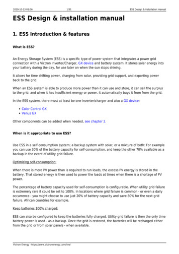
PV Grid Tie InverterSolis Mini Single Phase InverterInstallation and Operation ManualNingbo Ginlong Technologies Co., Ltd.No. 57 Jintong Road, Binhai Industrial Park,Xiangshan, Ningbo, Zhejiang, 315712, P.R.ChinaTel: 86 (0)574 6578 1806Fax: 86 (0)574 6578 1606Email: info@ginlong.comWeb: www.ginlong.comPlease record the serial number of your inverter and quote this when you contact us.C2014, Ningbo Ginlong Technologies Co., Ltd.Ver 1.7
Contents 31.1 Product Descriptions 31.2 Packaging 4 5 51. Introduction2. Safety Instructions2.1 Safety Symbols 52.3 Notice For Use 6 72.2 General Safety Instructions3. Overview3.1 Front Panel Display 7 7 8 8 9 94.2 Mounting the Inverter 10 11 185.1 Start the Inverter 185.2 Stop the Inverter 183.2 LED Status Indicator Lights3.3 Keypad3.4 LCD4. Installation4.1 Select Location for the Inverter4.3 Electrical Connections5. Start & Stop.1.
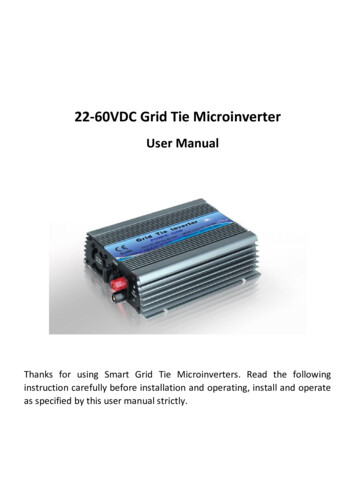
Contents1. Introduction 196.1 Main Menu 196.2 Information 19 21 21 21 226. Operation6.3 Settings6.3.1 Set Time6.3.2 Set Address6.4 Advanced Info.6.4.1 Alarm Message 22 226.4.3 Standard No. 23 23 23 23 24 25 26 26 286.4.2 Temperature6.4.4 Version6.4.5 Communication Data6.5 Advanced Settings6.5.1 Select Standard6.5.2 Grid ON/OFF7. Maintenance8. Trouble Shooting9. Specifications1.1 Product DescriptionsSolis mini single phase series inverters can transfer DC power from PV panels into ACpower and feed into grid. The series inverters contain 5 models which are listed below:For 208 240V grid: Solis-mini-700 Solis-mini-1000 Solis-mini-1500Solis-mini-2000 Solis-mini-2500For 100 127V grid: Solis-mini-700-LV Solis-mini-1000-LVFigure 1.1 Front side viewDC switch optionalFigure 1.2 Bottom side view.2.3.
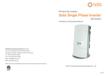
1. Introduction2.Safety Instructions1.2 PackagingImproper use may result in potential electric shock hazards or burns. This manualcontains important instructions that should be followed during installation andWhen you receive the inverter, please check if all the parts listed below are included:maintenance. Please read these instructions carefully before use and keep them forfuture reference.2.1 Safety SymbolsSafety symbols used in this manual, which highlight potential safety risks and importantsafety information, are listed as follows:2WARNING:WARNING symbol indicates important safety instructions, which if notcorrectly followed, could result in serious injury or death.NOTE:431NOTE symbol indicates important safety instructions, which if not correctlyfollowed, could result in some damage or the destruction of the inverter.CAUTION:PV Grid Tie InverterSolis Mini Single Phase InverterInstallation and Operation ManualCAUTION, RISK OF ELECTRIC SHOCK symbol indicates important safetyinstructions, which if not correctly followed, could result in electric shock.CAUTION:CCAUTION, HOT SURFACE symbol indicates safety instructions, which if notcorrectly followed, could result in burns.2014, Ningbo Ginlong Technologies Co., Ltd.Ver 2.25Part NO.16Description2.2 General Safety InstructionsNumberPV grid tie inverter12Wall mounting bracket123Locking screws4AC connector15DC connectors1 pair6Manual1WARNING:Please don’t connect PV array positive( ) or negative(-) to the ground, it couldcause serious damage to the inverter.WARNING:Electrical installations must be done in accordance with the local and nationalelectrical safety standards.Table 1.1 Material list.4.5.
3. Overview2.Safety InstructionsWARNING:3.1 Front Panel DisplayTo reduce the risk of fire, over-current protective devices are required for gridcircuits connected to the inverter.CAUTION:Risk of electric shock. Do not remove cover. There is no user serviceableparts inside. Refer servicing to qualified and accredited service technician.CAUTION:The PV array (Solar panels) supplies a DC voltage when it is exposed to light.CAUTION:Risk of electric shock from energy stored in capacitors of the Inverter. Do notremove cover until 5 minutes after disconnecting all sources of supply. Servicetechnician only. Warranty may be voided if any unauthorized removal of cover.CAUTION:The surface temperature of the inverter can reach up to 75 (167 F).To avoid risk of burns, do not touch the surface when inverter is operating.Inverter must be installed out the reach of children.2.3 Notice For UseThe inverter has been constructed according to the applicable safety and technicalguidelines. Use the inverter in installations that meet the following sepcification ONLY:Figure 3.1 Front Panel Display3.2 LED Status Indicator LightsThere are three LED status indicator lights in the front panel of the inverter. Left LED:POWER LED (red) indicates the power status of the inverter. Middle LED: OPERATIONLED (green) indicates the operation status. Right LED: ALARM LED (yellow) indicatesthe alarm status. Please see Table 3.1 for detailsLightDescriptionStatusONThe inverter can detect DC power2.The electrical installation must meet all the applicable regulations and standards.OFFNo DC power or low DC power3.The inverter must be installed according to the instructions stated in this manual.ONThe inverter is operating properly.OFFThe inverter has stopped to supply power.1.Permanent installation is required.POWER4.The inverter must be installed according to the correct technical specifications.OPERATION5.To startup the inverter, the Grid Supply Main Switch (AC) must be switched on, beforeFLASHINGthe solar panel's DC isolator shall be switched on. To stop the inverter, the Grid SupplyMain Switch (AC) must be switched off before the solar panel's DC isolator shall beswitched off.ALARMThe inverter is initializing.ONAlarm or fault condition is detected.OFFThe inverter is operating properly.Table 3.1 Status Indicator Lights.6.7.
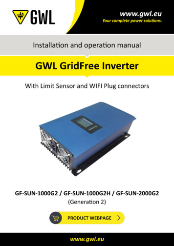
4. Installation3. Overview3.3 Keypad4.1 Select a Location for the InverterThere are four keys in the front panel of the inverter(from left to right):To select a location for the inverter, the following criteria should be considered:ESC, UP, DOWN and ENTER keys. The keypad is used for:The temperature of the inverter heat-sink could up to 75 .Scrolling through the displayed options (the UP and DOWN keys);The inverter is designed to work in extreme temperatures. The ambient operatingAccess to modify the adjustable settings (the ESC and ENTER keys).3.4 LCDtemperature range is from -25 to 60 .If there is more than 1 inverter installed together, A minimum 300mm clearanceshould be kept between each inverter. The bottom of the inverter should be 500mmThe two-line Liquid Crystal Display (LCD) is located at the front panel of the Inverter,clearance to the ground.300mmInverter operation status and data;Service messages for operator;300mmwhich shows the following information:Alarm messages and fault indications.300mm500mm300mm500mm300mmFigure 4.1 Inverter Mounting clearanceVisibility of the LED status indicator lights and the LCD located at the front panel ofthe inverter should be considered.Adequate ventilation must be provided if the inverter is to be installed in a confined space.NOTE:Nothing should be stored on or placed against the inverter.8.9.
4. Installation4. Installation4.2 Mounting the InverterPlease use suitable fixings for wall type (e.g. use dynabolts for brick, masonry, etc).DCEABFigure 4.2 Wall Mount BracketInverter should be mounted in a vertical position as shown in Figure 4.2. The steps toStep1Step2mount the inverter on the wall are given as follows:Step3Figure 4.3 Inverter Mounting1. Locate the wall studs in the desired location and align the wall mount bracket overthe studs. Mark the mounting holes. For masonry walls, the mounting holes should beWARNING:for a suitable dynabolt type mounting system.Inverter must be secure on the bracket by screws (point D and E).Otherwise inverter could fall off the bracket.2. Make sure bracket is horizontal. Ensure that the A, B and C mounting holes (in Figure4.2) are aligned with the wall's most secure points (e.g. wall studs in case of clad4.3 Electrical Connectionsbuilding materials).WARNING:Bracket must be mounted vertically on a vertical wall surface.3. Lean the inverter to the left, then hang on the inverter to the bracket through the leftside slot of the heat-sink (Figure 4.3 step1).4. Push inverter to the right side then turn the inverter to the front, and align the right sideslot of heat-sink to the bracket (Figure 4.3 step2)The inverter is designed for electrical connection without removing the cover. The meaningof the symbols located at the bottom of the inverter are listed in Table 4.1.All electricalinstallations must be in accordance with all local and national electrical codes .DC Positive DC input terminalDC-Negative DC input terminalDC SWITCHSwitch of DC input terminals(optional)COMCommunication connection equipment terminal (Optional)GRIDGrid wires connection equipment terminal5. Push inverter to the left side to make the bracket thought the slot. Use M4 25 stainlesssteel screws and washers at holes D and E to secure the mounting hooks to the rear ofTable 4.1 Terminalsthe inverter (Figure 4.3 step3).10.11.
4. Installation4. InstallationThe electrical connection of the inverter must follow the steps listed below:The steps to assemble the DC connectors are listed as follows:i) Strip off the DC wire for about 7mm, Disassemble the connector cap nut (see Figure 4.6).1. Switch the Grid Supply Main Switch (AC) OFF.2. Switch the DC Isolator OFF.3. Assemble PV input connector to the Inverter.Before connecting inverter, please make sure the PV array open circuit voltage iswithin the limit of the inverter.The Maximum input voltage is 450V for Solis-mini-700 Solis-mini-1000Solis-mini-1500 Solis-mini-700-LV Solis-mini-1000-LVThe Maximum input voltage is 500V for Solis-mini-2000 Solis-mini-2500Please don’t connect PV array positive or negative pole to the ground, it couldFigure 4.6 Disassemble the Connector Cap nutii) Insert the wire into the connector cap nut and contact pin as shown in Figure 4.7.cause serious damages to the inverter.Before connection, please make sure the polarity of the output voltage of PV arraymatches the“DC ”and “DC-”symbols.Figure 4.7 Insert the Wire into the Connector Cap nut and contact piniii) Crimp the contact pin to the wire using a proper wire crimper as shown in Figure 4.8Figure 4.4 DC ConnectorFigure 4.5 DC- ConnectorPlease use qualified DC cable for PV system.Figure 4.8 Crimp the contact pin to the wireiv) Insert the contact pin to the top part of the connector and screw up the cap nut tothe top part of the connector (as shown in Figure 4.8).12.13.
4. Installation4. InstallationFigure 4.9 Connector with Cap nut Screwed onFigure 4.11 AC Grid Terminal Connector Insidev) Then connect the DC connectors to the inverter. Small click will confirm connection(as shown in Figure 4.10).Each Solis mini single Phase Inverter is supplied with an AC grid terminal connector,which is shown in Figure 4.12.Figure 4.10 Connect the DC Connectors to the InverterFigure 4.12 AC Grid Terminal Connector4. Assemble the grid connector of the inverter.2For all AC connections, 2.5- 4mm 105 cable is required to be used. Please make surethe resistance of cable is lower than 1.5 ohm. If the wire is longer than 20m, it'srecommended to use 4mm 2 cable.The steps to assemble the AC grid terminal connectors are listed as follows:a) Disassemble the AC connector. Strip the AC wires about 6mm,Solis-mini-700 Solis-mini-1000 Solis-mini-1500 Solis-mini-2000 Solis-mini-2000are for 208 240V grid.Solis-mini-700-LV Solis-mini-1200-LV are for 100 127V grid.WARNING:There aresymbols marked inside the connector ( see Figure4.11), the Line wire of grid must be connected to“L”terminal; the Neutral wireof grid must be connected to“N”terminal; the Earth of grid must be connectedto“ ”(see Figure 4.11).14.Figure 4.13 Stripped AC Wires.15.
4. Installationb) Fix the green and yellow wire to the ground terminal. Fix the red(or brown) wire to L(line) terminal. Fix the blue wire to N(Neutral). Tight the screws on the connector (asshown in Figure 4.14). Please try to pull out the wire to make sure the it’s wellconnected.4. InstallationMaximum AC side over current protectionTo protect the AC connection line of the inverter, we recommend installinga device for protection against over current and leakage with the followingcharacteristics:RatedvoltageRated outputpowerCurrent 6AInverterSolis-mini-700Figure 4.14 Connect Wires to the LV127V700W10ASolis-mini-1000-LV127V1200W16Ac) Tighten the cap nut to the terminal (as shown in Figure 4.15).5. Inverter monitoring Connection.The inverter can be monitored by Wi-Fi or GPRS functions. All the communicationfunctions are optional (Figure 4.18), please refer to communication connectioninstructions.Smart phone monitoringFigure 4.15 Tight Up the Cap on the TerminalGPRS monitoringd) Connect the AC grid terminal connector to the inverter. Small click will confirmconnection (as shown in Figure 4.16).InternetWi-Fi monitoringRouterWeb serverPC monitoringWi-Fi boxWi-Fi monitoringFigure 4.16 Connect the AC Connector to the InverterFigure4.18 Wi-Fi communication function.16.17.
5. Start & Stop6. OperationDuring normal operation, the display alternately shows the power and the operation5.1 Start the Inverterstatus with each screen lasting for 10 seconds (see Figure 6.1). Screens can also beTo start up the inverter, it is important that the following steps are strictly followed:scrolled manually by pressing the UP and DOWN keys. Press the ENTER key to access to1. Switch the Solar Supply Main Switch (AC) ON first.the Main Menu.Pressing theESC keycalls back theprevious menu.2. Switch the DC Isolator ON. If the voltage of PV arrays are higher than start up voltage,the inverter will turn on. The red LED power will light, and the LCD shows the company'sname and the inverter model.Power3424W01-01-2014 12:04GinlongSolis-mini-1000ManufacturerModel nameInformationUP/DOWNSettings5 secStartMain MenuUP/DOWN orauto-scroll(10 sec)Figure 5.1 Company Name and Inverter Model on LCDUP/DOWNAdvanced Info.Status: Generating01-01-2014 12:043. When both the DC and the AC grid sides supply to the inverter, it will be ready toPressing theENTER keygives access tothe main menu.generate power. Initially, the inverter will check both its internal parameters and theparameters of the AC grid, to ensure that they are within the acceptable limits. At theUP/DOWNAdvanced settingssame time, the green LED will flash and the LCD displays the information ofFigure 6.1 Operation OverviewINITIALIZING.4. After 30-180 seconds (depending on local requirement), the inverter will start to6.1 Main Menugenerate power. The green LED will be on continually and the LCD displaysGENERATING.There are four submenus in the Main Menu (see Figure 6.1):1. InformationWARNING:Do not touch the surface when the inverter is operating. It may behot and cause burns.2. Settings3. Advanced Info.4. Advanced Settings5.2 Stop the Inverter6.2 InformationTo stop the inverter, the following steps must be strictly followed:1. Switch the Grid Supply Main Switch (AC) OFF.The Solis mini single Phase Inverter main menu provides access to operational data and2. Wait 30 seconds. Switch the DC Isolator OFF. All the LEDs of the inverter will be offinformation. The information is displayed by selecting "Information" from the menu andin a minute.then by scrolling up or down.18.19.
6. OperationDisplayDurationV DC 350.8VI DC5.1A10 secV Grid 230.4VI Grid8.1AStatus: GeneratingPower: 988W10 sec10 sec6. OperationDescription6.3 SettingsV DC: Shows input voltage value.The following submenus are displayed when the Settings menu is selected:I DC: Shows input current value.1.Set TimeV Grid: Shows the grid's voltage value.I Grid: Shows the grid's current value.2.Set Address6.3.1 Set TimeStatus: Shows instant status of the Inverter.This function allows time and date setting. When this function is selected, the LCD willPower: Shows instant output power value.display a screen as shown in Figure 6.3.Grid FrequencyF Grid 50.06Hz10 secF Grid: Shows the grid's frequency value.Total Energy0258458 kwh10 secTotal generated energy value.This Month: 0123kwhLast Month: 0123kwh10 secNEXT ENT OK ESC 01-01-2010 16:37Figure 6.3 Set TimeThis Month: Total energy generated this month.Press the UP/DOWN keys to set time and data. Press the ENTER key to move from oneLast Month: Total energy generated last month.digit to the next (from left to right). Press the ESC key to save the settings and return tothe previous menu.Today:15.1kwhYesterday: 13.5kwh10 secToday: Total energy generated today.Yesterday: Total energy generated yesterday.6.3.2 Set AddressThis function is used to set the address when the inverter is connected to the PC. TheTable 6.1 Information listaddress number can be assigned from “01”to “99”(see Figure 6.4). The default addressPressing the ESC key returns to the Main Menu. Pressing the ENTER key locksnumber of Solis mini single Phase Inverter is “01”.(Figure 6.2(a)) or unlocks (Figure 6.2 (b)) the screen.YES ENT NO ESC Set Address: 02Figure 6.4 Set Address5.2 Stop the Inverter(a)(b)Press the UP/DOWN keys to set the address. Press the ENTER key to save the settings.Press the ESC key to cancel the change and return to the previous menu.Figure 6.2 Locks and Unlocks the Screen of LCD.20.21.
6. Operation6. Operation6.4 Advanced Info - Technicians Only6.4.3 Standard No.The screen shows the reference standard of the inverter (see Figure 6.11).NOTE:To access to this area is for fully qualified and accredited technicians only.Standard: G83/2Select “Advanced Info.” from the Main Menu to display a screen and be able to access tothe following information.Figure 6.11 Example of Standard of the Inverter1.Alarm Message6.4.4 Version2.Temperature3.Standard No.The screen shows the model version and the software version of the inverter4.Version(see Figure 6.12).5.Communication DataModel: 08Software Version: D20001The screen can be scrolled manually by pressing the UP/DOWN keys. Pressing the ENTERkey gives access to a submenu. Press the ESC key to return to the Main Menu.Figure 6.12 Model Version and Software Version6.4.1 Alarm Message6.4.5 Communication DataThe display shows the 10 latest alarm messages (see Figure 6.9). Screens can be scrolledThe screen shows the internal data of the inverter (see Figure 6.13), which is for servicemanually by pressing the UP/ DOWN keys. Press the ESC key to return to the previoustechnicians only.menu.01-05: 01 25 E4 9D AA06-10: C2 B5 E4 9D 55Alarm0: OV-G-VTime: 27-11 Data: 7171Figure 6.13 Communication DataFigure 6.9 Alarm Message6.5 Advanced Settings - Technicians Only6.4.2 TemperatureThe screen shows the temperature inside the inverter (see Figure 6.10).NOTE:To access to this area is for fully qualified and accredited technicians only.For Technicians only.Temperature046.6 Select Advanced Settings from the Main Menu to access the following options:1.Select Standard2.Grid ON/OFFFigure 6.10 Temperature inside the inverter.22.23.
6. Operation6. OperationFor Model Model Solis-mini-700-LV Solis-mini-1000-LV6.5.1 Selecting StandardOV-V: 120---150VNOTE:The inverter is customized according to the local standard before shippingto the customer. The " User-Def" function can be only used by the serviceengineer and must to be allowed by the local energy supplier.NOTE:Before to using this function, please set "GRID OFF" to stop inverter (referto Section 6.5.2).NOTE:This function is for technicians use only.UN-V: 80---110VOV-G-F: 50.3---52.0Hz(60.3—62.0Hz)UN-G-F: 47.0---49.5Hz(57.0—59.5Hz)Press the UP/DOWN keys to scroll through items. Press the ENTER key to edit the highlighteditem. Press the UP/DOWN keys again to change the setting. Press the ENTER key to save thesetting. Press the ESC key to cancel changes and returns to the previous menu.NOTE:Please, set "Grid ON" to start up the inverter after the settings (refer toSection 6.5.2). Otherwise the inverter won't start up.This function is used to select the grid's reference standard (see Figure 6.14).YES ENT NO ESC Standard: G83/2Figure 6.146.5.2 Grid ON/OFFThis function is used to start up or stop the power generation of Solis mini single PhaseInverter (see Figure 6.16).6.5.3 Clearing EnergyPress the UP/DOWN keys to select the standard (AS4777, VDE4105, VDE0126, UL-240V,UL-208V, MEX-CFE, G83/2, EN50438 DK, EN50438 IE, EN50438 NL and “User-Def”function). Press the ENTER key to confirm the setting. Press the ESC key to cancelchanges and returns to previous menu.Grid ONGrid OFFFigure 6.16 Set Grid ON/OFFScreens can be scrolled manually by pressing the UP/DOWN keys. Press the ENTER keySelecting the “User-Def” menu will access to the following submenu (see Figure 6.15),to save the setting. Press the ESC key to return to the previous menu.OV-V: 262VUN-V: 210VFigure 6.15Below is the setting range for “User-Def”. Using this function, the limits can be changedmanually.For Model Model Solis-mini-700 Solis-mini-1000 Solis-mini-1500 Solis-mini-2000OV-V: 240---270VUN-V: 180---210VOV-G-F: 50.3---52.0Hz(60.3—62.0Hz)UN-G-F: 47.0---49.5Hz(57.0—59.5Hz).24.25.
7. Maintenance8. Trouble ShootingSolis mini single phase inverter does not require any regular maintenance. However,Alarm MessageFailure descriptioncleaning the dust on heat-sink will help the inverter to dissipate the heat and increaseOV-G-VOver grid voltageits life time. The dust can be removed with a soft brush.UN-G-VUnder grid voltageOV-G-FOver grid frequencyUN-G-FUnder grid frequencyG-IMPHigh grid impedanceCAUTION:Do not touch the inverter's surface when it is operating. Some parts of the invertermay be hot and cause burns. Turn off the inverter (refer to Section 5.2) and wait fora cool-down period before before any maintenance or cleaning operation.The LCD and the LED status indicator lights can be cleaned with a damp cloth if they are toodirty to be read.NO-GRIDNo grid voltageOV-DCOver DC voltageOV-BUSOver DC bus voltageUN-BUSUnder DC bus voltageGrid interferenceGRID-INTF.NOTE:Never use any solvents, abrasives or corrosive materials to clean the inverter.INI-FAULTInitialization system faultOV-TEMOver TemperatureGround faultGROUND-FAULTILeak-FAULTHigh Grid leakage currentRelay-FAULTRelay check faultDCinj-FAULTHigh DC injection current8. Trouble ShootingTable 8.1 Fault message and descriptionThe inverter is designed in accordance with the most important international grid-tiedstandards and safety and electromagnetic compatibility requirements. Before delivering tothe customer, the inverter has been subjected to several tests to ensure its optimal operationand reliability.NOTE:If the inverter displays any alarm message as listed in Table 8.1; pleaseturn off the inverter (refer to Section 5.2 to stop your inverter) and wait for 5minutes before restarting it (refer to Section 5.1 to start your inverter). If thefailure persists, please contact your local distributor or the service center.Please keep ready with you the following information before contacting us.In case of failure, the LCD screen will display an alarm message. In this case, the invertermay stop feeding into the grid. The failure descriptions and their corresponding alarmmessages are listed in Table 8.1:1. Serial number of the Inverter;2. The distributor/dealer of the Inverter (if available);3. Installation date;4. The description of problem (i.e. the alarm message displayed on the LCD and the statusof the LED status indicator lights. Other readings obtained from the Information submenu(refer to Section 6.2) will also be helpful.);5. System design for the PV array configuration (e.g. number of panels, capacity of panels,number of strings, etc.);6. Your contact details.26.
mini-2000Solis-mini-2500450Vdc450Vdc50 400Vdc50 gDC SwitchOptionalG83/2DC SwitchOptionalG83/2
Solis-mini-1000-LVSolis-mini-700LV450Vdc50 400Vdc0.7kW1kW0.8kW1.1kW120/127V96 150V9.4A5.5A270W*417H*124D(mm)5.6kgDC SwitchOptionalG83/2.30.
2. The electrical installation must meet all the applicable regulations and standards. 3. The inverter must be installed according to the instructions stated in this manual. 4. The inverter must be installed according to the correct technical specifications. 5. To startup the inverter, the Grid Supply Main Switch (AC) must be switched on, before