Transcription
Brushless DC motors
2
3
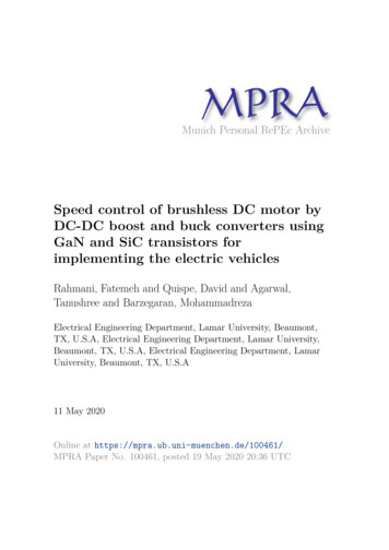
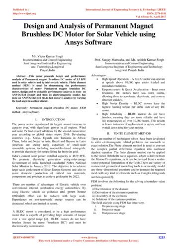
VFD VS ECM(PM Motors) Both take AC and convert to DCVFD is generally 3ØECM 1Ø in 3Ø outVFD & ECM Both have RectifiersVFD & ECM both have transistor outputsVFD Out put is to AC motorECM Out put is to DC motorVFD motor is induction motorECM motor is a synchronousECM can spin a motor at much higher speedsECM rotor has permanent magnetsVFD’s induce Lots of noiseAC motors not as efficient as DC motors
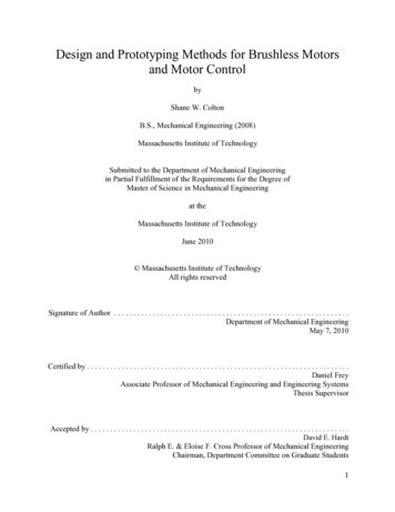
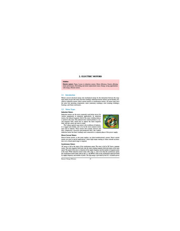
VFD Introduction VFDs convert AC to DC then DCto AC(at varying frequency andACDCACvoltage)Rectifier460 V, 60 HzInverter640 V, DC307 V, 40 HzVFDs allow the motor to operate and consume electricity as if it werethe right sized horsepower for the job.10
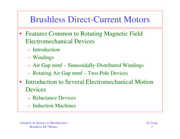
VFD Layout11
ECM Controller12
ECM wiring13
What is ECM An Electronically commutated MotorThree phase wound statorPermanent Magnet RotorDC brushless motorSynchronous motorIncorporated inverter14
ECM motor Parts15
Motor SpeedSynchronous Motor R.P.M. AC Frequency in Hertz X 120Number of Poles in Motor16
Types of ECM Permanent magnet synchronous Switching Reluctance Induction (asynchronous) Stepper17
Variable Speed Ties it all Together Fully Modulated ECMprovides indoor air with:– Quiet Operation– Dehumidification– Steady Temperatures - Nomore Hot Flashes18
Types of ECM motors1. On OFF2. Multiple speed1. High2. Medium3. Low3. Variable speed1. 0-100%19
ECM motor characteristics Torque linear with speedMaximum torque when stationaryHigh efficiencyPermanent magnets on rotorFixed armature20
ECM rotor position detection Hall effect sensorsA transducer that varies its output voltage in response to a magnetic field Rotary encoderAn electro-mechanical device that converts the angular position or motion of a shaft or axle to an analog or digital codeCan be based on BACK-EMF 21
ECM construction Conventional or Inrunner– Permanent magnets are part of the rotor.– Three stator windings surround the rotor Outrunner or external-rotor– Radial relationship between the coils andmagnets is reversed– The stator coils form the center or core of themotor, the permanent magnets spin within anoverhanging rotor which surrounds the core.22
ECM Benefits Lower Annual operating costs (25%-75%)– PSC motors 12-45% Efficiency– ECM motors 65-75% Efficiency Small as 80 watts Reduced Temperature (around ambient)– PCM motors 90-150 F. Quieter running Lower drying effect during heating season Reduced motor stress– Reduced starts & slewed speed ramps More Precise Unlimited air flow selection23
ECM versions24
ECM Module Replacement25
ECM Module Replacement Tools Required:– 5/16” nut driver– ¼” wrench Time: approx 20 minutes Techs Needed: 1Instructions: Remove filter access and blower access panels (indoorside)– Furthest left panel is removed first– Top does not need to be taken off of unit Unplug (2) molex connectors from the ECM module Remove (2) ¼” bolts from the top of the ECM module Replace26
ECM Module Replacement27
ECM Module ReplacementRemove (2) ¼” bolts from top of ECM module28
ECM Module ReplacementDisconnect molex plug from Module.29
ECM Troubleshooting30
Power connectionsModels 2.0/ 2.3 / 2.5Jumper 1 and 2 for 120 VACno jumper for 240 VAC31
32
33
Model X13 Connections34
Modle X13 Speed inputs 1-535
ECM motor3 PH DC MotorAprx. 12 Ω Winding to Winding36
One way to test motor & driveSome Furnaces Units Req. Jumper24 VACHot24 VACCommonPower (4 &5) & ground (3)37
One more way to test motor & driveRuns to 50%Some Furnaces Units Req. Jumper9 VDC9 VDCCommonPower (4 &5) & ground (3)38
Motor Running with system faults Test controllerCheck WiringCheck inputsCheck powerCheck airflow settingsCheck air distribution system for dirt,closed dampers, registers and grills. Measure external static pressure (across fanor system) if above design fix system39problem.
Motor not running Check high voltage inputs– Voltage within 15% of ratings Check speed reference inputsCheck motor windingsCheck controllerRun function tests.40
Symptom analysis Motor rocks on starting (Normal) Motor won’t start ( check pwr, connectins,check motor shaft movement, test motor) Motor rocks but won’t start (checkconnections, check wheel tightness, checkcontroller) Motor oscillates up and down ( Normal withno load apply load and retest)41
Symptom analysis Motor starts however, runs erratically. (Check power sag, check connections, checkcontrol output, check system static, checkrestrictions) Keep static pressure to aminimum Evidence of moisture ( Fix source ofmoisture)42
Motor test Motor windings R 20 Ώ Each winding within 10% of each other R 100KΏ to ground43
ECM OperationECM Electrically Commutated Motor44
ECM- Sequence of Operation 1st stage Cooling call– Ramps to 25% CFM for 1 minute.– Ramps up to 40% CFM for 7.5 minutes.– Ramps to 50-65% CFM for remainder of 1st stagecooling call. 2nd stage call during 1st stage operation– Ramps to 80% CFM for 7.5 minutes.– Ramps to 100% for remainder of 2nd stage cooling call.45
ECM- Sequence of Operation 2nd stage Cooling call (from “off” position)– Ramps to 50% CFM for 1 minute.– Ramps up to 80% CFM for 7.5 minutes.– Ramps to 100% CFM for remainder of 2nd stagecooling call.46
EBM47
EBM plenum FanTake top of to get tomotor48
49
Fan Speed Control50
Speed Setup51
ECM Engine Controller52
Adapter Board53
Customer Supplied TerminalInterface54
Options Module55
EBM plenum Motor Wiring56
EBM plenum Motor WiringWith PWRto motorplace 10volts to 8and 7 andfan will 57run
EBM Plenum Motor58
EBM motor59
Connections60
Tabular Performance Data61
Airflow form DP62
HP VS BHP1. HP is the output horsepower rating of an engine, while BHP is the input brakehorsepower of an engine.2. B HP is the measurement of an engine’s power without any power losses, whileHP is BHP less the power losses.3. HP is measured by hooking up the engine to a dynamometer, while BHP ismeasured in a controlled environment without anything attached to the engine.1 bhp equals to: 745.5 watts1.01389 ps33,000 ft lbf/min42.2 BTU/min63
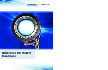
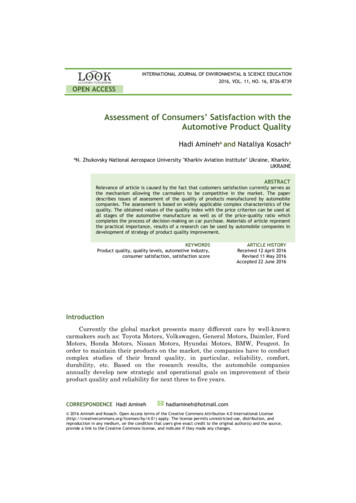
Supply Duct Static Pressure1000 rpm,IGV 100%OpenSystemResistanceAt DesignSystemResistanceAt Part LoadA1000 rpm,IGV PartiallyOpenD12 bhpFan ModulationCurveAirflow (1000 cfm)64 American Standard Inc. 1996
VFD Out put is to AC motor ECM Out put is to DC motor VFD motor is induction motor ECM motor is a synchronous . ECM Troubleshooting . 30. Power connections Models 2.0/ 2.3 / 2.5. Jumper 1 and 2 for 120 VAC no jumper for 240 VAC. 31. 32. 33. Model X13 Connections. 34. Modle X13 Speed inputs 1-5. 35.