Transcription
Brushless DC MotorsHandbook
General Dynamics Mission Systems (GDMS)Precision Pointing and Motion Systems isexperienced and ready to build a high-qualitysystem solution for your specific application. Copyright 2005 Axsys Corporation Rev. 07/2005Axsys believes the information in this publication isaccurate as of its publication date. Such information issubject to change without notice. Axsys is not responsiblefor inadvertent errors. All brands and product names aretrademarks of their respective owners.
Brushless DC MotorsTable of ContentsAlpha-Numeric Index. . 2Mechanisms . 71User’s Guide. . 3Direct Drive Motor Assemblies . 72GDMS Introduction . 4Scanners . 73Brushless DC Motors . 5Actuators . 74Commutating BrushlessFeedback Packages. . 75DC Motors . 9Capabilities . 76Glossary . 23Overview . 77Conversion Table . 26DC Motors . 782 Phase Brushless MotorsSelection GuideAC and Stepper Motors . 79DC and AC Tachometers . 80by Peak Torque. 28Resolvers/Synchros . 813 Phase Brushless MotorsSelection GuideScanners. . 82Actuators. . 83by Peak Torque. 31Packages, Assembliesand Servosystems . 84Limited Angle Slotless Motors(Toroidally Wound) Selection GuideDC Motor Design Guide. 85by Peak Torque. . 47Typical Performance Curves ExcursionTables . 48Limited Angle Moving Coil MotorsSelection Guide . 62Dual Winding MotorsSelection Guide . 671
Brushless DC MotorsAlpha-Numeric IndexSelection Guide Tables1600C-059. 291600C-059J . 321600M-060.332375H-050 . 342376-057 . 352376-064 . 363730H-071 . 374125-120 . 684500C-080. 384500C-080C . 304750J-110 . . .396000S-146. .406000S-210. .416000S-360. .426000S-400. .436700-154 . 698338-157 . 448700-100 . 708860B-330 . 458860B-475 .46BTM10-S . 49BTM10-AD. . 50BTM10-N-2 . 51BTM14-E . 52BTM15-C. 53BTM16-B . 54BTM18-G . 55BTM18-L . 56BTM30-E . 57BTM34-Q1 . 58BTM34-S . 59BTM35-B . 60BTM48-B . 61RA2500A-077 . 63RA2500B-078 . 64RA6240B-119 . 65RA6800-119 . 662 Phase Motors . 283 Phase Motors . 31Limited Angle (Toroidal) . 47Moving Coil Motors . 62Dual Winding Motors . 672
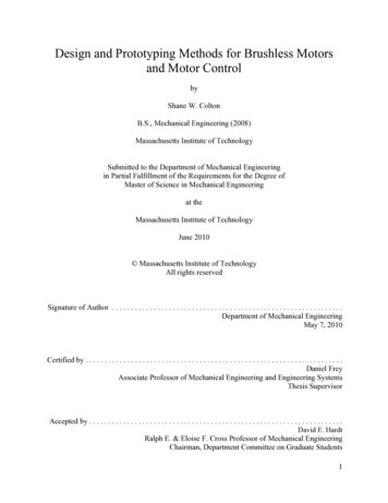
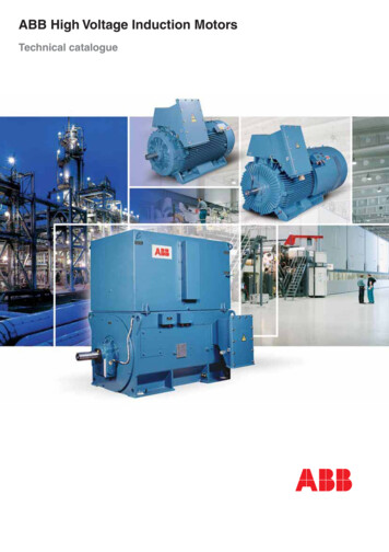
Brushless DC MotorsThe Selection Guide is the first pagein each brushless motor section.TheSelection Guide lists the products featured,basic parameters, and the page where thedatapage can be found. Immediately following the Selection Guide are the individual datapages. On each datapage are endand cutaway views of the product, as well aswinding and performance data.User’s GuideThe GDMS Brushless DC Motor Manual isorganized in a manner which makes it easyto access the product performanceinformation. Starting with the DesignGuides, you should be able to locate thespecific brushless motor which best suitsyour needs.Sample DatapageModelNumber6980G-180Brushless DC Motors2375H-050(800) 777-3393Brushless DC Motors .006Ø.146 -.000 THRUC'BORE Ø.236 X .156 .010 DP7 EQ. PLCS ONØ6.650 BSCBLULEADWIRES ARE #22 AWG TYPE "E",PER MIL-W-16878/4, 12" MIN. LG.RED.231.800 MAX.500 MAX.1.59# 10-32 UNF-2BX .50 DP MIN.7 EQ PLCS ON Ø6.650 BSCGRNProductsMotorDrawingØ4.650 MIN.2 PLCS .000Ø6.980 -.002Ø2.32 MAX. TYP. .001Ø4.499 -.000 .001Ø.940 -.000Ø6.330 MAX.Ø1.52 MIN. TYP.REDBLKWHT/REDØ2.375LEADWIRES ARE #22 AWG TYPE "E",PER MIL-W-16878, 36" MIN. LG.WHT/BLK .000-.001.015 .010MTG. anceDataParameterParameterPeak PeakTorque(Tp) (Tp)TorquePowerat Tpat(PTpp) calTimeTimeConstant(e) (te)ElectricalConstantMechanicalTimeTimeConstant( (Fo) .160391Momentof InertiaMomentof orque(Tf) mp.Max.Max.AllowableWdg.Wdg.Temp. C/watt C/watt C C14155155oz oz5.513482832WeightWeightNumber of PolesNumber of PolesNumber of PhasesNumber of PhasesWindingConstants34160Winding ConstantsWinding ConstantsParameterUNITSParameterUNITSResistance (R)ohmsResistance (R)ohmsVoltage at Tp (Vp)voltsVoltage at Tp (Vp)voltsCurrent at Tp (Ip)ampsCurrent at Tp (Ip)ampsTorque Sensitivity (Kt)oz-in/ampTorque Sensitivity (Kt)oz-in/ampBack E.M.F. (Kb)volts/rad/secBack E.M.F. (Kb)volts/rad/secInductance (L)millihenriesInductance (L)millihenriesTOL.TOL. 12.5% 12.5%NominalNominalNominalNominal 10% 10% 10% 10% 30% 6.350.7143.048 .010MTG. DIM.ROTATION: FIELD ROTATES CW.325WHEN VIEWEDFROM LEAD SIDEWITH THE FOLLOWING SEQUENCE:WHITE/RED& WHITE/BLACKROTATION: FIELD ROTATES CWCOMMON AND POSITIVE VOLTAGEWHEN TOVIEWEDFROMBLACK.LEAD SIDEAPPLIEDRED THENWITH THE FOLLOWING SEQUENCE:RED , GREEN-; BLUE , GREEN-;BLUE , RED-.REDREDWHITE/REDWHITE/BLACKBLACKGREEN .73.450.85217.415250.12012.67.1
Brushless DC Motorsaerospace, and medical industries. Equippedfor innovation, with a world-class team ofengineers and a global support network,GDMS is uniquely able to apply this highperformance technology to your systemneeds, at a competitive cost.Motion Control PackagesFor decades, GDMS has provided solutionsfor complex applications such as ultrasonicimaging systems, semiconductor process,mechanisms, aircraft actuation and missileguidance systems.The mechanismsection of the GDMS Brushless DC MotorManual gives a brief overview.Design and ManufacturingYour GDMS design begins with adetailed review of your specifications by ourengineers. If you have not established formalspecifications, our engineers will help develop them with you.We use computer aideddesign programs, design, and process controlspecifications to assure the product will meetyour specifications.Design GuidesAt the end of this catalog, you will find aDC Motor Design Guide, which promptsyou to answer the necessary questions aboutyour current motor requirements. TheDesign Guide is especially useful when yourproject calls for a custom solution.Werecommend you make copies of it to use asworksheets when deciding on your brushless motor requirements.GDMS Motion ControlProducts IntroductionGDMS manufacturing cycle brings with theestablishment of a Materials RequirementsPlan (MRP).With the aid of an integratedcomputer planning/scheduling system,detailed production schedules are generatedto ensure on-time material delivery, optimaloutput, and inventory levels.HeritageGDMS has been serving thecommercial,industrial and defense motioncontrol industries for 40 years, supplyinghigh performance components and systemsthat stand up to the most rigorous environments.We supply high performance products that withstand 700 g’s of shock, 15,000lbs of pressure, and temperature ranges from-55ºC to 200ºC, for applications fromaerospace to medical, textile to robotics.Customer ServiceAt GDMS, service does not endwith the delivery of your products. Serviceand support are our most important responsibilities, and we meet them with our network of technical support staff that stretchesaround the world. Our engineering, manufacturing and quality experts - in fact, allemployees in our entire organization - areready to serve you from concept, throughdevelopment, to order delivery, and beyond.From our inception, GDMS hascontinuously challenged technologicallimitations, developing state-of-the-artmotors, position feedback devices, andelectromechanical assemblies for the rapidlyevolving commercial, industrial, defense,Quality AssuranceWe have established the internal qualitysystems required for high-reliability commercial and defense programs. GDMSQuality System is certified to AS9100.4
Brushless DC MotorsManufacturing OperationGDMS has a modern 60,000square foot facility in San Diego, staffed bydedicated employees.We can easily accommodate contracts from the developmentphase through full-scale production.motors this energy can be handled bythe drive circuits.2. The stator, which is wound member,may be mounted in a substantial heatsink to minimize temperature rise andprolong bearing life.We encourage factory tours. Our operationsinclude an extensive CNC machine shop,automated armature winding station,organized work centers, and environmentaland performance testing equipment.3. Where long life is a requirement, theabsence of brushes normally increasesthe motor’s life expectancy to that ofthe bearings.4. In high-cleanliness applications,unacceptable brush wear particles areeliminated.Brushless DC Motors5. The EMI (ElectromagneticInterference)normally associated with thearcing of the brush commutator interfaceis eliminated in the brushless motor.Brushless DC controllers are generallyfree of major EMI contributors.The mechanical switching of currentassociated with brush motors is replacedwith electronic switching in brushlessmotors. Brushless DC motors are not simplyAC motors powered by an inverter, insteadthese devices use rotor feedback devices sothat the input wave forms are kept in propertiming with the rotor position. Some formof electronic commutation switching is necessary for all motors, except in the limitedangle devices.6. For explosive environments, a brushlessmotor can be used without specialhousing elements necessary toexplosion-proof a conventional DCmotor.Brushless DC motors with suitable controlelectronics can be directly substituted forsimilarly-sized brush DC motors. BrushlessDC motors provide several advantages:7. Although brushes have been usedextensively in space environments,their preparation is expensive and timeconsuming.The brushless motorrequires much less preparation.1. Brushless units may be operated atmuch higher speeds and at full torqueat these speeds, resulting in a motorwith considerable power output for itssize. High speed operation is especiallydifficult for conventional DC motorsbecause the high energy that must beswitched by the brushes is destructiveand shortens motor life. In brushlessTypical ApplicationsBrushless DC motors have the sameelectrical performance operating (transferfunction) characteristics as brush-commutated DC motors, and can be used in thesame applications.They provide high starting torque, variable bi-directional speed5
Brushless DC Motorsoperation, and precision position and velocity servo loop capabilities.They can alsoreplace AC motors in spindle and rotarytable drives where the higher torque DCmotor can drive the spindle directly, eliminating the need for a belt and pulley.Basic ComponentsA brushless motor system consists of fourbasic subassemblies:1. A stator wound with electromagneticcoils which are connected in single andpoly-phase configurations.2. A rotor consisting of a soft iron coreand permanent magnet poles.3. A rotor position sensor providing rotorThe gearless DC motor drive is ideally suited tohigh acceleration applications requiring improvedresponse for rapid start/stop actions.ApplicationsEquipmentVelocity ServosDisk Memory Spindle DriveVideo Tape RecorderSilicon Water SpinnerCAT ScannerInfrared ImagerArtificial HeartsCryogenic CompressorFuel PumpAir Bearing SpindlePosition ServosSpace VehicleHigh Power Density6Brushless DC AdvantageLong Life,Low-EMIHigh Speed,No Brush DebrisHigh Speed,Long LifeLow-EMI,Low Audible NoiseHigh Speed,Low-EMILong Life,No Brush DebrisNo Brush DebrisNo ArchingNo Brush DebrisNo Brush DebrisHigh SpeedVacuum OperationLow-EMIOptical SystemNo Brush DebrisStable PlatformLow-EMIRobotLow Thermal ResistanceAirborne ActuatorLow Thermal ResistanceVacuum Operation
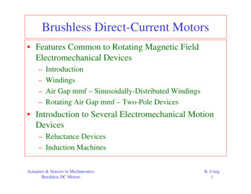
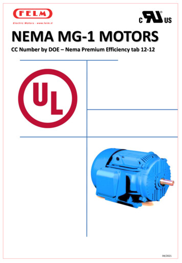
Brushless DC MotorsStator Leadwiresposition to the required resolution.4. Commutation logic and switching electronics to covert rotor position information to the proper stator phase excitation.PermanentMagnetsRotor CoreWindingsStatorThe stator for a brushless DC motor is alaminated steel core with coils of magnetwire embedded and connected in two ormore phases so that by sequentially excitingthese phase winding, a rotating electromagnetic field can be generated.StatorA) Inner Rotor Brushless DC MotorStator LeadwiresSince both iron and copper losses in thebrushless DC motor take place in the stator,generated heat is easily transferred to thesurroundings. A motor with an inner rotor isbetter in this regard due to the larger statorarea in contact with the mounting surfaces.Rotor CoreStator WindingsPermanentMagnetsB) Outer Rotor Brushless DC MotorFig. 1 Brushless Motor ConfigurationsRotorsIn all continuous rotation brushless DCmotors, the permanent magnetic field is onthe rotor.The winding supplying the rotating electromagnetic field are in the stator.The rotor can be designed inside of the stator, as in a conventional motor, or outside ofthe stator. See Figure 1A and 1B.The innerrotor design is generally used in incrementalmotion application where low inertia andfast response are required.The outer rotorconfiguration provides a more rigid structure for the permanent magnets and hashigher inertia. It is used in high speed applications where a stiff structure is required tocounter the centrifugal forces acting on thepermanent magnets, in velocity loop applications where the additional rotor inertia isdesired for velocity stabilization, or whenthe additional inertia is insignificant relativeto the total inertia as in a memory diskdrive.Position SensorsThere are several ways to sense brushlessrotor position. Rotor position sensing isnecessary so the stator winding excitationcan be controlled to keep the electromagnetic field in leading quadrature withrespect to the rotor field.These methods fallinto three categories: photo-electronic,electromagnetic, and magnetic.PhotoElectronicA set of photo-transistors and LEDs arecoupled across a shutter which is keyed tothe rotor and has windows in the properpattern to control the phase excitation. If ashaft angle encoder is required in the system for normal shaft position sensing, aseparate pattern track can be included onthe disk for motor commutation.The output of an absolute encoder can also be usedin a sine cosine ROM or as input to a digi-7
Brushless DC Motorstal comparator to develop the commutationwaveform.choice while IGBT’S are most common inhigh voltage brushless motors driver wherethe motor voltages are on the order of several hundred volts.ElectromagneticElectromagnetic sensors use a soft iron target and a set of wound coils. Changes inthe coil inductance are sensed and decodedto verify rotor position. Eddy currentdevices using metallic targets can also beused in the same manner. Brushless resolverare commonly used in sine cosine systemsas the source of the phase quadrature waveform.Also, for high power applications, mostmodern three phase brushless drivers aredesigned to operate directly off of the 230VAC or 440 VAC power line, eliminatingthe need for separate power supply lines, andthe need for a separate power supply to generate the switch bus voltages.These drivesystems almost always use IGBT powerdevices because of the high voltagesencountered and the high efficiencyachieved with direct line powered operation.MagneticHall effect sensors, magneto-resistors, ormagneto-diodes are used in magnetic sensors.These devices work directly off of therotor poles so that the alignment of thesensors can be accomplished during themanufacture of the stator.They become apart of the stator assembly so that the userneed only install the rotor to have analigned system.In a sine-cosine system, the electronics module is a two phase bipolar amplifier.The sensor output are first decoded or demodulate(if required), and then amplified by a fourquadrant power amplifier.To reduce powerdissipation in the amplifier, pulsewidth modulation is often used.This type of system ismore costly than the digitally switched system. For this reason, is used only when theapplications needs the smooth, low rippletorque of a sinusoidally-commutated brushless motor.ElectronicsThe electronics module, which can beinternal to the motor housing or placed onan external printed circuit board, receivesthe signals form the position sensors anduses digital logic to develop the wave-formsthat are used to control the switches.Theseswitches are usually power MOSFET,IGBT, or bipolar transistor devices.Theselection of the type of power switchdepends largely on the application andincludes factors such as the motor voltage,peak motor current, PWM frequency, andthe operating characteristics of the motor.Brushless DC motor controllers offer manypower levels and commutation options.Standard controller products are availableproviding closed loop control of speed ortorque, accepting Hall sensor, opticalencoder or resolver position sensor signals.Often in low power applications, the controlelectronic are an integral part of the motorand range from single commutation andswitching circuits to complete speed controlsystems. Many IC’s combining commutation, current sensing, fault detection, andIn general, power MOSFET’S, because ofthe very low “on” resistance exhibited bythis type of device, are the switches of8
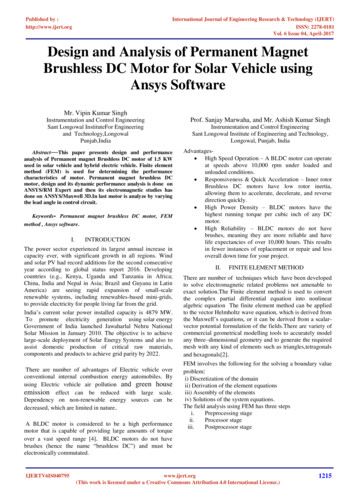
Brushless DC MotorsRotor PositionElectrical Degreespower switch drive functions provide costeffective Brushless DC motor control.Torque0ACommutating Brushless DCMotors90180270360Torque0BTorque and Winding CharacteristicsThe basic torque waveform of a brushlessDC motor has a sinusoidal or trapezoidalshape. It is the result of the interactionbetween the rotor and stator magnetic fields,and is defined as the output torque generated relative to rotor position when a constantDC current is applied between two motorleads.This torque waveform is qualitativelyequivalent to the voltage generated waveform at the two motor leads when themotor is driven at a constant speed byanother motor.The frequency is equal to thenumber of pole pairs in the motor times thespeed in revolutions per second.Commutated Excitation134121143112Torque with iKtCommutatedExcitation0Figure-2. Switch mode commutation of a twophase brushless DC motor.The brushless DC motor will exhibit torquespeed characteristics similar to a conventional DC motor when the stator excitation is inproper alignment with the rotor’s magneticfield.The stator excitation may be squarewave or sinusoidal. Ideally, the stator excitation may be square wave or sinusoidal.Ideally, the stator excitation should beapplied in a sequence to provide a constantoutput torque due to the finite commutation angle.The commutation angle is theangle the rotor rotates through before thewinding are switched. Ripple torque is typically expressed as a percentage of average topeak torque ratio. It is present whenever thewinding are switched by a step functioneither electrically via solid state switches ormechanically via brushes.Figure-3. Switch mode commutation of a threephase delta wound brushless DC motor.9
Brushless DC MotorsIn brushless DC motors designed for squarewave excitation, the ripple torque can bereduced by reducing the commutationangle by using a higher number of phases,which also improves motor efficiency.Figure 2 shows the commutation pointsand output torque for a two phase brushlessmotor.The commutation angle is 90 electrical degrees which yields the largest rippletorque of about 17% average to peak.Athree phase delta system is shown in Figure3.The commutation angle is 60 degrees andthe ripple toque is approximately 7% average to peak. Since two-thirds of the available winding are used at any one time,compared to one-half for the two phasesystem is more efficient.Figure-4. BEMF Trapezoidal waveform.03020405060107012The torque waveform indicated in Figure 2and 3 have a sinusoidal shape.A trapezoidaltorque waveform can be obtained by usinga salient pole structure in conjunction withthe necessary lamination/ winding configuration. In practice, the trapezoidal torquewaveform does not have a perfectly flat top.Manufacturing and other cost considerations result in an imperfect trapezoidalwaveform. An example is Figure 4 wherethe generated voltage waveform across twoterminals of a brushless motor designed fortrapezoidal torque generation is Shown.Figure 5 is an example of a 12 phase brushless motor with a trapezoidal torque waveform.With the center terminal of the phases connected to the supply voltage, thephases are switched to ground during theindicated commutation angle of 30 electrical degrees. Only three phases are “on” atany one time.This motor was designed tosatisfy the requirements of high efficiencyand minimum ripple torque for a precisionpointing and tracking space gimbal application. In applications requiring smooth01020110100908Rotor Position-Electrical -5.Torque waveform for 12 phase brushlessDC motor.10
Brushless DC Motors0AIA0BIf the motor currents are supplied in thefollowing relationships:IBIA I CosuIB I SinuRotor Position Electrical DegreesThe torque output of the motor is:0A Torque withIA Const.90180270360T TA TBT I KT(Sin2u Cos2u )T I KT0B Torque withIB Const.This analysis indicates that the sinusoidallydriven brushless motor has linear characteristics similar to a conventional DC motorand has minimum ripple torque.Threephrase winding can be connected in eitherwye or delta configuration. Excitation canbe switch mode or sinusoidal drive.Theswitch mode drive is the most commonlyused system because it results in the mostefficient use of the electronics.Two switchesper phase terminal are required for theswitch mode drive system.Therefore, onlysix switches are required for either the wyeor delta configuration.IA I COSuIB I SINuNormalized 1.0Torque0.5901802703602T IK SIN uB T2T IK COS uA TFigure-6.Two phase sinusoidal excitation.The delta winding form a continuous loop,so current flows through all three windingregardless of which pair of terminals isswitched to the power supply. Since theinternal resistance of each phase is equal,the current divides unequally, with twothird of the total current from one windingto another as the winding are commutated.operation at low speed, or where the motoris operated in a position loop, a sinusoidaldrive system should be considered. Figure 6is an example of a two phase motordesigned for sine wave drive.The torque output of each phase is:TA IA KT Cos uTB IB KT Cos uWhereFor the wye connection, current flowsthrough the two winding between theswitched terminals.The third winding isisolated and carries no current. As thewinding are commutated, the full load current must be switched from terminal to terminal. Due to the electrical time constantof the winding, it takes a finite amount ofIA current in phase AIB current in phase BKT torque sensitivity of motoru rotor position in electrical degrees11
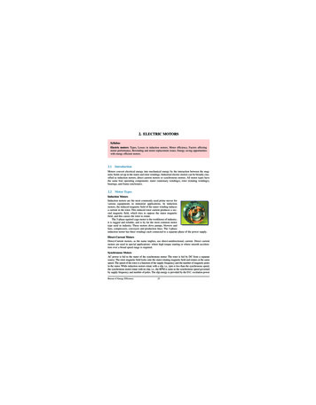
Brushless DC MotorsThe commutation points and output torquefor a two phase brushless motor were shownin Figure 2.The commutation angle is 90electrical degrees, and the winding areswitched “on: 45 electrical degrees beforethe peak torque position.The current polarity must be reversed for negative torquepeaks.The commutation waveform for thismotor are shown in Figure 7. Sensor outputand alignment is shown in figure 7A. TheS1 output leads the phase B torque positionby 45 electrical degrees.time for the current to reach full value. Athigh motor speeds, the electrical time constant may limit the switched current fromreaching full load value during the commutation interval, and thus limits the generatedtorque.This is one of the reasons the deltaconfiguration is preferred for applicationsrequiring high operating speed. Other considerations are manufacturing factors whichpermits the delta configuration to be fabricated with lower BEMF constant, resistance, and inductance. A lower BEMF constant allows the use of more common lowvoltage power supplies, and the solid stateswitches will not be required to switchhigh voltage. For other than high speedapplications, the wye connection is preferred because it provides grater motorefficiency when used in conjunction withbrushless motors designed to generate atrapezoidal torque waveform.There are several methods for aligning theS1,2 sensors with respect to the stator winding. As shown in Figure 2, the peak torqueposition of phase B coincides with the zerotorque position of phase A and vice versa.Sensor S1 can be aligned to the phase Bwinding by applying a constant current tophase A.The rotor will rotate to phase A’szero torque position. S1 should be positioned so that its output just switches from alow to high logic state at 45 electricaldegrees counter-clockwise from phase A’szero torque position.Sensor Timing and AlignmentA brushless DC motor duplicates the performance characteristics of a DC motoronly when its winding are properly commutated. Proper commutation involves thetiming and sequence of stator windingexcitation.Winding excitation must betimed to coincide with the rotor positionthat will produce optimum torque.Theexcitation sequence controls the polarity ofgenerated torque, and therefore the direction of rotation.Another method is to align the position sensors to the BEMF waveform. Since theBEMF waveform is qualitatively equivalentto the torque waveform, the motor can bedriven at a constant speed by another motor,and the position sensors aligned to the generated BEMF waveform.The sensor transition points relative to the BEMF waveformshould be as indicated in Figures 2 and 7.For critical applications which require thecommutation points to be optimized, themotor should be operated at its rated loadpoint, and then the position sensors shouldbe adjusted until the average winding current is at its minimum value.To facilitatesensor alignment, GDMS can supply statorsRotor position sensors provide the information necessary for proper commutation.Sensor output is decoded by the commutation logic electronics.The logic signals arefed to the power drive circuit which activates the solid state switches to commutatethe winding.12
Brushless DC Motors01S1 0CW Rotor Position - Electrical Degrees601201802403003601S2 0(A)onQ1 offonQ2 offonQ3 off(S1 l S2)(S1 l S2)(B)(S1 S2)onQ4 offl(S1 l S2) 0B 3-4 0 0A 1-2 0 VS-VS(C)Q4Q20A12Q130BQ34(D) VS -VSFigure-7. Sensor output, commutation logic, andand winding excitation waveform for atwo phase brushless DC motor.with reference marks to which the positionsensors can be aligned.The commutation points and output torquefor a three phase brushless motor was shownin Figure 3.The commutation angle is 60electrical degrees, and the winding areswitched “on” at 30 electrical degrees beforethe peak torque position, and switched “off” at 30 electrical degrees after the peaktorque position.The current polarity forFigure-8. Sensor output, commutation logic andwinding excitation waveform for a three phasebrushless DC motor.each phase during each commutation segment is shown in Figure 3B.The commutated output torque versus motorposition(in electrical degrees) is shown inFigure 3C.13
Brushless DC MotorsTo identify each of the 6 commutation terminals, a minimum of three l
The GDMS Brushless DC Motor Manual is organized in a mannerwhich makes it easy to access the productperformance information. Starting with theDesign Guides,you should be able to locatethe specific brushless motor which best suits your needs. Sample Datapage. The Selection Guide is the first