Transcription
Energy Research Lab (ERL) – Institute of Energy in Building,FHNWInstitutionUniversity of Applied Sciences and ArtsNorthwestern Switzerland (FHNW)School of Architecture, Civil Engineeringand GeomaticsInstitute of Energy in BuildingLocationGründenstrasse 404132 MuttenzSwitzerlandContact personsProf. Dr. Jürg Bichseljuerg.bichsel@fhnw.ch 41 61 228 55 49Prof. Dr. Ralph Eismannralph.eismann@fhnw.ch 41 61 228 53 61AuthorsManuel Koch, Christof Ackermann, Christoph Messmer, Ralf Dott, Monika Hall29.11.20171
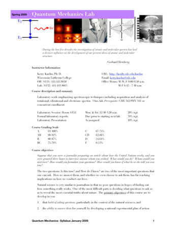
1.1 General PresentationThe Energy Research Lab (ERL) was built in 2013 to test and optimize components for heatand power supply systems in buildings. Testing may focus on the individual performance of acomponent or its role within an entire system. While heat pumps are most often the centralpoint of interest, evaluation has also included phase-change storage, solar-thermal collectors,complex valves and control systems. Recently, photovoltaics and batteries have been of increasing importance in the ongoing research. In addition to the strictly physical experiments,components are regularly operated in interaction with numerical models, extending the scientific range to systems beyond the confines of the laboratory.1.2 Description of the Test Facility1.2.1 The Thermodynamic CoreThe functional core of the laboratory is a 2-stage system, capable ofdynamically supplying multipletest components with temperaturecontrolled water. The first stageconsists of two 1600 L tanks (6)with hot and cold water, which areconnected by one heat pump, simultaneously heating and coolingthe corresponding sides. An energy dissipater on the hot side provides a second degree of freedomto regulate the temperatures in thetanks.Supplied by the first stage, thesecond stage consists of three pairs Figure 1. (1) Photovoltaics (2) Thermodynamic core stage 2 (3)Heat pump (4) Domestic hot water storage (5) Phase-changeof smaller hot- and cold-side tanks storage (6) Thermodynamic core stage 1 (7) Climate chamber(2). Two of these pairs containwater. The third pair contains a water-glycol mixture. The purpose of these smaller tanks is toprovide quick buffer capacity for generating the desired input profiles for test components.Furthermore, the temperature difference between these pairs is smaller than the temperaturedifference between the big tanks, allowing for easier and more accurate power control.Figure 2. Second stage of the thermodynamic core (left). Heat pump and domestic hot water storage (right).2
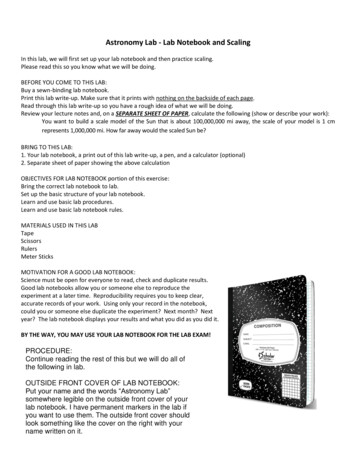
In application, this system is used to emulateThermodynamic Core: Specificationssources and sinks, such as geothermal heat exL/h6000changers, solar-thermal collectors or room heating. Max. mass flowThe output values for the emulated componentsMax. powerkW16are generated through numerical simulation. TheTemperature range C-10 90physical outputs are then fed to real test components, such as heat pumps (3) or domestic hotwater storage (4), shown in Fig. 3.Figure 3. Second stage of the thermodynamic core with emulation models and real test components1.2.2 Climate ChamberA climate chamber (7) has been added to the laboratory in2015 and is used to condition air for testing air-fed heatpumps. Thus, it can be thought of as an extension of the thermodynamic core. Additionally, the climate chamber can beused to study frosting and defrosting on the external heat exchanger and their effect on the performance of the heat pump.Climate Chamber: Specificationsm3/h3500Temperature range C-20 40Humidity range%15 98Max. air volumeFigure 4. Climate chamber andexternal unit of split heat pump.1.2.3 Phase-Change StorageThe laboratory is equipped with a 10 m3 water-based phasechange storage (5) from Viessmann/Isocal. The state of thestorage can be measured with a total of 41 temperature sensors. Of those, 21 are located inside the storage, 18 in the earthon its sides and two in the earth below. If needed, the storagecould be filled with an alternative fluid, such as paraffin oil ora glycol solution. This would change the melting/freezingpoint (i.e. operating point) of the storage as well as its capacity.Figure 5. Phase-change storage3
1.2.4 Electric InstallationsIn order to extend the research capabilities for householdPV Emulator: Specificationselectric systems, a highly instrumented electric distributorkW10with connections for a photovoltaic system, heat pump, bat- Max. powertery and household appliances has been installed. While aMax. voltageV600real photovoltaic system is available in the laboratory, itsMax. currentA20dependence on the weather makes it unsuitable for reproducible, standardized testing. Therefore, a photovoltaicemulator (Regatron “TopCon Quadro”) has been added to the electric setup. On the demandside, an electric load emulator with up to 8 kW and thermal energy recovery has been installed in the laboratory. Unlike real household appliances, this allows the execution of defined load profiles. It also requires significantly less space. With this setup, control strategiesfor electric power management can be investigated.1.2.5 Sensors and Data AcquisitionThe laboratory features a range of sensors for solar radiation, wind speed and ambient temperature. Additionally, the various technical installations and test components contain a largenumber of sensors, mostly measuring temperatures, flows and electric powers. These sensorsfeed into event-driven database logging through a self-developed SCADA (Supervisory Control and Data Acquisition) system, which supports all common industrial bus systems. Thehardware components were mostly supplied by National Instruments.1.2.6 SimulationThe primary software used for simulationsis Matlab/Simulink in combination with theCARNOT Blockset Toolbox, which offers awide array of standard components, rangingfrom controllers and valves to entire buildings. CARNOT’s open source nature isfrequently used to modify existing components to fit individual requirements and toadd additional component models to thetoolbox.CARNOT Blockset Features (selection) Hydraulics Pneumatics Heat pumps Control systems Thermal storage Photovoltaics Solar-thermal collectors Geothermal systems Combustion heaters Thermal house models Water tapping cycles External weather dataFigure 6. Example of a simple CARNOT model with parameter mask for the heat pump4
1.2.7 Roof InstallationsOn the roof of the laboratory, six mounting points for photovoltaic or solar-thermal modulesare installed. These can be manually tilted and rotated.1.2.8 Test ComponentsListed below are the components currently installed in the laboratory for performance evaluation. They were selected to be representative of components installed in typical single-familyhouses and work together as a well-balanced water heat pumpViessmannVitocal 300-GPowerkW8.4Air/water heat pumpViessmannVitocal 200-SPowerkW4.75DHW storageViessmannVitocell V100 CVWVolumeL390DHW storageViessmannVitocell 100-B CVBVolumeL500Solar-thermal collector(3x)Energie Solaire AbsorberAS/TS 1/TSSSurfacem21.78Photovoltaic panel (4x) Panasonic12 HIT-N240PowerkWp2.9InverterSMASTP 5000TL-20PowerkW3BatteryLGResu 6.5CapacitykWh5.91.3 Examples of Previous Studies1.3.1 Study 1: SOFOWAThe SOFOWA study has explored the potential of combining solar-thermal collectors (ST),water-based phase-change storage (PCS), photovoltaics (PV), combined photovoltaic-thermalpanels (PVT) and heat pumps (HP) for space and domestic hot water heating in single-familyhouses. The phase-change storage in the laboratory was experimentally characterized in orderto build a numerical model in CARNOT. The annual performance evaluations were conducted as pure simulations.The study consists of two parts. In the first part, five systems for heat generation and storage(#1-5) were tested on the standard house model SFH45. This model has a defined space heating load (SHL) and was taken from IEA SHC Task 44 HPT Annex 38. Three systems (#1-3)included an air/water heat pump (A/W-HP) while dividing the roof area between solarthermal collectors and photovoltaics. The system with only solar-thermal collectors on theroof (#1) had a much larger space heating storage (SHS), which also included domestic hotwater (DHW). In system #4 (shown in Fig. 7), the air/water heat pump was “replaced” withphase-change storage and a brine/water heat pump (B/W-HP), while the solar-thermal part ofthe roof area was changed from glazed to unglazed, which is advantageous for convectiveheat gains at low ambient temperatures. System #5 is similar to system #4, except the roofarea is no longer divided, but fully covered with combined photovoltaic-thermal panels.5
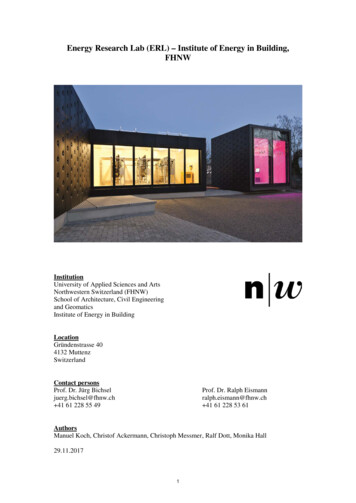
Power and heat systems: Part 1A/W-HPSHSSHLSPF7.5 kW10 m34.0 kW13.242 m27.5 kW900 L4.0 kW4.0350 m27.5 kW900 L4.0 kW3.0410 m2 unglazed 40 m26.0 kW10 m34.0 kW4.2550 m2 PVT6.0 kW10 m34.0 kW4.2SHLSPF7.5 kW4.47SystemST150 m228 m2PVB/W-HPPCSPower and heat systems: Part 2SystemST613 m2 unglazedPVB/W-HPPCS8.0 kW10 m3A/W-HPSHSSPF: Seasonal Performance Factor before StorageFigure 7. System #4In Fig. 8, the annual consumption of grid electricity for systems #1, #2, #3 and #5 as well as areference with no solar technology for SFH45 are shown. During summer, none of the testedsystems had significant grid power consumption, since the photovoltaic panels in systems #25 supplied enough power to cover the domestic hot water production and the solar-thermalcollector in system #1 has a very high SPF. During the colder part of the year, grid powerconsumption of systems #2 and #3 is almost identical, although the mixed system #2 has ahigher SPF than the purely photovoltaic system #3. This can be attributed to the superior SPFof solar-thermal collectors compared to air-water heat pumps (compare system #1). System#1 has similar grid power consumption as systems #2 and #3 during winter, but stretches thephase of almost no grid power consumption much further into the seasonal transition. This isowed to the large collector area in spring and to the large space heating storage in autumn.The grid power consumption of system #5 is similar to systems #2-3 in shape, but lower sinceunder cold conditions, the combination of phase-change storage and a brine/water heat pumphas a higher SPF than an ambient air/water heat pump. The performance of the combinedphotovoltaic-thermal panels in system #5 is comparable to that of the split configuration insystem #4. However, system #5 feeds more electric power into the grid.6
Figure 8. Annual grid electricity consumption of the systems for SFH45In the second part, system #6 was tested on the modified house model SFH45*, which has abigger space heating load than SFH45. Fig. 9 shows the monthly energy balance of the phasechange storage. This includes freezing and melting of the storage fluid, gains from the solarthermal collectors, gains and losses from the ground surrounding the storage and the energydelivered to the brine/water heat pump. Two points may be highlighted here: First, the solargains are almost completely out of sync with the heating demand and much of the gains insummer appear to be lost to the ground. Second, the thermal gains from the ground are themost significant energy source during winter.Figure 9. Monthly energy balance of the PCS for SFH45*In conclusion, it has been shown that the systems proposed in this project can reach an annualSPF of 4.0 and higher. In comparison, this is almost as good as a ground source heat pumpwith conventional drilling (SPF -4.5) and much better than an air source heat pump (SPF 3).A particular finding of this study was the dominance of convective heat gains as opposed tosolar radiation gains in unglazed solar-thermal collectors, when operated below ambient temperatures with a heat pump. The energy sources in descending order of importance are convective gains on the collector, ground gains, phase change gains and radiation gains on thecollector.7
1.3.2 Study 2: LEWASEF (in prog.)A subtask of LEWASEF (successor study ofSOFOWA) is the evaluation of the performance of air/water heat pumps in combination with photovoltaics and a battery. Compared to phase-change storage, a battery iscommonly much more restricted in capacity.Therefore, a particular focus of this study ison a learning controller, which shifts the loadcycles of the heat pump to time slots withphotovoltaic overproduction.A CARNOT model of the system has beenbuilt for preliminary testing and to ensure theselected components are well balanced andappropriately scaled for a single-familyhouse. In the next stage, this model will beintegrated into the laboratory setup for valiFigure 10. LEWASEF system with PV and batterydation. While the actual heat pump, domestichot water storage, battery and photovoltaic inverter will be used, the thermodynamics of thehouse, the weather and the domestic electric power consumption will be provided by the simulation and implemented using the thermodynamic core and the electric emulators. The desired result of the study is a validated system for affordable and effective power and heat generation in single-family houses.1.4 Maintenance and CollaborationsThe laboratory was designed in cooperation with the university’s school of architecture and isoperated by the Institute for Energy in Building FHNW. The main collaborators are the SwissFederal Office of Energy as well as various industrial partners. It is also used in the practicaleducation of students from various majors, such as architecture, engineering and life sciences.1.5 Additional InformationAdditional information about the laboratory and the institute can be found architektur-bau-geomatik/institute/iebau(currently only available in German)Located next to the ERL is the Lighting and Façade Lab. Placed on a rotating platform, thisinstallation is used to test daylight, glare, artificial lighting, façade constructions and blinds.1.6 Relevant PublicationsDott, R.; Afjei, T.; Genkinger, A.; Dailbard, A. et al. “Heat Pump Models: A Technical Report of Subtask C, Report C2, Part C” Models of Sub-Components and Validation forthe IEA SHC Task 44 / HPT Annex 38 (2013)Haller, M.Y.; Dott, R.; Ruschenburg, J.; Ochs, F. and Bony, J. “Part A: General SimulationBoundary Conditions: A Technical Report of Subtask C, Report C1, Part A” Modelsof Sub-Components and Validation for the IEA SHC Task 44 / HPT Annex 38 (2013)Haller, M.Y.; Bertram, E.; Dott, R.; Afjei, T. et al. “Part A: Summary: A Technical Report ofSubtask C, Report C2, Part A” Models of Sub-Components and Validation for theIEA SHC Task 44 / HPT Annex 38 (2013)8
Hadorn, J.-C. “Solar and Heat Pump Systems for Residential Buildings” ISBN: 978-3-43303040-0 (2015)Dott, R.; Winteler, C.; Afjei, T.; Genkinger, A. “SOFOWA Final Report” Institute for Energyin Building, FHNW Muttenz (2016)Dott R.; Haller M.Y.; Ruschenburg J.; Ochs F. and Bony J. “The Reference Framework forSystem Simulations of the IEA SHC Task 44 / HPT Annex 38 Part B: Buildings andSpace Heat Load A technical report of subtask C Report C1 Part B”, available onhttp://task44.iea-shc.org, 20139
The Energy Research Lab (ERL) was built in 2013 to test and optimize components for heat and power supply systems in buildings. Testing may focus on the individual performance of a