Transcription
Brushless Direct-Current Motors Features Common to Rotating Magnetic FieldElectromechanical Devices––––IntroductionWindingsAir Gap mmf – Sinusoidally-Distributed WindingsRotating Air Gap mmf – Two-Pole Devices Introduction to Several Electromechanical MotionDevices– Reluctance Devices– Induction MachinesActuators & Sensors in Mechatronics:Brushless DC MotorsK. Craig1
– Synchronous Machines– Permanent-Magnet Devices Brushless DC Motors––––––IntroductionTwo-Phase Permanent-Magnet Synchronous MachineVoltage Equations and Winding InductancesTorqueMachine Equations in the Rotor Reference FrameTime-Domain Block Diagrams and State EquationsActuators & Sensors in Mechatronics:Brushless DC MotorsK. Craig2
Features Common to Rotating Magnetic FieldElectromechanical Devices Introduction– A dc machine has windings on both the stationary androtating members, and these circuits are in relative motionwhenever the armature (rotor) rotates. However, due to theaction of the commutator, the resultant mmf produced bycurrents flowing in the rotor windings is stationary.– The rotor windings appear to be stationary, magnetically.– With constant current in the field (stator) winding, torque isproduced and rotation results owing to the force establishedto align two stationary, orthogonal magnetic fields.Actuators & Sensors in Mechatronics:Brushless DC MotorsK. Craig3
– In rotational electromechanical devices other than dcmachines, torque is produced as a result of one or moremagnetic fields which rotate about the air gap of the device.– Reluctance machines, induction machines, synchronousmachines, stepper motors, and brushless dc motors(permanent-magnet synchronous machines), all developtorque in this manner.– There are features of these devices which are common toall, in particular: Winding arrangement of the stator Method of producing a rotating magnetic field due tostator currents– Hence, we cover these common features now.Actuators & Sensors in Mechatronics:Brushless DC MotorsK. Craig4
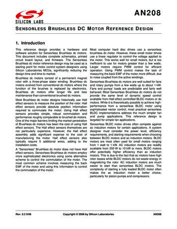
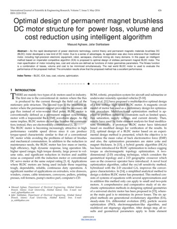
Windings– Consider the diagram of the elementary two-pole, singlephase stator winding.– Winding as is assumed distributed in slots over the innercircumference of the stator, which is more characteristic ofthe stator winding than is a concentrated winding.– The winding is depicted as a series of individual coils. Eachcoil is placed in a slot in the stator steel.– Follow the path of positive current ias flowing in the aswinding.– Note that as1 and as1 are placed in stator slots which span πradians; this is characteristic of a two-pole machine.– as1 around to as1 is referred to as a coil; as1 or as1 is a coilside. In practice a coil will contain more than one conductor.Actuators & Sensors in Mechatronics:Brushless DC MotorsK. Craig5
– The number of conductors in a coil side tells us the numberof turns in this coil. This number is denoted as ncs.– Repeat this winding process to form the as2 – as2 coil andthe as3 – as3 coil, assuming that the same number of turns,ncs, make up each coil.– With the same number of turns in each of these coils, thewinding is said to be distributed over a span from as1 to as3or 60 .– The right-hand rule is used to give meaning to the as axis;it is the principal direction of magnetic flux established bypositive current flowing in the as winding. It is said todenote the positive direction of the magnetic axis of the aswinding.Actuators & Sensors in Mechatronics:Brushless DC MotorsK. Craig6
Elementary Two-Pole, Single-Phase Stator WindingActuators & Sensors in Mechatronics:Brushless DC MotorsK. Craig7
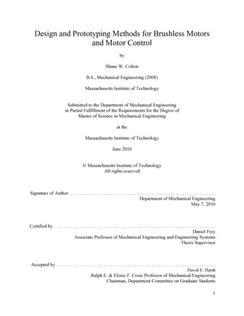
– Now, consider the diagram of the elementary two-pole,two-phase stator windings. Here we have added a secondwinding – the bs winding.– The magnetic axis of the bs winding is displaced ½ π fromthat of the as winding.– Assume that the positive direction of ibs is such that thepositive magnetic axis of the bs winding is at φs ½ πwhere φs is the angular displacement about the statorreferenced to the as axis.– This is the stator configuration for a two-pole, two-phaseelectromechanical device.– The stator windings are said to be symmetrical (as it is usedin electromechanical devices) if the number of turns percoil and resistance of the as and bs windings are identical.Actuators & Sensors in Mechatronics:Brushless DC MotorsK. Craig8
– For a two-pole, three-phase, symmetrical electromechanicaldevice, there are three identical stator windings displaced120 from each other. Essentially all multiphaseelectromechanical devices are equipped with symmetricalstators.Actuators & Sensors in Mechatronics:Brushless DC MotorsK. Craig9
Elementary Two-Pole, Two-Phase Stator WindingsActuators & Sensors in Mechatronics:Brushless DC MotorsK. Craig10
Air Gap mmf – Sinusoidally-Distributed Windings– It is generally assumed that the stator windings (and inmany cases the rotor windings) may be approximated assinusoidally-distributed windings.– The distribution of a stator phase winding may beapproximated as a sinusoidal function of φs, and thewaveform of the resulting mmf dropped across the air gap(air gap mmf) of the device may also be approximated as asinusoidal function of φs.– To establish a truly sinusoidal air gap mmf, the windingmust also be distributed sinusoidally, and it is typicallyassumed that all windings may be approximated assinusoidally-distributed windings.Actuators & Sensors in Mechatronics:Brushless DC MotorsK. Craig11
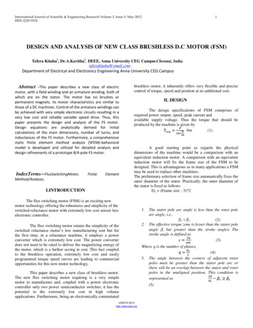
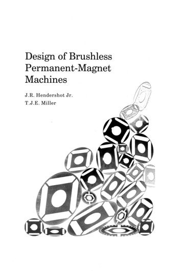
– In the figure, we have added a few coils to the as winding,which now span 120 .– For the purpose of establishing an expression for the airgap mmf, we employ the developed diagram of the crosssectional view obtained by “flattening out” the rotor andstator.– Note that displacement φs is defined to the left of the asaxis since this allows us to position the stator above therotor.– The winding distributions may be approximated as:N as N p sin φsfor 0 φs πN as N p sin φsfor π φs 2 π– Np is the peak turns density in turns/radian.Actuators & Sensors in Mechatronics:Brushless DC MotorsK. Craig12
– If Ns represents the number of turns of the equivalentsinusoidally distributed winding (not the total turns of thewinding) that corresponds to the fundamental componentof the actual winding distribution, then:Ns π 0 N p sin ( φ s ) dφ s 2Np– The sinusoidally-distributed winding will produce a mmfthat is positive in the direction of the as axis (to the right inthe figure for positive ias).– We assume that all of the mmf is dropped across the airgap, as the reluctance of the steel is much smaller(neglecting saturation) than the reluctance of the air gap.– So if the windings are sinusoidally-distributed in space,then the mmf dropped across the air gap will also besinusoidal in space.Actuators & Sensors in Mechatronics:Brushless DC MotorsK. Craig13
Approximate Sinusoidal Distribution of the as WindingActuators & Sensors in Mechatronics:Brushless DC MotorsK. Craig14
Developed Diagram withSinusoidally-Distributed Stator WindingStatorRotorActuators & Sensors in Mechatronics:Brushless DC MotorsK. Craig15
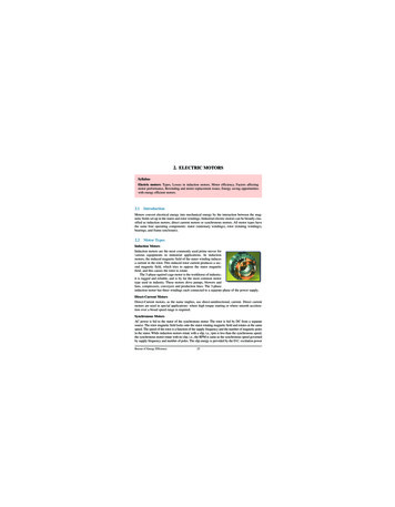
– We need to develop an expression for the air gap mmf,mmfas, associated with the as winding. We will applyAmpere’s Law to two closed paths, shown in the diagram.– For closed path (a), the total current enclosed is Nsias and,by Ampere’s Law,ur u u r this is equal to the mmf drop around thegiven path ( Ñ Hg dL ).– If the reluctance of the rotor and stator steel is smallcompared with the air-gap reluctance, we can assume that½ of the mmf is dropped across the air gap at φ s 0 and ½at φ s π.– By definition mmfas is positive for a mmf drop across theair gap from the rotor to the stator. Thus mmfas is positiveat φ s 0 and negative at φ s π, assuming positive ias.Actuators & Sensors in Mechatronics:Brushless DC MotorsK. Craig16
– This suggests that for arbitrary φs, mmfas might beexpressed as:Nsmmf as ( 0 ) i as2Nsmmf as i as cos φ sNs2mmf as ( π ) i as2– This tells that the air gap mmf is zero at φs ½ π. Checkthis by applying Ampere’s Law to the second closed pathin the figure, path (b). The net current enclosed is zero,and so the mmf drop is zero along the given path, implyingthat mmfas 0 at φ s ½ π.Actuators & Sensors in Mechatronics:Brushless DC MotorsK. Craig17
– Let’s consider the bs winding of a two-phase device. Theair gap mmf due to a sinusoidally-distributed bs windingmay be expressed as:Nsmmf bs i bs sin φ s2Actuators & Sensors in Mechatronics:Brushless DC MotorsK. Craig18
Closed Paths used to Establish mmfasActuators & Sensors in Mechatronics:Brushless DC MotorsK. Craig19
A mmfas Due to Sinusoidally Distributed as WindingActuators & Sensors in Mechatronics:Brushless DC MotorsK. Craig20
Rotating Air Gap mmf – Two-Pole Devices– Considerable insight into the operation ofelectromechanical motion devices can be gained from ananalysis of the air gap mmf produced by current flowing inthe stator winding(s).– Let’s consider the rotating air gap mmf’s produced bycurrents flowing in the stator windings of single-, two-, andthree-phase devices.Actuators & Sensors in Mechatronics:Brushless DC MotorsK. Craig21
Single-Phase Devices– Consider the device shown which illustrates a single-phasestator winding. Assume the as winding is sinusoidallydistributed, with as and as placed at the point of maximumturns density.– Assume that the current flowing in the as winding is aconstant. Then the as winding would establish a stationarymagnetic system with a N pole from 0.5 π φ s 1.5 π and aS pole from -0.5 π φ s 0.5 π.– The air gap mmf is directly related to these poles; indeed,the flux flowing from the N pole and into the S pole iscaused by the air gap mmf.Actuators & Sensors in Mechatronics:Brushless DC MotorsK. Craig22
Elementary Two-Pole, Single-PhaseSinusoidally-Distributed Stator WindingActuators & Sensors in Mechatronics:Brushless DC MotorsK. Craig23
– What happens when the current flowing in the as windingis a sinusoidal function of time? Let’s assume steady-stateoperation:I as 2I s cos ω e t θ esi ( 0 ) – Capital letters denote steady-state instantaneous variables;Is is the rms value of the current; ω e is the electrical angularvelocity; θ esi(0) is the angular position corresponding to thetime zero value of the instantaneous current.– The air gap mmf expressed for the as winding is:NsNsmmf as i as cos φ s 2Is cos ω e t θ esi ( 0 ) cos φ s22Actuators & Sensors in Mechatronics:Brushless DC MotorsK. Craig24
– Consider this expression for a moment. It appears that allwe have here is a stationary, pulsating magnetic field. Letus rewrite this expression using a trig identity:mmf as Ns2 12Is cos ω e t 2θ esi( 0 ) φ s 1 cos ω e t θ esi ( 0 ) φ s 2 – The arguments of the cosine terms are functions of timeand displacement φ s. If we can make an argument constant,then the cosine of this argument would be constant.ω e t θ esi ( 0 ) φ s C1ω e t θ esi ( 0 ) φ s C2dφ s ωedtdφ s ωedt– What does this mean?Actuators & Sensors in Mechatronics:Brushless DC MotorsK. Craig25
– If you run around the air gap in CCW direction at an angularvelocity ω e, the first term in the expression for mmfas willappear as a constant mmf and hence a constant set of N andS poles. On the other hand, if we run CW at ω e, the secondterm in the expression for mmfas will appear as a constantmmf.– In other words, the pulsating air gap mmf we noted standingat φ s 0 (or any fixed value of φ s) can be thought of as two,one-half amplitude, oppositely-rotating air gap mmf’s(magnetic fields), each rotating at the angular speed of ω e,which is the electrical angular velocity of the current.– Since we have two oppositely rotating sets of N and S poles(magnetic fields), it would seem that the single-phasemachine could develop an average torque as a result ofinteracting with either.Actuators & Sensors in Mechatronics:Brushless DC MotorsK. Craig26
– A single-phase electromechanical device with the statorwinding as shown can develop an average torque in eitherdirection of rotation.– Note that this device is a two-pole device, even thoughthere are two two-pole sets, as only one set interacts withthe rotor to produce a torque with a nonzero average.Actuators & Sensors in Mechatronics:Brushless DC MotorsK. Craig27
Two-Phase Devices– Consider the two-pole, two-phase sinusoidally distributedstator windings shown.– For balanced (i.e., variables are equal-amplitude sinusoidalquantities and 90 out of phase) steady-state conditions, thestator currents may be expressed as:I as 2I s cos ω e t θ esi ( 0 ) I bs 2Is sin ω e t θ esi ( 0 ) – The reason for selecting this set of stator currents willbecome apparent.– The total air gap mmf due to both stator windings (assumedto be sinusoidally distributed) may be expressed by addingmmfas and mmfbs to give mmfs.Actuators & Sensors in Mechatronics:Brushless DC MotorsK. Craig28
– The total air gap mmf due to the stator windings is:Nsmmf as i as cos φ s2Nsmmf bs i bs sin φ s2Nsmmf s ( i as cos φ s i bs sin φ s )2– Substitution:I as 2I s cos ω e t θ esi ( 0 ) I bs 2Is sin ω e t θ esi ( 0 ) – Result:Nsmmf s ( i as cos φ s i bs sin φ s )2Nsmmf s 2Is cos ω e t θ esi ( 0 ) φ s 2Actuators & Sensors in Mechatronics:Brushless DC MotorsK. Craig29
Elementary Two-Pole, Two-PhaseSinusoidally-Distributed Stator WindingActuators & Sensors in Mechatronics:Brushless DC MotorsK. Craig30
– It is interesting to note that we have only one rotating airgap mmf or rotating magnetic field.– Set the argument equal to a constant, take the derivativewith respect to time, and we find that the argument isconstant ifdφ s ωedt– If we travel around the air gap in the CCW direction at ω e,we will always see a constant mmfs for the balanced set ofcurrentsI 2I cos ω t θ ( 0 ) asI bs s eesi 2Is sin ω e t θ esi ( 0 ) – Hence a single rotating air gap mmf is produced. Theactual value that we would see as we travel around the airgap at ω e would depend upon the selection of time zero andour position on the stator at time zero.Actuators & Sensors in Mechatronics:Brushless DC MotorsK. Craig31
– With the assigned positive direction of current in the givenarrangement of the as and bs windings shown, the balancedset of stator currents produces a mmfs that rotates CCW,which is desired for conventional purposes.– In the case of the single-phase stator winding with asinusoidal current, the air gap mmf can be thought of astwo oppositely-rotating, constant-amplitude mmf’s.However, the instantaneous air gap mmf is pulsating evenwhen we are traveling with one of the rotating air gapmmf’s. Unfortunately, this pulsating air gap mmf or set ofpoles gives rise to steady-state pulsating components ofelectromagnetic torque.Actuators & Sensors in Mechatronics:Brushless DC MotorsK. Craig32
– In the case of the two-phase stator with balanced currents,only one rotating air gap mmf exists. Hence, the steadystate electromagnetic torque will not contain a pulsating ortime-varying component; it will be a constant with thevalue determined by the operating conditions.Actuators & Sensors in Mechatronics:Brushless DC MotorsK. Craig33
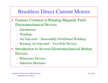
Three-Phase Devices– The stator windings of a two-pole, three-phase device areshown in the figure.– The windings are identical, sinusoidally distributed with Nsequivalent turns and with their magnetic axes displaced120 ; the stator is symmetrical.– The positive direction of the magnetic axes is selected so asto achieve counterclockwise (CCW) rotation of the rotatingair gap mmf with balanced stator currents of the abcsequence.Actuators & Sensors in Mechatronics:Brushless DC MotorsK. Craig34
– The air gap mmf’s established by the stator windings maybe expressed by inspection as:Nsmmf as i as cos φ s2Ns2 mmf bs i bs cos φ s π 23 Ns2 mmf cs i cs cos φ s π 23 – As before, Ns is the number of turns of the equivalentsinusoidally distributed stator windings and φ s is theangular displacement about the stator.Actuators & Sensors in Mechatronics:Brushless DC MotorsK. Craig35
ted StatorWindingsActuators & Sensors in Mechatronics:Brushless DC MotorsK. Craig36
– For balanced steady-state conditions, the stator currents foran abc sequence may be expressed as:I as 2I s cos ω e t θ esi ( 0 ) I bs 2I s cos ω e t 2 π θ esi ( 0 ) 3 I cs 2I s cos ω e t 2 π θ esi ( 0 ) 3 – Substitution:I bs 2I s cos ω e t 2 π θ esi ( 0 ) 3 Nsmmf as i as cos φ s2Ns2 mmf bs i bs cos φ s π 23 I cs 2I s cos ω e t 2 π θ esi ( 0 ) 3 Ns2 mmf cs i as cos φ s π 23 I as 2I s cos ω e t θ esi ( 0 ) Actuators & Sensors in Mechatronics:Brushless DC MotorsK. Craig37
– Add the resulting expressions to yield an expression for therotating air gap mmf established by balanced steady-statecurrents flowing in the stator windings:Ns3mmf s 2I s cos ω e t θ esi ( 0 ) φ s 22– Compare this with the mmfs for a two-phase device:Ns3mmf s 2I s cos ω e t θ esi ( 0 ) φ s 22Nsmmf s 2Is cos ω e t θ esi ( 0 ) φ s 23-Phase2-Phase– They are identical except that the amplitude of the mmf forthe 3-phase device is 3/2 times that of a 2-phase device.Actuators & Sensors in Mechatronics:Brushless DC MotorsK. Craig38
– It can be shown that this amplitude for multiphase deviceschanges from that of a two-phase device in proportion tothe number of phases divided by 2.– It is important to note that with the selected positivedirections of the magnetic axes a counterclockwise rotatingair gap mmf is obtained with a three-phase set of balancedstator currents of the abc sequence.Actuators & Sensors in Mechatronics:Brushless DC MotorsK. Craig39
Introduction to Several ElectromechanicalMotion Devices Rotational electromechanical devices fall into threegeneral classes:– Direct-current– Synchronous– Induction We have already covered dc machines. Synchronous Machines– They are so called because they develop an average torqueonly when the rotor is rotating in synchronism(synchronous speed) with the rotating air gap mmfestablished by currents flowing in the stator windings.Actuators & Sensors in Mechatronics:Brushless DC MotorsK. Craig40
– Examples are: reluctance machines, stepper motors,permanent-magnet machines, brushless dc machines, andthe machine which has become known as simply thesynchronous machine. Induction Machines– Induction is the principle means of converting energy fromelectrical to mechanical.– The induction machine cannot develop torque atsynchronous speed in its normal mode of application.– The windings on the rotor are short-circuited and, in orderto cause current to flow in these windings which producetorque by interacting with the air gap mmf established bythe stator windings, the rotor must rotate at a speed otherthan synchronous speed.Actuators & Sensors in Mechatronics:Brushless DC MotorsK. Craig41
Here we will show the winding arrangement forelementary versions of these electromechanicaldevices and describe briefly the principle of operationof each.Actuators & Sensors in Mechatronics:Brushless DC MotorsK. Craig42
Reluctance Drives– Elementary single-, and two-phase two-pole reluctancemachines are shown in the figure.– Stator windings are assumed to be sinusoidally distributed.– The principal of operation is quite straightforward. In an electromagnetic system a force (torque) is produced in anattempt to minimize the reluctance of the magnetic system. We have established that, with an alternating current flowing in thewinding of the single-phase stator, two oppositely-rotating mmf’sare produced. Therefore, once the rotor is rotating in synchronism with either ofthe two oppositely-rotating air gap mmf’s, there is a force (torque)created by the magnetic system in an attempt to align theminimum-reluctance path of the rotor with the rotating air gapmmf.Actuators & Sensors in Mechatronics:Brushless DC MotorsK. Craig43
When there is no load torque on the rotor, the minimum-reluctancepath of the rotor is in alignment with the rotating air gap mmf. When a load torque is applied, the rotor slows ever so slightly,thereby creating a misalignment of the minimum-reluctance pathand the rotating air gap mmf. When the electromagnetic torque produced in an attempt tomaintain alignment is equal and opposite to the load torque on therotor, the rotor resumes synchronous speed. If the load torque is larger than the torque which can be producedto align, the rotor will fall out of synchronism and, since themachine cannot develop an average torque at a speed other thansynchronous, it will slow to stall. The operation of a two-phase device differs from that of the singlephase device in that only one constant-amplitude rotating air gapmmf is produced during balanced steady-state conditions. Hence, a constant torque will be developed at synchronous speedrather than a torque which pulsates about an average value as is thecase with the single-phase machine.Actuators & Sensors in Mechatronics:Brushless DC MotorsK. Craig44
Although the reluctance motor can be started from a source whichcan be switched at a frequency corresponding to the rotor speed asin the case of stepper or brushless dc motors, the devices cannotdevelop an average starting torque when plugged into a householdpower outlet. Many stepper motors are of the reluctance type. Some steppermotors are called variable-reluctance motors. Operation is easilyexplained. Assume that a constant current is flowing the bswinding of the figure with the as winding open-circuited. Theminimum reluctance path of the rotor will be aligned with the bsaxis, i.e., assume θr is zero. Now let’s reduce the bs windingcurrent to zero while increasing the current in the as winding to aconstant value. There will be forces to align the minimumreluctance path of the rotor with the as axis; however, this can besatisfied with θr ½ π. There is a 50-50 chance as to which wayit will rotate. We see that we need a device different from a singleor two-phase reluctance machine to accomplish controlledstepping. Two common techniques are single-stack and multistackvariable-reluctance steppers.Actuators & Sensors in Mechatronics:Brushless DC MotorsK. Craig45
Elementary Two-Pole Reluctance Machines:Single-Phase and Two-PhaseActuators & Sensors in Mechatronics:Brushless DC MotorsK. Craig46
Induction Machines– Elementary single- and two-phase induction machines areshown in the figure.– The rotors of both devices are identical in configuration;each has the equivalent of two orthogonal windings whichare assumed to be sinusoidally distributed. The ar and brwindings are equivalent to a symmetrical two-phase set ofwindings and, in the vast majority of applications, theserotor windings are short-circuited.– Let’s look at the operation of the two-phase device first. For balanced steady-state operation, the currents flowing in thestator windings produce an air gap mmf which rotates about the airgap at an angular velocity of ωe.Actuators & Sensors in Mechatronics:Brushless DC MotorsK. Craig47
With the rotor windings short-circuited, which is the only mode ofoperation we will consider, a voltage is induced in each of the rotorwindings only if the rotor speed ωr is different from ωe. The currents flowing in the rotor circuits due to induction will be abalanced set with a frequency equal to ωe- ωr, which will producean air gap mmf that rotates at ωe- ωr relative to the rotor or ωerelative to a stationary observer. Hence, the rotating air gap mmf caused by the currents flowing inthe stator windings induces currents in the short-circuited rotorwindings which, in turn, establish an air gap mmf that rotates inunison with the stator rotating air gap mmf (mmf s). Interaction of these magnetic systems (poles) rotating in unisonprovides the means of producing torque on the rotor. An induction machine can operate as a motor or a generator.However, it is normally operated as a motor.Actuators & Sensors in Mechatronics:Brushless DC MotorsK. Craig48
As a motor it can develop torque from 0 ωr ωe. At ωr ωe, therotor currents are not present since the rotor is rotating at the speedof the stator rotating air gap mmf and, therefore, the rotor windingsdo not experience a change of flux linkages, which is, of course,necessary to induce a voltage in the rotor windings. The single-phase induction motor is perhaps the most widely usedelectromechanical device. The figure shown is not quite the wholepicture of a single-phase induction motor. Recall that the singlephase stator winding produces oppositely rotating air gap mmf’s ofequal amplitude. If the single-phase induction motor is stalled, ωr 0, and if asinusoidal current is applied to the stator winding, the rotor will notmove. This device does not develop a starting torque. Why? The rotor cannot follow either of the rotating mmf’s since itdevelops as much torque to go with one as it does to go with theother. If, however, you manually turn the rotor in either direction, itwill accelerate in that direction and operate normally.Actuators & Sensors in Mechatronics:Brushless DC MotorsK. Craig49
Although single-phase induction motors normally operate with onlyone stator winding, it is necessary to use a second stator winding tostart the device. Actually single-phase induction motors we use aretwo-phase induction motors with provisions to switch out one ofthe windings once the rotor accelerates to between 60 and 80percent of synchronous speed. How do we get two-phase voltages from a single-phase householdsupply? Well, we do not actually develop a two-phase supply, butwe approximate one, as far as the two-phase motor is concerned, byplacing a capacitor (start capacitor) in series with one of the statorwindings. This shifts the phase of one current relative to the other,thereby producing a larger rotating air gap mmf in one directionthan the other. Provisions to switch the capacitor out of the circuitis generally inside the housing of the motor.Actuators & Sensors in Mechatronics:Brushless DC MotorsK. Craig50
Elementary Two-Pole Induction Machines:Single-Phase and Two-PhaseActuators & Sensors in Mechatronics:Brushless DC MotorsK. Craig51
Synchronous Machines– Shown are elementary single- and two-phase two-polesynchronous machines. However, they are but one ofseveral devices which fall into the synchronous machinecategory. We honor convention here and refer to thesedevices as synchronous machines.– The single-phase synchronous machine has limitedapplication. The same can be said about the two-phasesynchronous machine. It is the three-phase synchronousmachine which is used to generate electric power in powersystems such as in some automobiles, aircraft, utilitysystems, and ships. Nevertheless, the theory of operationof synchronous machines is adequately introduced byconsidering the two-phase version.Actuators & Sensors in Mechatronics:Brushless DC MotorsK. Craig52
The elementary devices shown have only one rotor winding – thefield winding (f winding). In practical synchronous machines, therotor is equipped with short-circuited windings in addition to the fwinding which help to damp oscillations about synchronous speedand, in some cases, these windings are used to start the unloadedmachine from stall as an induction motor. The principle of operation is apparent once we realize that thecurrent flowing in the field winding is direct current. Although itmay be changed in value by varying the applied field voltage, it isconstant for steady-state operation of a balanced two-phasesynchronous machine. If the stator windings are connected to a balanced system, the statorcurrents produce a constant-amplitude rotating air gap mmf. Arotor air gap mmf is produced by the direct current flowing in thefield winding. To produce a torque or transmit power, the air gap mmf producedby the stator and that produced by the rotor must rotate in unisonabout the air gap of the machine. Hence, ωr ωe.Actuators & Sensors in Mechatronics:Brushless DC MotorsK. Craig53
Elementary Two-Pole Synchronous Machines:Single-Phase and Two-PhaseActuators & Sensors in Mechatronics:Brushless DC MotorsK. Craig54
Permanent-Magnet Devices– If we replace the rotor of the synchronous machines justconsidered with a permanent-magnet rotor, we have the socalled permanent-magnet devices shown in the figure.– The operation of these devices is identical to that of thesynchronous machine.– Since the strength of the rotor field due to the permanentmagnet cannot be controlled as in the case of thesynchronous machine which has a field winding, it is notwidely used as a means of generating power.– It is, however, used widely as a drive motor.Actuators & Sensors in Mechatronics:Brushless DC MotorsK. Craig55
– In particular, permanent-magnet motors are used as steppermotors and, extensively, as brushless dc motors, whereinthe voltages applied to the stator windings are switchedelectronically at a frequency corresponding to the speed ofthe rotor.Actuators & Sensors in Mechatronics:Brushless DC MotorsK. Craig56
Elementary Two-Pole Permanent-Magnet Devices:Single-Phase and Two-PhaseActuators & Sensors in Mechatronics:Brushless DC MotorsK. Craig57
Brushless DC Motors Introduction– Permanent magnet DC motors all have brushes to transmitpower to the armature windings. Brush arcing causeselectronic noise and maintenance problems from excessivewear.– A Brushless DC Motor has been developed to overcomethese problems. It substitutes electronic commutation forthe conventional mechanical brush commutation.– Because the electronic commutation exactly duplicates thebrush commutation in c
machines, stepper motors, and brushless dc motors (permanent-magnet synchronous machines), all develop torque in this manner. – There are features of these devices which are common to all, in particular: Winding arrangement of the stator Method of p