Transcription
Munich Personal RePEc ArchiveSpeed control of brushless DC motor byDC-DC boost and buck converters usingGaN and SiC transistors forimplementing the electric vehiclesRahmani, Fatemeh and Quispe, David and Agarwal,Tanushree and Barzegaran, MohammadrezaElectrical Engineering Department, Lamar University, Beaumont,TX, U.S.A, Electrical Engineering Department, Lamar University,Beaumont, TX, U.S.A, Electrical Engineering Department, LamarUniversity, Beaumont, TX, U.S.A11 May 2020Online at https://mpra.ub.uni-muenchen.de/100461/MPRA Paper No. 100461, posted 19 May 2020 20:36 UTC
Speed Control of Brushless DC Motor by DC-DC Boost and Buck Converters UsingGaN and SiC Transistors for Implementing the Electric VehiclesFatemeh Rahmani, David Quispe, Tanushree Agarwal, Mohammadreza Barzegaran Electrical Engineering Department, Lamar University, Beaumont, TX, U.S.AKeywordsAbstractBoost converter,Brushless DC motor,Buck converter,GaN transistor,SiC transistor.Significant improvements of the DC-DC converters create the straightforward method tocontrol the speed of the DC motor. One of the important DC motors is the Brushless DCmotor which is utilized in various electrical fields. This paper focuses on the control atdifferent speeds for a Brushless DC motor. In order to make the proper voltage to run themotor, two DC-DC converters (Boost and Buck) are tested using two different switches(GaN and SiC transistors). After making the Simulink model and connecting to dSPACE tosend the suitable pulse to the transistor of the converter, the DC motor starts working byapplying the DC voltage to the converter. This process includes modeling in MATLABSimulink, dSPACE, and an experimental setup to run the DC motor. Furthermore, theperformance of GaN and SiC switches in Boost and Buck converters are compared to eachother in this project in terms of output parameters, efficiency, and providing the accuratespeed for DC motor.1. IntroductionThe technology of the SiC transistor has dominated themarket for several decades, but GaN transistors are steadilyrising. The characteristics of GaN such as its high-electronmobility and high-temperature coefficient show promise forfast processing and in minimizing losses due to heat for 600V applications [1]. Both GaN and SiC have a Gate (G), aDrain (D), and a Source (S). If compared together, SiC has ahigher critical breakdown field, higher thermal conductivityand offers wider bandgap, while GaN has a high-operatingtemperature, high-breakdown electric field, high-electronmobility and it offers fast-switching times. GaN transistorshave faster performance, but they are sensitive to the arealayout and slightly more expensive. Moreover, GaN devicesare smaller and faster than Si power MOSFETs. GaN costsless to produce, while SiC transistors are finding success athigher voltages primarily due to their size advantages, and itgives higher efficiency.Before power semiconductors and relative technologieswere well developed to convert the DC voltage supply to ahigher voltage for low-power applications, the vibrator wasused by a step-up transformer and rectifier. For higherpower, an electric motor was used to drive a generator of thedesired voltage. These were relatively inefficient andexpensive procedures used only when there was noalternative. The introduction of power semiconductors andintegrated circuits have significantly improved the situation.For instance, the conversion of a DC power supply to highfrequency AC by using a transformer to change the voltageand rectify it back to DC. Although by 1976, transistor carradio receivers did not require high voltages, some amateurradio operators continued to use vibrator supplies anddynamotors for mobile transceivers requiring high voltages,Corresponding Author:E-mail address: mbarzegaranb@lamar.edu – Tel, 1(409)880-7593 Received: 30 March 2020; Accepted: 11 May 2020even though transistorized power supplies were available.While deriving a lower voltage from a higher level with alinear electronic circuit or even a resistor was possible, thesemethods dissipated the excess as heat. The application ofsolid-state switch-mode circuits made it possible to achieveenergy-efficient conversion. Modern DC/DC converters aredesigned to provide efficient power conversion and todeliver a controlled, well-regulated and safe DC powersupply [2, 3].DC-DC converters are widely used in efficientlyproducing a regulated voltage from a possibly wellcontrolled source to a likely constant load. DC-DCconverters use high-frequency switching inductors,transformers, and capacitors to filter out switching noise andregulated DC voltages.Closed feedback loops are used to maintain constantvoltage output, even input voltages, and output currentchanges by several means including voltage regulator andinverter control. At 90% efficiency, they are generally muchmore efficient and smaller than linear regulators. However,the disadvantages are noise and complexity [4, 5]. There arevarious techniques to reduce the noises in real engineeringproblems which provides us with higher efficiency [6].Moreover, nonlinear forced vibration behavior is proposedin [7] to express the amplitude frequency relationship.In this project, DC-DC Buck and Book converters aredesigned to run a Brushless DC (BLDC) motor and controlof its speed from a low level (0 rpm) to a high level (300rpm). This model is created in MATLAB Simulink anddSPACE. The created signal from MATLAB is sent bydSPACE to the gate of the transistor which is used in theconverter to make a sufficient voltage for running the DCmotor. Furthermore, this project concentrates on theperformance comparison of GaN and SiC transistors in Buck
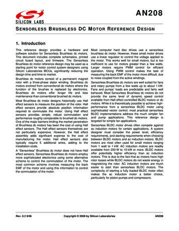
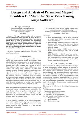
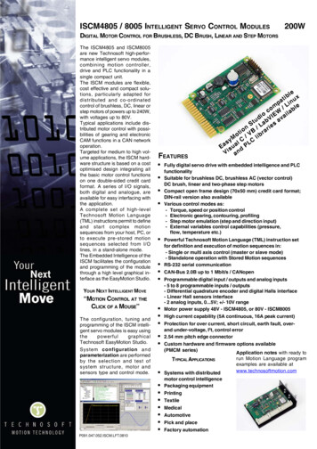
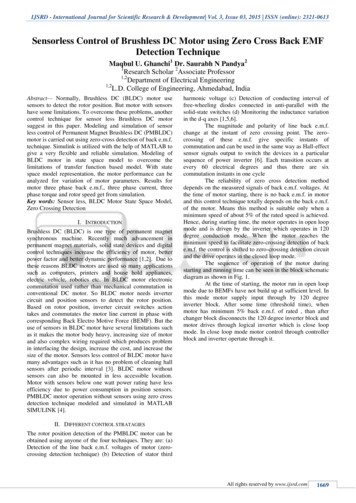
3. Matlab Simulink Modelingand Boost converters as well as acquiring accurate speedcontrol of the BLDC motor. In the following sections, first,the method of the control of the speed in DC motor will beexplained in detail using the model in MATLAB Simulinkand dSPACE. Afterwards, an explanation will be given ofthe experimental setup that uses the Simulink-dSPACEconnection to run the Boost and Buck converters with twodifferent switches (GaN and SiC) so that the BLDC motorstarts rotating periodically. In the end, all the results will begathered and the performance of GaN and SiC in Boost andBuck converters will be compared to determine which ismore suited for accurate speed control of the BLDC motor[8].The speed control of the Buck and Boost converters wasperformed in MATLAB Simulink. The dSPACE system wasrequired in order to convert the analog signals from theBLDC motor to digital signals so that Simulink can processthem. The dSPACE system was composed of the DS1104R&D Controller Board, CP1104 Connector Panel, and theControlDesk software.3.1. The Reference SpeedThe design focus of the Simulink model was torepeatedly vary the speed of the motor at different levels forspecific time periods. A pulse generator block and a steppedsystem were considered, but they are not able to fulfill therequirements. Using a repeating sequence, the motor is set toincrease the speed in ten second intervals followed by a 0.1sdelay before incrementing in speed. This delay allows timefor the motor to reach the next specified speed level. Figure1. shows the initial interval is set to 0 revolutions per minute(rpm) and it then increments from 100 to 200 to 300 rpm andthen back to zero before the sequence repeats. The goal ofthis paper was to make the control of the reference input verysimple and direct which is the advantage that the repeatingsequence was able to provide.2. Converters and Motor ChoiseIn this project to supply the DC voltage for the BLDCmotor, Buck and Boost converters are chosen to help themotor run precisely based on the time period and designedmodel.2.1. Converter ChoiceThe Boost converter has advantages such as thecapability for giving high output voltage, low operating dutycycle, and a lower MOSFET voltage. However, it generatesgreat heat and makes a significant amount of noise whenoperating [9].Buck converter has great power efficiency, but makeshigh voltage ripples, generates high peak current, and highflux density [10].For our purpose, Buck and Boost converters are moreadvantageous over other topologies because they provide uswith a straight-forward method of speed control. The Buckconverter stepping down the voltage and the Boost converterstepping up the voltage facilitates the speed control of themotor, as explained in the next main section. The voltage andspeed are proportionally related to each other in the motor,so varying the voltage allows us to directly vary the speed[11, 12]. If we were to consider a Flyback or a Forwardconverter configuration, a more complex method of controlwould be required. In their configurations, they use atransformer so core losses would be introduced as well,further complicating the transistors comparison. Overall, theBuck and Boost converters allow the accuracy of thecomparison to be prioritized.Figure 1. Reference input in the Simulink model for both Buckand Boost converters3.2. The Speed Conversion in dSPACEFigure 2. shows a series of gain blocks which areextracted from dSPACE datasheet that convert the deltaposition to the motor’s actual speed in (rpm) [15]. Thedirection of the motor is arbitrarily changed to clockwise andfollowing it is the conversion to speed in units of (rad/s). The“speed r/s” contains (1), where Ts is the sampling periodand Encoder Lines is the number of encoding lines used:2 (1)Speed ( rad / s ) Ts * ( Encoder Lines )The values are Ts 1ms and Encoder Lines 1000.Following this gain block is the conversion to speed in (rpm),as shown by the label in the “speed rpm” block in Figure 2.This second conversion was necessary because the motor’sspeed is based on (rpm). A single gain block could have beenused to represent the equations, but decomposing them inthis manner provides a clearer picture of what is being done.2.2. Motor ChoiceThe BLDC motor captured our interest because it ishighly applicable in our daily lives and has the potential toexpand even further. They are mainly used for devices thatneed to run continuously e.g., air conditioners, homeappliances, flywheel energy storage systems, and satellitepower systems [13, 14]. Having more flexibility in its speedcontrol and using more efficient transistors would makeBLDC motors applicable outside of this area. For example,one could start looking into drones that require precisecontrol of their rotors and other devices that have sensitivecontrol. By comparing GaN and SiC transistors in Buck andBoost converters, one can learn how much more effectiveone transistor would be over the other. This can helpcontribute to expanding the applications of BLDC motors.71
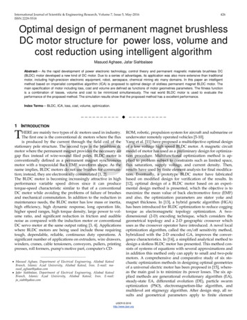
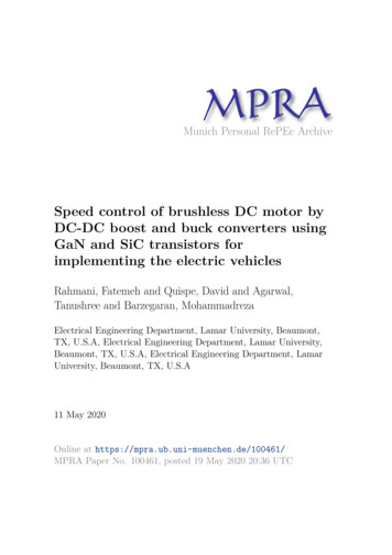
Figure 2. Calculating the speed of the motor by using gain blocks.This applies to both convertersFigure 3. The Simulink model for the Buck converter. TheEncoder Master Setup block is required for the model to runbecause it sets the channel specifications3.3. Buck and Boost Converter ModelsIn order to keep the motor’s speed as uniform as possible,Hysteresis speed control is used to keep the speed close tothe reference. Based on (2) for Buck converter and (3) forBoost converter and (4) as a relationship between speed andvoltage, the conclusion is that when the voltage is controlledor changed, consequently the speed will be controlled in thesame way. In the following eqs. (2) up to (4), D is the dutycycle, Vout is the output voltage, Vin is the input voltage.(2)Vout Vin * DVin(3)1 D(4)Ee k E * In reality, Vout and Vin refer to the speed of Hysteresisspeed controller and actual comparison speed, respectively.One of the advantages of using Hysteresis is the directcontrol in specifying the error limits to reduce the ripples asmuch as possible. To ensure that the GaN and SiCcomparison is accurate, the error bandwidth is specified tobe only 20 rpm. In doing so, significant switching losses areavoided that would occur by making the bandwidth smaller.The GaN transistor is capable of operating at high switchingspeeds, but the unbiased comparison was prioritized.The Buck and Boost converters are shown in Figure 3.and Figure 4., respectively. In both models, the actual motorspeed is compared to the reference input using the sum blockand the output is then sent to the relay where Hysteresis isused. The relay outputs a one if it detected that thecomparison passed the positive threshold, and it outputs azero if the comparison passed the negative threshold. Thisinformation is sent to the DS1104DAC C2 block whichconverts the Simulink digital signals to analog signals for themotor to understand. So if the motor’s speed was greater thanthe reference speed by more than 10 (rpm), then the relayoutputs a zero to tell the BLDC motor to decrease in speed.Similarly, if the speed is less than the reference speed, thenthe BLDC motor increases in speed. For futureimprovements of our models, a PID controller will beconsidered because it would make the models more concise.This idea is not implemented at this time because it wouldbring more complexity to the control when the focus is toprioritize the accuracy of the comparison. From thecomparison results, it can be determined which transistor toprioritize for further improvement in the control, hence thefuture consideration of a PID controller.Vout Figure 4. The Simulink model for the Boost converter. TheEncoder Master Setup block is also required here4. Experimental SetupAfter making the model of the simulation, theexperimental setup is created in order to use the simulationto run the BLDC motor. In order to make a connectionbetween the simulation in MATLAB Simulink and dSPACEis used to run the simulation and send the desirablepulse to the gate of the transistor of Buck or Boost converter.These converters are also connected to Brushless DC motorand by applying a DC voltage source, the speed of this motorwill be controlled.As mentioned in previous sections, the goal of thisproject is using Buck and Boost converters with two differentswitches (GaN and SiC transistors) to control the speed ofBrushless DC motor. Based on the comparison between SiCand GaN performances in the Introduction section, betteroutput results and efficiency with Buck or Boost converterare expected using the GaN transistor. In the followingsections, the experimental setup will be discussed andeventually, the output results, and the efficiency of the Buckand Boost converters using two different switches will becompared.4.1. Required Components to Make the DC-DC ConvereterThe important difference between the Buck and Boostconverters is applying the DC voltage using different DCvoltage sources. In the Boost converter, a high inrush currentoccurs when starting the BLDC motor, so a variable DCvoltage source is recommended. Figure 5(a). shows that inthe variable DC power source, the specific inrush current andthe best input voltage are determined using coding inMATLAB. Conversely, the Buck converter is able to workwith a regular DC voltage source at the range of 15 (V) asshown in Figure 5(b).72
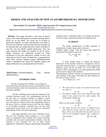
(a)(b)Figure 6. (a) Boost and (b) Buck converter circuit design usingthe GaN and SiC switches4.3. Output Results of Boost and Buck ConverterThe output parameters of two converters with GaN andSiC transistors have to be checked to verify that theseconverters perform well to control the speed of Brushless DCmotor. Boost converter should have an increase in the outputvoltage and Buck converter should decrease the outputvoltage. Based on Table 2., the Boost converter increases thevoltage from 2.8 2.9(V) to 4.7 5.2(V), and the decrease inBuck converter is from 15(V) to 4.7 5.3(V). Boost converterincreases more by using the GaN switch than the SiC switch.Similarly, the GaN switch has better performance than theSiC switch in the Buck converter because the output voltagereduces more.(b)Figure 5. These are the different DC power sources used for theBoost and Buck convertersThe other components that make the Buck and Boostconverters using GaN and SiC switches are shown in Table1.Table 1. Required components to make the converters100μF, 50 (V) Capacitor2μH InductorSiC CREEGaN transphormC2M0080120TPH3206PSB1N4001 DiodeAs shown Figure 6(a). and (b)., the Buck and Boostconverters are created based on the presented model of theseconverters. GaN and SiC transistors are exchanged in eachconverter to test the circuit and obtain the output results.Increasing the voltage4.2. Circuit DesignTable 2. Comparison of output parameters in boost and buckconverterBoost converterGaNSiCIin 2 (A)Iin 1.96 (A)Vin 2.9 (V)Vin 2.8 (V)Iout 0.82 (A)Iout 0.8 (A)Vout 5.2 (V)Vout 4.7 (V)Decreasing the voltageBuck converterGaNIin 0.52 (A)Vin 15 (V)Iout 1.3 (A)Vout 4.7 (V)SiCIin 0.54 (A)Vin 15 (V)Iout 1.1 (A)Vout 5.3 (V)The efficiency of the Boost and Buck converters arecalculated in Table 3. Comparing the output parametersbetween GaN and SiC transistors, the Boost and Buckconverters with GaN have better efficiency (74% and 78%)than using SiC in these converters (69% and 71%).Table 3. Comparison of Efficiencies Between Boost and BuckConverters with Two Different SwitchesThe Efficiency of Boost ConverterGaN TransistorSiC Transistor74%69%The Efficiency of Buck ConverterGaN TransistorSiC Transistor78%71%(a)4.4. Speed Control of Brushless DC MotorAfter checking the accuracy of the converters, they areready to supply DC voltage for the BLDC motor. Thecomparison pulse between the speed reference and the actualmotor speed is sent to the Hysteresis speed controller. Next,the output of the Hysteresis controller sends the desirable73
speed pulse to the gate of the GaN or SiC transistor in theconverters. After this procedure, the BLDC motor startsrotating based on the time period. It means that for the first10s, the motor does not have any rotation, but after 10s thespeed increases to 100 rpm and then 200 rpm and finally 300rpm (which is the fastest speed used in this project). Figure7. shows that these scopes come from three importantoutputs of the Simulink modeling, and when the motor isworking, each scope has an individual scheme.(c)Stepped-Speed referenceFigure 8. The output of the reference speed and dSPACE speed(scope 1 and 2 on dSPACE screen) in Buck and Boost convertersat different speed (a) 100rpm, (b) 200rpm, (c) 300rpmSpeed of dSPACE forcomparisonAs mentioned before, the scope 3 shown on dSPACE,which is the output of the Hysteresis speed controller inBoost converter, is the same as the scheme of the scope 3 inBuck converter. Although, using different switches (GaNand SiC) does influence the output of the hysteresis speedcontroller. Figure 9. shows the difference of the scope 3schemes between GaN and SiC switches at 210 rpm speed inBoost or Buck converter. Furthermore, GaN is used in theapplication with high frequency and the time period isshorter than the time period of the SiC waveform. Hence,using GaN switch in the converter helps to obtain accurateand better speed to control the speed of Brushless DC motor.The output of Hysteresisspeed controller and inputpulse of the switch of theconverterFigure 7. Introducing of three important scopes which are used inMatlab Simulink and dSPACEAlthough the three scopes above show different schemesindividually, the results shown on these scopes for Boost andBuck converters to control the speed of Brushless DC motorare the same. In other words, both converters provide enoughvoltage for running the motor, and they are able to increasethe speed of the motor properly and periodically. As( Ee k E ),mentioned before, based on the equationsuitable transferred voltage from converter can be changedto the proper speed to run the DC motor. In Figure 8., theschemes for scope 1 and 2 on the dSPACE screen in Boostconverter are shown at different speeds (100, 200, and 300rpm), and they are the same for the scopes in the Buckconverter. Moreover, using GaN and SiC transistors does nothave any effect on the results of scope 1 and 2.(GaN)Buck orBoostconverter(a)(SiC)Figure 9. The output of the Hysteresis speed controller (scope 3on dSPACE screen) in Buck or Boost converters at 210 rpm5. Conclusions(b)A focus on the speed control of BLDC motors needs tobe prioritized in order to expand its applications. Areas thatrequire sensitive control or energy-efficiency are the nextstep for BLDC motors which can be made possible through74
the use of more efficient transistors in DC-DC Buck andBoost converters. The experiment described in this paperwas designed to accurately compare the output parameters ofthe converters when GaN and SiC switches were used inboth. To do this, models were made in MATLAB Simulinkconnected to a dSPACE system which was connected to theconverters and the BLDC motor. The models used a directmethod of speed control with Hysteresis in order to make thecomparison accurate. Ultimately, the experiment showedthat a GaN transistor allows for both types of converters toperform more efficiently than a SiC transistor. In futureexperiments, more complex methods of speed control will beconsidered when using the GaN transistor in order to makethe control more precise.References[1] D. K. Saini, "Gallium nitride: Analysis of physical propertiesand performance in high-frequency power electronic circuits,"2015.[2] S. Roberts, DC/DC book of knowledge: Practical tips for theUser: Recom, 2015.[3] P. Vinciarelli, "Point of load sine amplitude converters andmethods," ed: Google Patents, 2006.[4] Q. Zhao and F. C. Lee, "High-efficiency, high step-up DC-DCconverters," IEEE Transactions on Power Electronics, vol. 18,pp. 65-73, 2003.[5] S. López, U. Koç, E. Bakker, and J. Rahmani, "Optimizationof Lift Gas Allocation using Evolutionary Algorithms," 2019.[6] N. A. Golilarz, N. Robert, J. Addeh, and A. Salehpour,"Translation Invariant Wavelet based Noise Reduction using aNew Smooth Non-linear Improved Thresholding Function,"CRPASE, vol. 3, pp. 104-108, 2017.[7] S. S. Mirjavadi, M. Forsat, M. Nikookar, M. R. Barati, and A.Hamouda, "Nonlinear forced vibrations of sandwich smartnanobeams with two-phase piezo-magnetic face sheets," TheEuropean Physical Journal Plus, vol. 134, p. 508, 2019.[8] M.-M. Naddaf-Sh, S. Naddaf-Sh, H. Zargaradeh, S. M. Zahiri,M. Dalton, G. Elpers, et al., "Next-Generation of Weld QualityAssessment Using Deep Learning and Digital Radiography."[9] N. Fahimi, M. R. Chalaki, M. A. Baferani, M. R. Tajik, and A.A. Shayegani, "Investigating the failures of defected siliconrubber insulators in salt-fog chamber," in 2018 IEEE TexasPower and Energy Conference (TPEC), 2018, pp. 1-6.[10] A. Elasser and T. P. Chow, "Silicon carbide benefits andadvantages for power electronics circuits and systems,"Proceedings of the IEEE, vol. 90, pp. 969-986, 2002.[11] Renesas, "BLDC Motor Basics: Understanding the principleand application of high efficiency motors."[12] F. Rahmani, F. Razaghian, and A. Kashaninia, "NovelApproach to Design of a Class-EJ Power Amplifier UsingHigh Power Technology," World Academy of Science,Engineering and Technology, International Journal nication Engineering, vol. 9, pp. 541-546, 2015.[13] R. ÇELİKEL and M. ÖZDEMİR, "Control of a Three-PhaseBoost Rectifier for High-Speed BLDC Generators Used inFlywheel Energy Storage System."[14] Daycounter, "Boost Switching Converter Design Equations,"2016.[15] D. R. Board and D. Controller, "Hardware Installation andConfiguration," ed: CRC Press, Release, 2004.75
Electrical Engineering Department, Lamar University, Beaumont, TX, U.S.A Keywords Abstract Boost converter, Brushless DC motor, Buck converter, GaN transistor, SiC transistor. Significant improvements of the DC-DC converters create the straightforward method to control the speed of the DC motor. One of the important DC motors is the Brushless DC