Transcription
International Journal of Engineering Research & Technology (IJERT)ISSN: 2278-0181Vol. 6 Issue 04, April-2017Published by :http://www.ijert.orgDesign and Analysis of Permanent MagnetBrushless DC Motor for Solar Vehicle usingAnsys SoftwareMr. Vipin Kumar SinghInstrumentation and Control EngineeringSant Longowal InstituteFor Engineeringand Technology,LongowalPunjab,IndiaAbstract—This paper presents design and performanceanalysis of Permanent magnet Brushless DC motor of 1.5 KWused in solar vehicle and hybrid electric vehicle. Finite elementmethod (FEM) is used for determining the performancecharacteristics of motor. Permanent magnet brushless DCmotor, design and its dynamic performance analysis is done onANSYS/RM Expert and then its electromagnetic studies hasdone on ANSYS/Maxwell 3D.In last motor is analyze by varyingthe lead angle in control circuit.Keywords- Permanent magnet brushless DC motor, FEMmethod , Ansys software.I.INTRODUCTIONThe power sector experienced its largest annual increase incapacity ever, with significant growth in all regions. Windand solar PV had record additions for the second consecutiveyear according to global status report 2016. Developingcountries (e.g., Kenya, Uganda and Tanzania in Africa;China, India and Nepal in Asia; Brazil and Guyana in LatinAmerica) are seeing rapid expansion of small-scalerenewable systems, including renewables-based mini-grids,to provide electricity for people living far from the grid.India’s current solar power installed capacity is 4879 MW.To promote electricity generation using solar energyGovernment of India launched Jawaharlal Nehru NationalSolar Mission in January 2010. The objective is to achievelarge-scale deployment of Solar Energy Systems and also toassist domestic production of critical raw materials,components and products to achieve grid parity by 2022.There are number of advantages of Electric vehicle overconventional internal combustion energy automobiles. Byusing Electric vehicle air pollution and green houseemission effect can be reduced with large scale.Dependency on non-renewable energy sources can bedecreased, which are limited in nature.A BLDC motor is considered to be a high performancemotor that is capable of providing large amounts of torqueover a vast speed range [4]. BLDC motors do not havebrushes (hence the name “brushless DC”) and must beelectronically commutated.IJERTV6IS040795Prof. Sanjay Marwaha, and Mr. Ashish Kumar SinghInstrumentation and Control EngineeringSant Longowal Institute of Engineering and Technology,Longowal, Punjab, IndiaAdvantages High Speed Operation – A BLDC motor can operateat speeds above 10,000 rpm under loaded andunloaded conditions. Responsiveness & Quick Acceleration – Inner rotorBrushless DC motors have low rotor inertia,allowing them to accelerate, decelerate, and reversedirection quickly. High Power Density – BLDC motors have thehighest running torque per cubic inch of any DCmotor. High Reliability – BLDC motors do not havebrushes, meaning they are more reliable and havelife expectancies of over 10,000 hours. This resultsin fewer instances of replacement or repair and lessoverall down time for your project.II.FINITE ELEMENT METHODThere are number of techniques which have been developedto solve electromagnetic related problems not amenable toexact solution.The Finite element method is used to convertthe complex partial differential equation into nonlinearalgebric equation The finite element method can be appliedto the vector Helmholtz wave equation, which is derived fromthe Maxwell’s equations, or it can be derived from a scalarvector potential formulation of the fields.There are variety ofcommercial geometrical modelling tools to accurately modelany three–dimensional geometry and to generate the requiredmesh with any kind of elements such as triangles,tetragonalsand hexagonals[2].FEM involves the following for the solving a boundary valueproblem:i) Discretization of the domainii) Derivation of the element equationsiii) Assembly of the elementsiv) Solutions of the system equations.The field analysis using FEM has three stepsi.Preprocessing stageii.Processor stageiii.Postprocessor stagewww.ijert.org(This work is licensed under a Creative Commons Attribution 4.0 International License.)1215
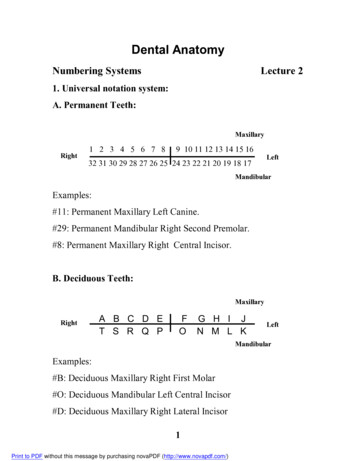
International Journal of Engineering Research & Technology (IJERT)ISSN: 2278-0181Vol. 6 Issue 04, April-2017Published by :http://www.ijert.orgIII.BASIC MATHMETICAL FORMULAS USED INELECTROMAGNETIC FIELDIn magnetic field numbers of quantities are used. They areinterrelated with each other. Magnetic flux (ø) in magneticfield is very similar to electric current (I) in electric field.Magnetic flux is related with magnetic field density (B) asØ B.A(1)Here A is the area of the magnetic flux path. Magnetic fluxunit is weber and the unit of magnetic field density isweber/m².Magnetic flux can be calculated with magneto-motive force(F) and reluctance(R) of the path.F NI(2)Where N is the number of turns used and I is the current flowthrough the coil. ThenØ F/R(3)Using equation (2) equation (3) can be representedØ NI/R(4)Reluctance of the magnetic path is depends on length of themagnetic path (l), permeability of magnetic material(µ) andarea of flux flowing path .R l/µA(5)Magneto-motive force (F) in magnetic circuit is similar toelectromotive force (E) in electric circuit. Magnetic fielddensity (B) is similar to electric field density (D).Maxwell’s equations represent one of the most elegant andconcise way to explain the fundamentals of the electricity andmagnetism. With the help of Maxwell’s equations one candevelop most of the working relationship in static or timevarying electromagnetic field.The differential for of maxwell’s equations for the timevarying condition is given below.(1)(2) .D ƪv .B 0(3) X E -ðB/ðt(4) X H J ðD/ðtCogging torque is defined as the unwanted torque that isproduced in the PM BLDC motor due to the interaction of therotor magnets and slots and poles of the machine. The coggingtorque reduces the average torque produced by the machineand introduces unwanted torque ripple in the PM BLDCmotor. The expression for the cogging torque is given byTcog -½ Øg2dR/dƟ(7)Where Øg is the air gap flux and dR/dƟ is the change in airgap reluctance with respect rotor angle. It is important to notethat most techniques used to reduce the cogging torque willreduce the effective back EMF and hence the resulting mutualtorque production.B. MOTOR DESIGNThe basic design of the motor is done in RMxperttm of AnsysMaxwell and Finite Element Method has been done inMaxwell 2D. Parameters given in the table are used as aninput to the software.a) RMxperttm- It offers numerous machine-specific, templatebased interface for induction, synchronous and electronicallyand brush commutated machines. These templates allow toeasily enter design parameters and to evaluate design tradeoffs early in the process. Critical performance data such astorque versus speed, power loss, flux in the air gap, powerfactor and efficiency can be quickly calculated. The modeldesigned in RMxpert can be easily exported in Maxwellproject (2D/3D) for Finite Element Method andelectromagnetic transient analysis.b) STATOR DESIGN- Stator is the static part of any motoror generator. Table 1 shows the parameters of analysissetup for design. On the basis of table 1 parameters thestator data will be mentioned in table 2[1].Table.1SR.NO.PARAMETERVALUE1Rated power(w)15002Rated voltage(volt)1003Rated speed(rpm)30004No. of pole45Frictional loss(W)106Windage loss(W)2Table 2A. BASICS OF MOTOR STRUCTURE SPECIFICATIONTorque (T) generated by BLDC motor is depends on rotordiameter (D) and axial length of the rotor (L) .It can berepresented asT KD²Linterpreted that if the axial length is double, Torque will alsodouble at constant power [3,4].(6)With equation (6) it can be understood that the Torquegenerated by a motor is mainly depends on diameter of rotor.As the diameter of rotor increases circumference areaavailability for permanent magnet increases. It can beSR.NO.1234567PARAMETERNumber of slotOuterDiameter(mm)Inner Diameter(mm)Length of statorcore(mm)VALUE12120Number of slotsStacking factorConductor per slot12.951206255Stator in Figure 1 is constructed with the help of table 2.IJERTV6IS040795www.ijert.org(This work is licensed under a Creative Commons Attribution 4.0 International License.)1216
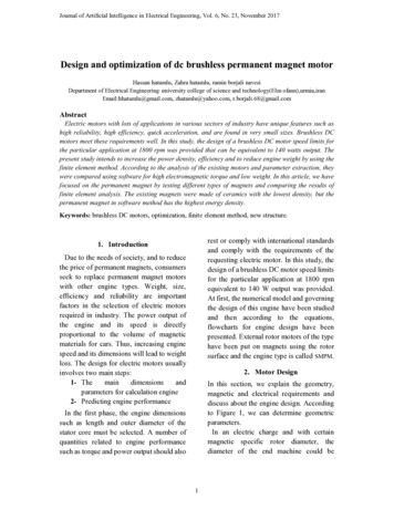
International Journal of Engineering Research & Technology (IJERT)ISSN: 2278-0181Vol. 6 Issue 04, April-2017Published by :http://www.ijert.orgFig.3. Rotor GeometryRotor parameters are given in table Table 4Table.4Fig.1. Stator geometryc)Slot parameters- Shape and dimensions of the slot arementioned in figure 2 and table 3.Sr.No.12PARAMETERMinimum air gap(mm)Inner Diameter(mm)VALUE11834Outer Diameter(mm)Length of rotor(mm)60555Type of steelSteel 100867EmbraceThickness of magnet(mm).85489Magnet TypeWidth of Magnet(mm)NdFe3536.73Fig.2.Slot DimensionTABLE 3. Slot DimensionSr. 4Bs1(mm)11.415Bs2(mm)16.83d)Figure 4 cross-section view of BLDC motor.Table.5. other important parameter for motorROTOR DESIGN- It is the moving component of theelectromagnetic system in the electric motor or generator. Forthe rotor permanent magnet pole many shapes are given inRMxprt but the given figure 3 is TERResidual Flux Density(Tesla)Coercive Force(A/m)Maximum Energy Density(kj/m3)Average Input Current(A)RMS Armature current(A)ArmatureCurrentDensity(A/mm2)Frictional and Windage Loss(W)Iron core Loss(W)Armature Copper Loss(W)Transistor Loss(W)Diode Loss(W)Total Loss(W)Output Power(W)www.ijert.org(This work is licensed under a Creative Commons Attribution 4.0 International 38.00212710.3868.5264.6994.58531499.31217
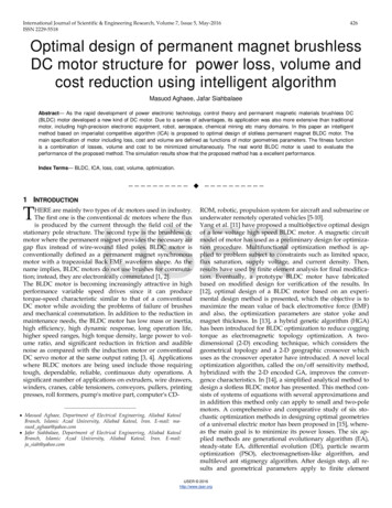
International Journal of Engineering Research & Technology (IJERT)ISSN: 2278-0181Vol. 6 Issue 04, April-2017Published by :http://www.ijert.org1415161718192021Input Power(W)EfficiencyRated Speed(RPM)Rated Torque(N-m)Maximum Output Power(W)Air Gap Ampere Turn(A.T)Magnet Ampere Turn(A.T)Leakage Flux 8.11Some important plots ore given below when the simulation ofthe model was executed in the RMxpert.Fig.8. Air Gap Flux Density vs Electric DegreeFig.5. Efficiency vs speedFig.9. Winding Current under load vs electric degreeIV. MAXWELL 2D SIMULATIONMotor design create on RMxprt is export in Maxwell 2D.Thissoftware is used to create meshing for FEA [2].Electromagnetic analysis is done with the help of Maxwell2D.Motor in Maxwell 2D is shown in fig.10.Fig.6.Torque vs SpeedFig.10. motor in Maxwell 2DThere are some analysis are done on the basis of simulationin Maxwell 2D .Fig 11 shows the mesh formation at specifictime of rotor position.Fig.7. Cogging Torque vs Electric DegreeIJERTV6IS040795www.ijert.org(This work is licensed under a Creative Commons Attribution 4.0 International License.)1218
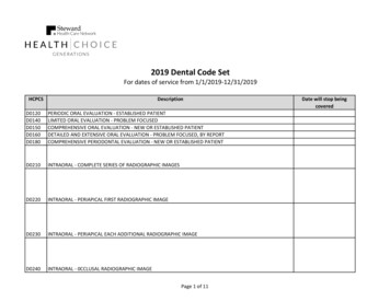
International Journal of Engineering Research & Technology (IJERT)ISSN: 2278-0181Vol. 6 Issue 04, April-2017Published by :http://www.ijert.orgFig.14. Motor torque at 0 degree lead angleFig.11. Mesh Formation in Maxwell 2DIn fig.12. magnetic field density is shown at specific time ofrotor position.V. Analysis after increasing lead angle of control circuitAbove motor designing is done when lead angle is taken 0degree. For improving motor performance lead angle isvarying and the change in motor performance is analyzed.After changing motor lead angle efficiency of motor isincreased. Lead angle shows how early the phase voltage isinjected. When lead angle increases, phase current excites theearlier winding. As each phase current has the same phaseangle as each phase back emf, the BLDC motor gives thegiven torque demand while needing a lower demand currentand achieves higher efficiency as copper loss is reduced.Table 6 shows some important parameter when lead angle isvarying from 0 degree to 30 degree.TABLE.6Sr.No.1PARAMETERResidual FluxDensity(Tesla)Coercive Force(A/m)VALUE1.23Maximum EnergyDensity(kj/m3)273.674Average Input Current(A)15.915RMS Armature current(A)14.046Armature CurrentDensity(A/mm2).5287Frictional and WindageLoss(W)12.93168Iron core Loss(W).00249Armature Copper Loss(W)9.2910Transistor Loss(W)66.72511Diode Loss(W)2.79412Total Loss(W)91.74713Output Power(W)1499.5414Input Power(W)1591.2915Efficiency94.23416Rated Speed(RPM)3170.9617Rated Torque(N-m)4.5118Maximum Output Power(W)7397.9219Air Gap Ampere Turn(A.T)573.5620Magnet Ampere Turn(A.T)-1218.12Fig.12. Magnetic Field Density at specific rotor positionFig.13. Magnetic Field Intensity at specific rotor position.Motor torque generated by the motor at different time isshown in Fig.14IJERTV6IS0407953www.ijert.org(This work is licensed under a Creative Commons Attribution 4.0 International License.)8900001219
Published by :http://www.ijert.orgInternational Journal of Engineering Research & Technology (IJERT)ISSN: 2278-0181Vol. 6 Issue 04, April-2017On lead angle 30 degree the torque produced by motor isshown in fig.15Fig.15. Motor Torque at 30 degree lead angleVI. CONCLUSIONThis paper represent the basic design idea of PermanentBrushless DC Motor. First of all basics of magnetic circuit isexplain and then required basic equation used inelectromagnetic field is describes. In this paper PermanentBLDC motor used in solar vehicle of 1500W and 3000 rpm isdesign. This paper shows that motor gives considerably goodefficiency at rated torque and at rated speed.Motor is designin RMxprt and the its electromagnetic field analysis is doneon Maxwell 2D. After designing of motor, analysis is doneby varying the lead angle of control circuit. It is seen thatwhen the lead angle is increased from 0 degree to 30 degreeefficiency of the Permanent BLDC Motor is increased. Byincreasing lead angle rated speed of motor is increased.Increase in efficiency is achieved at the cost of decrease inrated torque and increase in ripple in torque.VII. REFERENCE[1] Durmus Uygun, Selim Solmaz, “Design and Dynamic Study ofa 6 kW External Rotor Permanent Magnet Brushless DC Motorfor Electric Drivetrains”, 2015 IEEE 5th InternationalConference on Power Engineering, Energy and ElectricalDrives.[2] Nishtha Shrivastava, Anil Brahmin, “Design of 3-Phase BLDCMotor for Electric Vehicle Application by Using FiniteElement Simulation”, International Journal of EmergingTechnology and Advanced Engineering, Volume 4, Issue 1,January 2014.[3] Sanjana Ahmed, Ahmed Hosne Zenan, Mosaddequr Rahman,“A Two-Seater Light-Weight Solar Powered Clean Car:Preliminary Design and Economic Analysis”.[4] Basics of BLDC Motor (internet data).[5] Malik Sameeullah, Sunita Chandel, “ Design and Analysis ofSolar Electric Rickshaw: A Green Transport Model”.2016IEEE.[6] Mehdi Ouada, M.S Meridjet , M Saad Saoud, Talbi N,“Increase Efficiency of Photovoltaic Pumping System BasedBLDC Motor Using Fuzzy Logic MPPT Control”, WSEASTRANSACTIONS on POWER SYSTEMS, Issue 3, Volume 8,July 2013.IJERTV6IS040795www.ijert.org(This work is licensed under a Creative Commons Attribution 4.0 International License.)1220
characteristics of motor. Permanent magnet brushless DC motor, design and its dynamic performance analysis is done on ANSYS/RM Expert and then its electromagnetic studies has done on ANSYS/Maxwell 3D.In last motor is analyze by varying the lead angle in control circuit. Keywords- highest running Permanent magnet brushless DC motor, FEM method .File Size: 650KBAuthor: Vipin Kumar Singh, Sanjay Marwaha, Ashish Kumar SinghPage Count: 6