Transcription
AN208S ENSO RLE S S B RUSHLESS DC M O T O R R E F E R E NC E D ESIGN1. IntroductionThis reference design provides a hardware andsoftware solution for Sensorless Brushless dc motors.This document includes complete schematics, printedcircuit board layout, and firmware. The SensorlessBrushless dc motor reference design may be used as astarting point for motor control system designers usingSilicon Laboratories MCUs, significantly reducing thedesign time and time to market.Brushless dc motors consist of a permanent magnetrotor with a three-phase stator winding. Brushless dcmotors evolved from conventional dc motors where thefunction of the brushes is replaced by electronics.Brushless dc motors offer longer life and lessmaintenance than conventional brushed dc motors.Most Brushless dc motor designs historically use Halleffect sensors to measure the position of the rotor. Halleffect sensors provide absolute position informationrequired to commutate the motor. Using Hall effectsensors provides simple, robust commutation andperformance roughly comparable to brushed dc motors.One of the major barriers limiting the market penetrationof Brushless dc motors has been the cost of using Halleffect sensors. The Hall effect sensors themselves arenot particularly expensive. However, the Hall effectassembly adds significant expense to the cost ofmanufacturing the motor. Hall effect sensors alsotypically require 5 additional wires, adding to theinstallation costs.A “Sensorless” Brushless dc motor does not have Halleffect sensors. Sensorless Brushless dc motors employmore sophisticated electronics using some alternativescheme to control the commutation of the motor. Themost common scheme involves measuring the backEMF of the motor and using this information to controlthe commutation of the motor. Rev. 0.2 9/06Most computer hard disc drives use a sensorlessbrushless dc motor. However, these small motor drivesuse a linear regulator to control the voltage applied tothe motor. This works well for small motors, but is tooinefficient to use for motors greater than a few watts.Larger motors require PWM control for efficientoperation. Using PWM control makes the task ofmeasuring the back EMF of the motor more difficult, dueto noise coupled from the active windings.Sensorless Brushless dc motors are well suited for fansand rotary pumps from a few watts up to about 1 kW.Fans and pumps’ loads are predictable and fairly wellbehaved. Most Sensorless Brushless dc motors do notprovide the same level of dynamic speed controlavailable from Hall effect controlled BLDC motors or dcmotors. While it is theoretically possible to achieve highperformance from a sensorless BLDC motor usingsophisticated vector control, most practical sensorlessBLDC implementations address the much simpler fanand pump applications. This reference design istargeted for simple fan applications.Sensorless BLDC motor drives often compete againstac induction motors for certain applications. A systemdesigner must consider the power level, efficiencyrequirements, and starting requirements when choosingbetween BLDC motors and ac induction motors. BLDCmotors are most often used for small motors rangingfrom 1 watt to 1 kW. AC induction motors are readilyavailable from 250 W to 10 kW or more. BLDC motorsoffer potentially higher efficiency than ac inductionmotors. This is due to the fact that ac motors have highrotor losses while BLDC motors do not waste energy inmagnetizing the rotor. AC induction motors are mucheasier to start than sensorless BLDC motors. Thecomplexity of starting a fully loaded BLDC motor oftenmakes the ac induction motor a better choice,particularly for piston pumps and compressors.Copyright 2006 by Silicon LaboratoriesAN208
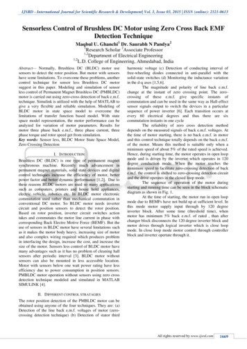
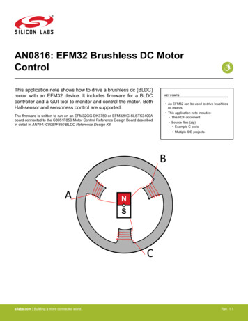
AN208TorqueMotor12 VoltaVge10V8V6V4VLineLineLoadVariable VoltageConstant VoltageSpeedFigure 3. Stepper Motor CharacteristicsFigure 1. DC Motor CharacteristicsThe characteristics of a stepper motor are quitedifferent. The motor current in a stepper motor is notproportional to the load torque. The motor windingresistance typically limits the current in a stepper motor.The motor winding resistance of a stepper motor isnormally an order of magnitude higher than a BLDCmotor. An ideal model for a stepper motor is shown inFigure 2. RW -BackEMFThe performance of the stepper motor may be improvedusing a variable voltage drive. By increasing the voltageapplied to the stepper motor in proportion to the velocity,the available torque will remain constant and the fancan be driven to a higher velocity before stalling asshown in Figure 3.A BLDC motor can also be considered as an unusualstepper motor. A 4-pole 12 V BLDC motor is functionallyequivalent to a 12-step per revolution stepper motorwith a voltage rating of about 1 V. A typical Steppermotor has a much higher step count, higher voltage,and higher resistance. A typical hybrid permanentmagnet stepper motor has a step angle of 1.8º, or 200steps per revolution. A 12 V stepper motor might have aresistance of 30 , compared to less than 1 for asimilar size BLDC motor. The stepper motor isoptimized for precise angular positioning and constantvoltage drive. The BLDC motor is optimized for Halleffect commutation and variable voltage drive.2.1. PWM Scheme-Figure 2. Stepper Motor ModelThe motor is driven with a constant voltage. When themotor is at a standstill, the back EMF is zero and thecurrent is at its maximum value. As the motor speedincreases the back EMF will increase, reducing thevoltage across the motor resistance, and the motor2stallstallSpeedVMLoadBrushless dc motors have a dual personality. To fullyunderstand Sensorless Brushless dc motor control it isnecessary to understand both dc motor characteristicsand Stepper motor characteristics. When commutatedusing Hall effect sensors, the torque speedcharacteristics of the Brushless dc motor are virtuallyidentical to a conventional dc motor. The ideal no loadspeed is a linear function of the applied voltage. Thetorque and motor current are at a maximum at zerospeed and decrease to zero at the maximum speed.The torque-speed characteristics of a dc motor areshown in Figure 1. Under ideal conditions, thecharacteristics of a sensorless BLDC motor are similar.current will decrease. The available torque for a steppermotor is proportional to the current forced through themotor windings. The available torque is at its maximumvalue when the motor is at a standstill. The availabletorque decreases as the motor speed increases. If theload torque ever exceeds the available torque the motorwill stall.Motor Current2. Theory of OperationMost Hall effect BLDC motors use a three-phase bridgeto drive the motor windings. A Three-Phase bridge isshown in Figure 4.Rev. 0.2
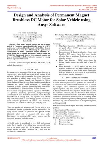
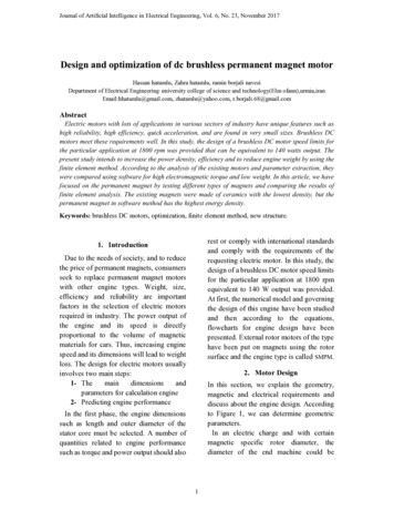
AN208BTopATopPhaseAABottomA (PWM)CTopAPhaseBBBottomPhaseCYCBottomB (ON)The most common drive method is to use blockcommutation and apply a PWM signal to only thebottom transistors as shown in Table 1. Depending onthe position of the motor and the Hall effect code, theappropriate step pattern is applied to the motor. As themotor rotates, the step pattern will increment throughthe table entries. Using this method, at any point in timethere is only one top transistor in the continuous ONstate and only one bottom transistor being driven by thePWM signal.Table 1. Low-Side PWM gure 5. Low-Side PWM Back EMFFigure 4. Three-Phase dering the motor phases, one phase is drivenhigh, one phase is being pulse-width modulated, andone phase is open. The open phase is noted in thetable. However, there is a problem using the openphase to sense the back EMF when pulse-widthmodulating only the bottom transistors.Consider the BLDC motor winding shown in Figure 5. Inthis case the motor is at the first state of thecommutation table. A pulse-width modulated signal isapplied to phase A, phase B is driven high, andphase C is open. The back EMF that we are interestedin is actually the voltage from phase C to the centerconnection labeled point Y. The problem is that thecenter of the Y connection is not a constant dc voltage.Assuming that the resistance and inductance ofwindings A and windings B are the same, the voltage atpoint Y will be halfway between phase A and phase B.The voltage at point Y will be approximately half thesupply voltage when phase A is driven low. Whenphase A is high, the center point Y will be approximatelyequal to the upper supply voltage. The voltage on theopen phase C is now the voltage at center-point Y plusthe back EMF of the motor. The voltage at phase C isalso clamped to the upper rail by the MOSFET bodydiodes in the inverter bridge. The result is a pulse widthmodulated waveform where the minimum voltage levelis equal to the back EMF of the motor. While it ispossible to filter out the PWM signal or sample thevoltage during the PWM on-time, working with thiswaveform is problematic.A better approach is to use a symmetric PWM scheme.A symmetric PWM scheme is any PWM scheme wherethe active top and bottom transistors are turned on andoff together. The simplest method is to apply identicalPWM signals to the top and bottom transistorsaccording to Table 2. This commutation table is similarto the low side PWM commutation table except that thehigh side transistors are pulse-width modulated insteadof just being turned on.Rev. 0.23
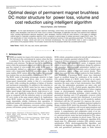
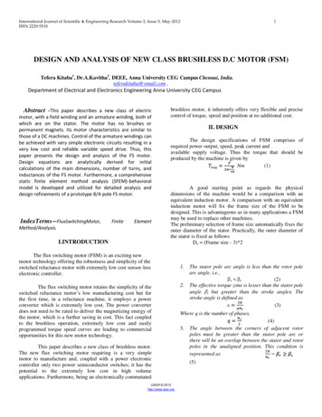
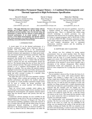
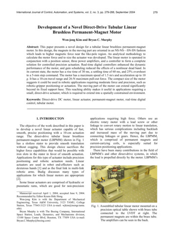
AN208Table 2. Symmetric PWM CommutationTopA0BBottomCPWMABOpenPWMBThe back EMF voltage for three different cases is shownin Table 3. If the voltage and speed are just right thevoltage ramp will be centered within the commutationperiod and the midpoint voltage will measure half of thesupply rail. If the voltage is too low or the speed is toofast the voltage ramp will be shifted up and to the right.If the voltage is too high or the speed is too slow, thevoltage ramp will be shifted down and to the left. Thefeedback loop should work to keep the mid-pointvoltage at mid-rail.PWMATable 3. Back EMF ControlCPhasePWMC1PWM PWMB2PWM3 PWMPWMAPWMC4 PWM5PWMthe motor approaches a stall condition. When using thezero-crossing time as a feedback signal, specialmeasures must be taken when a zero crossing does notfall within the measurement window.WaveformDuring the first state of Table 2, an identical PWM signalis applied to both the A bottom transistor and the B toptransistor. The result is that Phase A will go low whenPhase B goes high and visa versa. If the A and Bwindings are balanced, the center point Y will remainmid-rail even though phase A and phase B are beingpulse-width modulated. The voltage on phase C is nowroughly equal to the back EMF voltage. There may besome residual PWM noise due to the second ordereffects of unbalanced windings and capacitive coupling.However, the unwanted PWM signal is reduced by atleast an order of magnitude, as shown in Figure 6.SpeedVoltageToo FastToo LowJust RightJust RightToo SlowToo HighA (PWM)AYC(open)B (PWM)BYCFigure 6. Symmetric PWM Back EMF3.1. Safe Operating Range3. Back EMF WaveformsMost sensorless BLDC control systems use the backEMF zero crossing time as a control variable for aphase locked loop. Instead of using the zero-crossingtime, this reference design measures the back EMFvoltage at middle of the commutation period using theADC and uses the voltage measurement to control thecommutation. This method provides higher resolutionand always provides a robust feedback signal even as4When driving a Sensorless BLDC motor from a MCUthere are two output variables, the motor Voltage V andthe motor speed . Figure 7 shows the output voltageverses speed characteristics for a sensorless BLDCmotor. Three lines are labeled in Figure 7. The middleline is the ideal “no load” line with V equal to times themotor constant KE. This line represents the optimumvoltage for a perfect motor with no friction.Rev. 0.2
AN208Wmid axm ea V um l V KV K E · K E · ImE· ax-I·RmWax·Rthe negative area is permitted. If the motor speedcommand is decreased, the control system will outputvalues in the negative torque region until the operatingpoint is re-stabilized. While it is possible to prohibitoperation in the negative torque region, this mayadversely affect the stability of the control system.The safe operating area is important because it is veryeasy to exceed the limit using conventional controltechniques. If we ignore the safe operating area anduse a simple PI controller to regulate the output voltage,the control loop will output excessive voltage and thepower transistors may be damaged.miniVM Figure 7. Output Voltage and SpeedThe maximum current is normally limited by thecapability of the power transistors. The maximum boostvoltage is then the maximum inverter current times thewinding resistance. The upper line in Figure 7 is theideal voltage plus the maximum boost voltage. This linedefines the maximum bounds for safe operation. Thelower line is the ideal voltage minus the maximum boostvoltage. This line defines the minimum bounds for safeoperation. While not intuitive, it is quite possible to getan over-current condition by driving the motor with avoltage that is too low for a particular speed.VMn e poga sittiv iveeto torrq que uere regi gon ionDanger!V too highIf we drive the motor with a voltage corresponding to themaximum line, we are forcing maximum current into themotor at all times. This will provide the maximumavailable torque at all times and it is unlikely that themotor will stall. However, the no load efficiency will bevery low and cogging torque may be a problem.Cogging torque is the variation in torque caused by apulsating electromotive force. Stepper motors aredesigned to operate on the max line with low coggingtorque. Most BLDC motors are not designed for thiskind of operation. Excessive cogging torque can causevibration, noise, and stability problems.This reference design uses a novel control techniqueentitled “Constant Voltage Control with SpeedDependent Limiting”. The goal of this controlmethodology is to provide a simple and robust controlalgorithm using a single control loop while keeping theoutput speed and voltage within the Safe OperatingArea.The control technique is illustrated in Figure 9. Theinput speed control potentiometer controls the targetoperating point indicated by the dot on the ideal line. Ifthe error signal is zero, the output voltage and speedare set according to the speed potentiometer. As thespeed control is varied, the target operating point willvary along the ideal line.Danger!V too low Figure 8. Safe Operating AreaThe Safe Operating Area for the Sensorless BLDCmotor is shown in Figure 8. Above the maximum line thevoltage is dangerously too high. Below the minimum linethe voltage is dangerously too low. The area betweenthe ideal line and the max line is labeled the positivetorque region. In normal steady state operation, theoutput variables will operate in the positive torqueregion.The area below the ideal line is labeled the negativetorque region. While most simple fan and pumpapplications do not require negative torque, operation inThe bold line indicates variation in the output voltageand speed due to the error signal. A small positive errorsignal from the feedback control system will result in adecrease in speed while the voltage remains constant.The voltage will remain constant until the speed reachesthe limit set by the maximum line. If the error signal islarge enough to exceed the limit, both voltage andspeed are reduced according to the maximum limit.In a similar fashion, a small negative error signal willresult in an increase in speed. If the negative error isincreased beyond the bounds set by the minimum line,the voltage will be increased.The resulting control loop is very stable. The motor isdriven with a constant voltage, as long as the loadRev. 0.25
AN208torque and acceleration are within the bounds set by theminimum and max limits. In this region the motorbehaves like a dc motor with a constant voltage drive. Asmall increase in load torque will result in a smalldecrease in speed.oStFor large positive errors signals, the motor voltage isreduced to keep the current below the maximum limits.In this region the motor behaves as a constant currentor constant torque drive.pC mdRUNi STOP1OverCenurrt 1artCmd 1ALIGN192STARTVmaxSt&&NIG NLV A IGv TAL tFigure 10. SBLDC State Diagram-Error3.3. Alignmentid mae xm alin ErrorVM00 min maxFigure 9. Constant-Voltage with Limiting3.2. StartingOne major problem with using the back EMF to controlthe commutation of a sensorless BLDC motor is that theback EMF is not present or is too small to be useful untilthe motor is rotating at some minimum speed. Thecommon solution is to drive the BLDC motor like astepper motor to align the motor and accelerate themotor up to some nominal speed. This requires that thecontrol system have multiple modes of operation. Whileit is generally undesirable to have a control system withmultiple modes of operation, it is unavoidable in thiscase. A common pitfall of systems with multiple modesof operation is instability during the transition from onecontrol mode to another. Special considerations arerequired in the running stage to ensure system stabilityduring the transitions.The motor state diagram is shown in Figure 10. Thesystem is initially in the STOP state. Pressing the Startbutton will advance to the ALIGN state. The motor willthen advance automatically to the START and RUNstates. An over-current error will reset the motor to theSTOP state.6The alignment state consists of two stages—theAlignment Ramp and the Alignment Delay. During theAlignment Ramp, one of the motor windings is excitedby PWMing the top of one phase and the bottom ofanother phase. The PWM duty cycle is initially at zeropercent and is ramped up to 50% plus the starting boostvoltage. The voltage is increased using a linear rampwith a fixed delay time between voltage increments. Thecurrent in the motor winding will depend on the motorinductance and winding resistance. For duty cyclesbelow 50% the current will be discontinuous. Thecurrent will increase while the transistors are on anddecrease to zero after the transistors turn off as shownin Figure 11.V 50%IV50%IV 50%IFigure 11. Motor Current vs. Duty CycleThe peak and average dc current for duty cycles equalto or less than 50% can be calculated using Equation 1.The PWM duty cycle will always be above 50% whilerunning.Rev. 0.2
AN208value of 750 rpm was chosen to be one tenth of themaximum speed of the motor. The closed loopsensorless control will then operate over a 10:1 rangefrom 750 to 7500 rpm. The back EMF at 750 rpm will beone tenth of the rated voltage.VI avg I peak ---- dLEquation 1. Peak and Average CurrentFor duty cycles above 50% the current will becontinuous. Usually a higher current is desired foralignment. Above 50%, a small change in duty cycle willresult in a much large change in average dc current.The starting boost voltage is typically a very smallnumber.The second part of the alignment phase consists of asimple delay. The voltage is held constant for a period oftime. The alignment delay time should be long enoughto allow the motor to align to the excited pole position. Aone second ramp time and a two second delay timeworks well for the test motor with no fan. When using alarge fan, a time of several seconds may be required.Finding the optimal delay time requires someexperimentation.The alignment stage ensures that the motor starts froma known position. Without the alignment stage the motormight miss the first several critical commutations in thestarting acceleration ramp. If the motor does not alignduring this stage a motor stall is more likely in thestarting phase.During the alignment stage the system is in a relativelybenign state. The dc current is predictable and wellregulated. The power dissipated in the motor can becalculated from the motor winding resistance. A currentmeasurement is only needed to protect against wiringerrors.Most BLDC motors are optimized for high-speedoperation and have very limited torque in the alignmentphase. This is not too much of a problem for small fans,but it does preclude the use of sensorless control insome other applications. The torque is limited by theinverter current and motor design. Over-sizing theinverter or using a lower speed motor can increase thestarting torque.3.4. StartingDuring the starting phase the BLDC motor is driven likea stepper motor. The motor is commutated at first veryslowly and then velocity is increased linearly using alinear velocity ramp table. The voltage is also increasedin proportion to the velocity with additional boost voltageto keep the current at a constant value. The motorwinding resistance normally limits the boost voltage.The acceleration ramp table ramps the motor speedover a 30:1 range from 25 to 750 rpm. The maximumThe key to getting the motor up to 750 rpm is to use alarge enough acceleration ramp table with a sufficientlylarge ratio of minimum to maximum. A ratio of 30:1 canbe achieved using a table with only 192 bytes of data.This also permits the efficient use of an 8-bit table index.Experimental results using a smaller 16-byte table withan 8:1 range proved unsatisfactory. If the table is toosmall, the initial velocity will be too fast or the finalvelocity will be too slow.The voltage of the motor is also ramped during theacceleration phase. If the voltage were held constant atthe alignment value, the current would decrease duringthe motor acceleration. Initially the current is only limitedby the motor resistance. As the motor starts turning, theback EMF of the motor will subtract from the voltageacross the motor resistance. This results in a decreasein motor current and a corresponding decrease in theamount of available torque.Assuming the motor will accelerate in step with thecommutation period, the back EMF will be proportionalto the motor velocity and inversely proportional to themotor period. The motor voltage ramp may becalculated by dividing a constant by the value in theramp table. By increasing the voltage during theacceleration phase the motor current can be held at aconstant value. This ensures maximum available torqueduring the acceleration phase.If the motor stalls at any point, the back EMF will bezero, and the assumption of motor velocity is no longervalid. The resulting motor voltage will be too high andthe current may be much higher than expected. This isproblematic for small motors and can be disastrous forlarge motors.The solution is to monitor the dc motor current duringacceleration and to shut down if the motor current getstoo high. The back EMF is not sufficiently large to detectif the motor is moving. A current limit is not neededduring the starting phase if the motor voltage is limitedto the maximum inverter current times the motorresistance, though this will severely limit the startingtorque on all but the smallest motors.3.5. RunningThe minimum Running speed and voltage are dictatedby the starting parameters. In this example, theminimum speed is 750 rpm. The minimum voltage is10% plus the boost voltage. At the lower operatingRev. 0.27
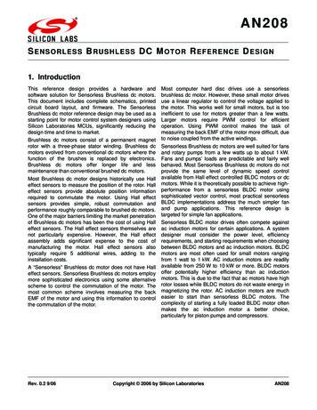
AN208point, the motor is being over-driven by a voltage that isintentionally higher than necessary for stable closedloop operation. Since the motor is being driven like astepper motor, the cogging torque and motor vibrationwill be higher in the starting phase.top starting with phase A in the least significant bit.P1.0-1.5 corresponds to A bottom, A top, B bottom,B top, C bottom, and C top respectively. This sequencefacilitates commutation using a simple pattern with theCrossbar pin skip register.3.6. Back EMF MeasurementsEach of the three output phases are connected to asimple resistive divider. The resistive divider will dividethe phase output voltage by six. This ratio permitsaccurate ADC measurements up to 19.8 volts. The 5 Vtolerant port pins offer protection against phasevoltages up to 30 Volts. The motor supply is 12 Vnominal when loaded with the motor turning at fullspeed. The unloaded voltage may climb as high as 18 Vfor the recommended wall mounted transformer.The back EMF is measured at three points, as shown inFigure 12. The midpoint voltage is the primary controlvariable for closed loop control. The two voltagemeasurements at one quarter and three fourths areused for stall detection. The current measurement isused for over current detection. The time slots arediscussed in further detail in the software description.TimeSlot 1TimeSlot 2A capacitor across the lower resistor of each dividerforms simple single-pole low-pass RC filter. Each filter istuned approximately one decade below the PWMfrequency. Three test points are provided for the scaledvoltages labeled VA, VB, and VC.TimeSlot 3run3()Sample EMFCheck for Stallrun2()Sample EMFCalculate Errorrun1()Sample EMFrun0()Sample CurrentSample PotBack EMFTimeSlot 0Figure 12. Back EMF SamplingStall detection is achieved by measuring the voltage atquarter points over two cycles. The difference betweenthe minimum and maximum of these four points is anindication of the back EMF of the motor. If the back EMFis greater than a certain value, we can deduce withreasonable certainty that the motor is indeed running. Ifthe back EMF is too small to give a usefulmeasurement, we cannot know for certain if the motor isstalled or running. Thus, the stall detection operatesonly in the running phase. The example implementationilluminates an LED when a stall condition is detected.A forth resistive divider is used to sense the voltage ofthe motor supply. This resistive divider has a ratio of oneto twelve. A test point is provided on the scaled motorsupply voltage labeled VM. A phase voltage of 12 voltswill produce voltage of 2 V on the respective ADC input,while a supply voltage of 12 V will produce a sensevoltage of 1.0 V on the VM ADC input. A differentialADC voltage measurement will be used relative to theVM ADC input. The resulting ADC reading will be asigned 16-bit value with 0x0000 corresponding to midrail.The sensorless BLDC motor reference design boardincludes a current sense resistor R25 and currentamplifier U7A. The sense resistor is a 20 m surfacemount resistor in an 1812 package. The sense resistorwas chosen for a maximum RMS current of 5 amps witha power dissipation of 500 mW. The resulting sensevoltage of only 100 mV requires amplification to achievemore than 5 bits of resolution from the 10-bit ADC.The schematic diagram for the Sensorless BLDC Motorreference design is in Appendix A. The circuit consistsof the C0851F310 Microcontroller, three-phase powerMOSFET bridge, three dual gate drivers, sense voltageresistive dividers, current amplifier, speed controlpotentiometer, two function switches, USB-UARTbridge, and voltage regulator.The current amplifier is a variation of the classicdifferential amplifier circuit. In the classic circuitconfiguration, the second resistors on the non-invertinginput would be connected to ground. In this variation,resistor R17 is connected to a 400 mV voltagereference. The 0.4 V reference compensates for thevariation in the input offset voltage of the op amp andalso keeps the output within the recommended outputvoltage range. The gain of 26 was chosen to fully utilizethe output voltage span of the amplifier allowing forvariation in the input offset voltage.Port P1 is configured as push-pull outputs and isconnected to the three dual gate drivers. The P1 portpins are sequenced, alternating between bottom andThe op amp chosen for this circuit is the LMV358. Thisis a low-voltage version of the industry standard LM358dual CMOS op amp. The second op amp in the dual4. Hardware Description8Rev. 0.2
AN208package is used for the 400 mV reference U7B. A singlezero-current calibration is used to eliminate the variationin the input offset voltage. This circuit design pensive CMOS op amp.To aid development, the sensorless BLDC referenceboard includes a USB interface. The CP2101 USBUART bridge IC is used in place of an RS232transceiver chip. The CP2101 provides USBconnectivity using virtual COM port drivers on the hostPC. The C8051F310 UART communicates with theCP2101 using conventional asynchronous serial data.Code can be developed on the C8051F310 using theprintf() and scanf() stdio library functions.5. Software DescriptionThe c code for the sensorless BLDC motor referencedesign is organized into four files:slbdc.hslbdc.cT0 ISR.cT2 ISR.cThe header file slbdc.hcontains all of thepreprocessor macros, motor parameters, and typedefs.The hardware may be used with any 12 V BLDC motor,provided that the motor parameters are changed to theappropriate values. The user-specified motor parametermacros are MAXRPM, POLES, VMOTOR, IMOTOR, andMILLIOHMS. These parameters are described fully in theheader file. All other motor dependent constants arecalculated from these values. The user need only editthe header file and recompile the code.The slbdc.c file contains the main() function and allfunctions called by main(). The main() functionimplements initialization and the user interface. All ofthe time-critical tasks are handled by the interruptservice routines.ISR Variables that are initialized or accessed by main()are declared in the ISR files and thus declared externin slbdc.c.The SBLDC user interface can be used either standalone or with a USB host PC running HyperTerminal.Two push button switches labeled Start and Stop controlthe motor operation. Pressing the Start button will causemain() to call StartMotor(). The motor will thenoperate according to the state diagram. Pushing theStop button will cause the motor to stop until restarted.The HyperTerminal interface provides status informationand allows the motor developer to modify the value ofthe PI controller constants on the fly. Once the startbutton is pressed the HyperTerminal window will displaythe motor state as i
Brushless dc motor reference design may be used as a starting point for motor control system designers using Silicon Laboratories MCUs, significantly reducing the design time and time to market. Brushless dc motors consist of a permanent magnet rotor with a three-phase stator winding. Brushless