Transcription
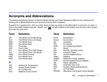
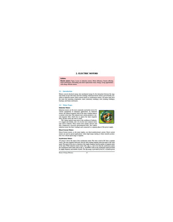
2. ELECTRIC MOTORSSyllabusElectric motors: Types, Losses in induction motors, Motor efficiency, Factors affectingmotor performance, Rewinding and motor replacement issues, Energy saving opportunitieswith energy efficient motors.2.1IntroductionMotors convert electrical energy into mechanical energy by the interaction between the magnetic fields set up in the stator and rotor windings. Industrial electric motors can be broadly classified as induction motors, direct current motors or synchronous motors. All motor types havethe same four operating components: stator (stationary windings), rotor (rotating windings),bearings, and frame (enclosure).2.2Motor TypesInduction MotorsInduction motors are the most commonly used prime mover forvarious equipments in industrial applications. In inductionmotors, the induced magnetic field of the stator winding inducesa current in the rotor. This induced rotor current produces a second magnetic field, which tries to oppose the stator magneticfield, and this causes the rotor to rotate.The 3-phase squirrel cage motor is the workhorse of industry;it is rugged and reliable, and is by far the most common motortype used in industry. These motors drive pumps, blowers andfans, compressors, conveyers and production lines. The 3-phaseinduction motor has three windings each connected to a separate phase of the power supply.Direct-Current MotorsDirect-Current motors, as the name implies, use direct-unidirectional, current. Direct currentmotors are used in special applications- where high torque starting or where smooth acceleration over a broad speed range is required.Synchronous MotorsAC power is fed to the stator of the synchronous motor. The rotor is fed by DC from a separatesource. The rotor magnetic field locks onto the stator rotating magnetic field and rotates at the samespeed. The speed of the rotor is a function of the supply frequency and the number of magnetic polesin the stator. While induction motors rotate with a slip, i.e., rpm is less than the synchronous speed,the synchronous motor rotate with no slip, i.e., the RPM is same as the synchronous speed governedby supply frequency and number of poles. The slip energy is provided by the D.C. excitation powerBureau of Energy Efficiency25
2. Electric Motors2.3Motor CharacteristicsMotor SpeedThe speed of a motor is the number of revolutions in a given time frame, typically revolutionsper minute (RPM). The speed of an AC motor depends on the frequency of the input power andthe number of poles for which the motor is wound. The synchronous speed in RPM is given bythe following equation, where the frequency is in hertz or cycles per second:Synchronous Speed (RPM) 120 FrequencyNo. of PolesIndian motors have synchronous speeds like 3000 / 1500 / 1000 / 750 / 600 / 500 / 375 RPMcorresponding to no. of poles being 2, 4, 6, 8, 10, 12, 16 (always even) and given the mainsfrequency of 50 cycles / sec.The actual speed, with which the motor operates, will be less than the synchronous speed.The difference between synchronous and full load speed is called slip and is measured in percent. It is calculated using this equation:Slip (%) Synchronous Speed – Full Load Rated Speed 100Synchronous SpeedAs per relation stated above, the speed of an AC motor is determined by the number ofmotor poles and by the input frequency. It can also be seen that theoretically speed of an ACmotor can be varied infinitely by changing the frequency. Manufacturer's guidelines should bereferred for practical limits to speed variation. With the addition of a Variable Frequency Drive(VFD), the speed of the motor can be decreased as well as increased.Power FactorThe power factor of the motor is given as:Power Factor Cos φ kWkVAAs the load on the motor comes down, the magnitude of the active current reduces.However, there is no corresponding reduction in the magnetizing current, which is proportional to supply voltage with the result that the motor power factor reduces, with a reduction inapplied load. Induction motors, especially those operating below their rated capacity, are themain reason for low power factor in electric systems.2.4 Motor EfficiencyTwo important attributes relating to efficiency of electricity use by A.C. Induction motors areefficiency (η), defined as the ratio of the mechanical energy delivered at the rotating shaft tothe electrical energy input at its terminals, and power factor (PF). Motors, like other inductiveloads, are characterized by power factors less than one. As a result, the total current draw needed to deliver the same real power is higher than for a load characterized by a higher PF. Animportant effect of operating with a PF less than one is that resistance losses in wiring upstreamof the motor will be higher, since these are proportional to the square of the current. Thus, botha high value for η and a PF close to unity are desired for efficient overall operation in a plant.Squirrel cage motors are normally more efficient than slip-ring motors, and higher-speedmotors are normally more efficient than lower-speed motors. Efficiency is also a function ofBureau of Energy Efficiency26
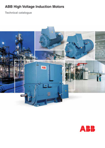
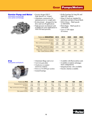
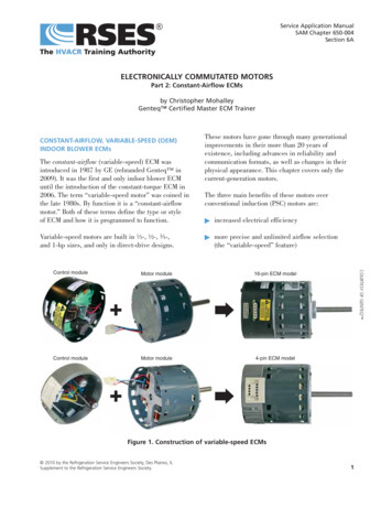
2. Electric Motorsmotor temperature. Totally-enclosed, fan-cooled (TEFC) motors are more efficient than screenprotected, drip-proof (SPDP) motors. Also, as with most equipment, motor efficiency increases with the rated capacity.The efficiency of a motor is determined by intrinsic losses that can be reduced only bychanges in motor design. Intrinsic losses are of two types: fixed losses - independent of motorload, and variable losses - dependent on load.Fixed losses consist of magnetic core losses and friction and windage losses. Magnetic corelosses (sometimes called iron losses) consist of eddy current and hysteresis losses in the stator.They vary with the core material and geometry and with input voltage.Friction and windage losses are caused by friction in the bearings of the motor and aerodynamic losses associated with the ventilation fan and other rotating parts.Variable losses consist of resistance losses in the stator and in the rotor and miscellaneousstray losses. Resistance to current flow in the stator and rotor result in heat generation that isproportional to the resistance of the material and the square of the current (I2R). Stray lossesarise from a variety of sources and are difficult to either measure directly or to calculate, but aregenerally proportional to the square of the rotor current.Part-load performance characteristics of a motor also depend on its design. Both η and PFfall to very low levels at low loads. The Figures 2.1 shows the effect of load on power factorand efficiency. It can be seen that power factor drops sharply at part loads. The Figure 2.2 showsthe effect of speed on power factor.Field Tests for Determining EfficiencyNo Load Test: The motor is run at rated voltage and frequency without any shaft load. Inputpower, current, frequency and voltage are noted. The no load P.F. is quite low and hence lowPF wattmeters are required. From the input power, stator I2R losses under no load are subtracted to give the sum of Friction and Windage (F&W) and core losses. To separate core and F &Figure 2.2 Speed vs. Power factorFigure 2.1 % Load vs. Power factor, EfficiencyBureau of Energy Efficiency27
2. Electric MotorsW losses, test is repeated at variable voltages. It is useful to plot no-load input kW versusVoltage; the intercept is Friction & Windage kW loss component.F&W and core losses No load power (watts) - (No load current)2 Stator resistanceStator and Rotor I2R Losses: The stator winding resistance is directly measured by a bridgeor volt amp method. The resistance must be corrected to the operating temperature. For modern motors, the operating temperature is likely to be in the range of 100 C to 120 C and necessary correction should be made. Correction to 75 C may be inaccurate. The correction factor is given as follows :235 t2R2 , where, t1 ambient temperature, C & t2 operating temperature, C.235 t1R1The rotor resistance can be determined from locked rotor test at reduced frequency, but rotorI R losses are measured from measurement of rotor slip.2Rotor I2R losses Slip (Stator Input – Stator I2R Losses – Core Loss)Accurate measurement of slip is possible by stroboscope or non-contact type tachometer.Slip also must be corrected to operating temperature.Stray Load Losses: These losses are difficult to measure with any accuracy. IEEE Standard112 gives a complicated method, which is rarely used on shop floor. IS and IEC standards takea fixed value as 0.5 % of input. The actual value of stray losses is likely to be more. IEEE –112 specifies values from 0.9 % to 1.8 % (see Table 2.1.)TABLE 2.1 MOTOR RATING VS. STRAYLOSSES - IEEEMotor Rating1 – 125 HPStray Losses1.8 %125 – 500 HP1.5 %501 – 2499 HP1.2 %2500 and above0.9 %Pointers for Users:It must be clear that accurate determination of efficiency is very difficult. The same motor tested by different methods and by same methods by different manufacturers can give a differenceof 2 %. In view of this, for selecting high efficiency motors, the following can be done:a) When purchasing large number of small motors or a large motor, ask for a detailed test certificate. If possible, try to remain present during the tests; This will add cost.b) See that efficiency values are specified without any tolerancec) Check the actual input current and kW, if replacement is doned) For new motors, keep a record of no load input power and currente) Use values of efficiency for comparison and for confirming; rely on measured inputs for allcalculations.Bureau of Energy Efficiency28
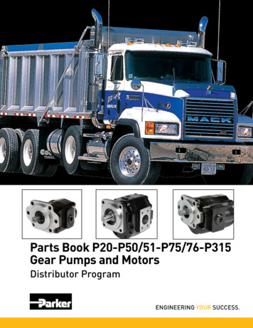
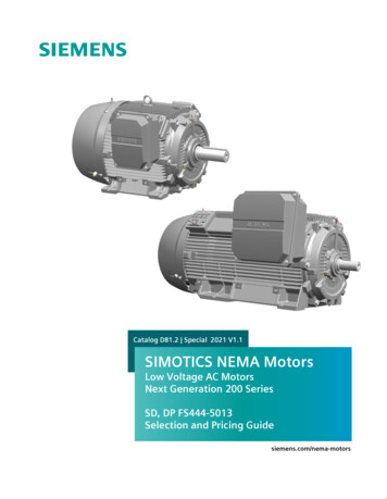
2. Electric MotorsEstimation of efficiency in the field can be done as follows:a) Measure stator resistance and correct to operating temperature. From rated current value ,I2R losses are calculated.b) From rated speed and output, rotor I2R losses are calculatedc) From no load test, core and F & W losses are determined for stray lossThe method is illustrated by the following example:Example :Motor SpecificationsRated powerVoltageCurrentSpeedInsulation classFrameConnection 34 kW/45 HP415 Volt57 Amps1475 rpmFLD 200 LDeltaNo load test DataVoltage, VCurrent, IFrequency, FStator phase resistance at 30 CNo load power, Pnl 415 Volts16.1 Amps50 Hz0.264 Ohms1063.74 WattsBureau of Energy Efficiency29
2. Electric MotorsBureau of Energy Efficiency30
2. Electric Motors2.5 Motor SelectionThe primary technical consideration defining the motor choice for any particular application isthe torque required by the load, especially the relationship between the maximum torque generated by the motor (break-down torque) and the torque requirements for start-up (locked rotortorque) and during acceleration periods.The duty / load cycle determines the thermal loading on the motor. One consideration withtotally enclosed fan cooled (TEFC) motors is that the cooling may be insufficient when themotor is operated at speeds below its rated value.Ambient operating conditions affect motor choice; special motor designs are available forcorrosive or dusty atmospheres, high temperatures, restricted physical space, etc.An estimate of the switching frequency (usually dictated by the process), whether automatic or manually controlled, can help in selecting the appropriate motor for the duty cycle.The demand a motor will place on the balance of the plant electrical system is another consideration - if the load variations are large, for example as a result of frequent starts and stopsof large components like compressors, the resulting large voltage drops could be detrimental toother equipment.Bureau of Energy Efficiency31
2. Electric MotorsReliability is of prime importance - in many cases, however, designers and process engineers seeking reliability will grossly oversize equipment, leading to sub-optimal energy performance. Good knowledge of process parameters and a better understanding of the plant powersystem can aid in reducing oversizing with no loss of reliability.Inventory is another consideration - Many large industries use standard equipment, whichcan be easily serviced or replaced, thereby reducing the stock of spare parts that must be maintained and minimizing shut-down time. This practice affects the choice of motors that mightprovide better energy performance in specific applications. Shorter lead times for securingindividual motors from suppliers would help reduce the need for this practice.Price is another issue - Many users are first-cost sensitive, leading to the purchase of lessexpensive motors that may be more costly on a lifecycle basis because of lower efficiency. Forexample, energy efficient motors or other specially designed motors typically save within a fewyears an amount of money equal to several times the incremental cost for an energy efficientmotor, over a standard-efficiency motor. Few of salient selection issues are given below: In the selection process, the power drawn at 75 % of loading can be a meaningful indicatorof energy efficiency.Reactive power drawn (kVAR) by the motor.Indian Standard 325 for standard motors allows 15 % tolerance on efficiency for motorsupto 50 kW rating and 10 % for motors over 50 kW rating.The Indian Standard IS 8789 addresses technical performance of Standard Motors while IS12615 addresses the efficiency criteria of High Efficiency Motors. Both follow IEC 34-2test methodology wherein, stray losses are assumed as 0.5 % of input power. By the IECtest method, the losses are understated and if one goes by IEEE test methodology, the motorefficiency values would be further lowered.It would be prudent for buyers to procure motors based on test certificates rather thanlabeled values.The energy savings by motor replacement can be worked out by the simple relation : kWsavings kW output [ 1/ηold – 1/ ηnew ] where ηold and ηnew are the existing and proposedmotor efficiency values.The cos
sified as induction motors, direct current motors or synchronous motors. All motor types have the same four operating components: stator (stationary windings), rotor (rotating windings), bearings, and frame (enclosure). 2.2 Motor Types Induction Motors Induction motors are File Size: 714KBPage Count: 20