Transcription
Design and Prototyping Methods for Brushless Motorsand Motor ControlbyShane W. ColtonB.S., Mechanical Engineering (2008)Massachusetts Institute of TechnologySubmitted to the Department of Mechanical Engineeringin Partial Fulfillment of the Requirements for the Degree ofMaster of Science in Mechanical Engineeringat theMassachusetts Institute of TechnologyJune 2010 Massachusetts Institute of TechnologyAll rights reservedSignature of Author . . . . . . . . . . . . . . . . . . . . . . . . . . . . . . . . . . . . . . . . . . . . . . . . . . . . . . . . . . . . .Department of Mechanical EngineeringMay 7, 2010Certified by . . . . . . . . . . . . . . . . . . . . . . . . . . . . . . . . . . . . . . . . . . . . . . . . . . . . . . . . . . . . . . . . . . . .Daniel FreyAssociate Professor of Mechanical Engineering and Engineering SystemsThesis SupervisorAccepted by . . . . . . . . . . . . . . . . . . . . . . . . . . . . . . . . . . . . . . . . . . . . . . . . . . . . . . . . . . . . . . . . . . .David E. HardtRalph E. & Eloise F. Cross Professor of Mechanical EngineeringChairman, Department Committee on Graduate Students1
2
Design and Prototyping Methods for Brushless Motorsand Motor ControlbyShane W. ColtonSubmitted to the Department of Mechanical Engineeringon May 7, 2010 in partial fulfillment of therequirements for the Degree of Master of Science inMechanical EngineeringABSTRACTIn this report, simple, low-cost design and prototyping methods for custom brushless permanentmagnet synchronous motors are explored. Three case-study motors are used to develop, illustrateand validate the methods. Two 500W hub motors are implemented in a direct-drive electricscooter. The third case study, a 10kW axial flux motor, is used to demonstrate the flexibility ofthe design methods. A variety of ways to predict the motor constant, which relates torque tocurrent and speed to voltage, are presented. The predictions range from first-order DC estimatesto full dynamic simulations, yielding increasingly accurate results. Ways to predict windingresistance, as well as other sources of loss in motors, are discussed in the context of the motor’soverall power rating. Rapid prototyping methods for brushless motors prove to be useful in thefabrication of the case study motors. Simple no-load evaluation techniques confirm the predictedmotor constants without large, expensive test equipment.Methods for brushless motor controller design and prototyping are also presented. The casestudy, a two channel, 1kW per channel brushless motor controller, is fully developed and used toillustrate these methods. The electrical requirements of the controller (voltage, current,frequency) influence the selection of components, such as power transistors and bus capacitors.Mechanical requirements, such as overall dimensions, heat transfer, and vibration tolerance, alsoplay a large role in the design. With full-system prototyping in mind, the controller integrateswireless data acquisition for debugging. Field-oriented AC control is implemented on low-costhardware using a novel modification of the standard synchronous current regulator. Thecontroller performance is evaluated under load on two case study systems: On the direct-driveelectric scooter, it simultaneously and independently controls the two motors. On a highperformance remote-control car, a more extreme operating point is tested with one motor.Thesis Supervisor: Daniel FreyTitle: Associate Professor of Mechanical Engineering and Engineering Systems3
Table of Contents1Introduction. 61.1Project Motivation . 61.2Acknowledgments. 72Fundamentals and Relevant Physical Principles. 82.1Brushless Motor Terminology and Types. 82.1.1Basic Terminology. 82.1.2Motor Model, Back EMF, Motor Constant . 102.1.3Resistance, Inductance, Saliency, and Field Weakening. 122.2DC vs. AC: Back EMF, Drive, and Torque Production . 132.2.1Trapezoidal vs. Sinusoidal Back EMF. 142.2.2Square Wave vs. Sine Wave Drive . 152.2.3Torque Production Comparison. 172.2.4Mixed Back EMF / Drive . 192.2.5DC vs. AC Summary . 212.3Field-Oriented Control. 222.3.1d-q Reference Frame. 222.3.2Vector Motor Quantities . 232.3.3Why Control is Necessary: Motor Inductance. 262.3.4Field-Oriented Control Objective . 282.3.5Synchronous Current Regulator. 293Brushless Motor Design and Prototyping Methods . 313.1Design Strategy and Goals. 313.2Introduction of Case Studies. 323.2.1Direct-Drive Kick Scooter Motors. 323.2.2Axial Flux Motor . 343.3Motor Constant: Various Prediction Methods . 413.3.1First-Order Analysis: DC. 413.3.2First-Order Analysis: Sinusoidal. 463.3.32D Finite Element: Static. 483.3.42D Finite Element: Dynamic . 523.4Resistance, Losses, and Power Rating. 553.4.1I² Losses: Winding Resistance, Power Ratings . 563.4.2E² Losses: Delta Windings, Eddy Current, and Mechanical Losses. 593.5Motor Prototyping Methods. 623.5.1Integrated CAD/FEA/CAM . 623.5.2Design for Assembly (and Disassembly). 653.6Evaluating Motor Performance. 673.6.1Single-Phase Back EMF Testing . 683.6.2Full-Motor Testing. 694Motor Control Design and Prototyping Methods . 714.1Design Strategy and Goals. 714.2Introduction of Case Study . 724.3Controller Design. 734.3.1MOSFETs . 734.3.2Bus Capacitors . 824
4.3.3Power Supplies. 854.3.4Signal Filtering. 874.4Controller Layout and Mechanical Design . 874.4.1Power/Signal Isolation . 874.4.2Mechanical Constraints and Design. 884.5Field-Oriented Control Strategy . 934.5.1Control Overview. 934.5.2Hall Effect Sensor Interpolation for Rotor Position . 934.5.3Modified Synchronous Current Regulator. 964.6Data Acquisition and Analysis. 994.6.1Integrated Wireless Data Acquisition . 994.6.2Data Visualization/Analysis: Real Time and Post-Processed. 1004.7Evaluating Controller Performance . 1014.7.1Direct-Drive Scooter Motors . 1014.7.2RC Car Motor . 1055Conclusions. 1086References. 1097Appendices. 1107.1Modular, Optically-Isolated Half-Bridge. 1107.1.1MOSFETs . 1117.1.2Optocouplers . 1137.1.3Drive Signal Inverter. 1147.1.4DC/DC Converter (High-Side Supply). 1147.1.5Full Half-Bridge. 1157.1.6Controlling the Half-Bridge. 1187.2Schematic of Case Study Controller . 1207.3Source Code of Case Study Controller . 1257.3.1lookups.h. 1257.3.2main.c. 1255
1 Introduction1.1 Project MotivationElectric motors are one of the key elements of mechanical design, used in many applicationsranging from toys to propulsion of full-scale vehicles. Few if any simpler ways exist to producetorque and rotary motion; most electric motors have a single moving part. Thanks in large part tothis simplicity, electric motors also have a high-fidelity electromechanical model. This modelcan be used to accurately predict motor and full-system performance. A thorough understandingof this model is useful whether selecting a motor from a catalog or designing one from scratch.Brushless permanent magnet synchronous motors (PMSM) are increasingly replacing brushedDC motors in low- to medium-power servo applications. In these motors, electroniccommutation is used in lieu of mechanical brushes. This reduces friction, increases reliability,and decreases the cost to produce the motor itself. The tradeoff is more complex and expensivecontrollers. However, the economies of scale of electrical components are very different thanthose of the motors themselves, and a system-wide cost/performance evaluation favors brushlessmotors in many applications.For the author, brushless motors present an interesting educational opportunity as well.Specifically, they can be designed, built, and tested without the need for special tools thanks totheir simplicity. Using the motor model, a first-order analysis can predict the motor’sperformance to good accuracy. Free simulation tools for electromagnetic finite element analysis[1] can yield even better predictions. Without a brush and commutator assembly, the onlymechanical element that cannot be made with standard machining capability is the laminatedstator core. Rapid prototyping, in the form of laser cutting, can produce this part with no toolingcost. In other cases, existing stator cores can be bought or salvaged if they fit the design. Handwinding and magnet placement is possible and effective for smaller motors.The opportunity to explore brushless motors first presented itself in the form of a project carriedout during the summer of 2009. As part of the Edgerton Center’s Summer EngineeringWorkshop [2,3], the author led a team of students to produce a direct-drive kick scooter usingcustom brushless hub motors. These motors are introduced as case studies in Section 3.2.1. Athorough understanding of the motor model was developed throughout this project. At the sametime, many of the practical issues in implementing a real motor design came up. The opportunityfor a significant design study was apparent. A second case-study motor, originally designed foran electric motorcycle, was developed as part of this design study. This motor, a larger axial-fluxconfiguration, has a very different topology but can be analyzed in much the same way,demonstrating the flexibility of the design methods.After completing the motor design and fabrication for the direct-drive scooter with the SummerEngineering Workshop, the author pursued a more advanced control method. Like manyinexpensive brushless motors, the scooter hub motors used Hall effect sensors and square-wavecommutation, typically referred to as brushless DC since it mimics the function of a brush andcommutator. Using sinusoidal AC control, even on motors designed for brushless DC, offers6
advantages such as quieter/smoother operation and higher controller efficiency. Mechanicalconsiderations such as poor thermal management and vibration tolerance also made the originalbrushless DC scooter controller less than ideal. The controller presented in Section 4 wasoriginally designed to solve specific problems with the first scooter controller. However, it alsodemonstrates the extension of full sinusoidal AC motor control to low-cost hardware. It uses theexisting Hall effect sensors and interpolation in lieu of more expensive position feedbackdevices. It is also optimized to run on low-speed fixed-point microprocessors.All of the motor and controller design and testing and most of the fabrication for this study weredone in-house using only standard, commonly-available tools and equipment. This is effectiveproof that it is possible to do in-house motor and controller design even in labs for which that isnot the primary focus. This obviously has its limits: building a full-scale vehicle motor orcontroller is likely beyond the capability of most individuals or labs. But for low- to mediumpower applications, it is possible to design and develop custom motor and motor controlsolutions in-house. The methods presented in this report put emphasis on low cost and shortdesign cycle time; rapid prototyping for motors. Admittedly, specialized research anddevelopment in electric machines goes much further than what is presented in this report. Thegoal here will be to illustrate a simple motor and controller design and prototyping process thatcould fit into a higher-level system design.1.2 AcknowledgmentsThe author would like to thank Professor Daniel Frey for supervising this project. Very fewadvisors would be willing to give as much freedom and trust to explore a design as Dan does,and this project would not have been possible without his support.The author would also like to thank the Edgerton Center and the Summer Engineering Workshopcrew for continuing to provide a source of interesting projects and a fun place to work. Theopportunity to combine technical study with educational and teaching opportunity is somethingthat is unique and much appreciated.The author would like to thank Charles Guan ’11 for providing inspiration and technical supportfor the projects, particularly the direct drive electric scooter.The author would like to thank the MIT Electric Vehicle Team for providing opportunities to dointeresting research on traction motors. In particular, thanks to Lennon Rodgers for his support ofthe axial flux motor project, as well as for his general technical knowledge and guidance.The author would like to thank Proto Laminations, Inc, for providing laser-cut laminations at nocost for the scooter motors, as well as the Electric Motor Education and Research Foundation forsupporting an enlightening trip to the SMMA Fall Technical Conference. In particular, the authorwould like to thank Steve Sprague for his personal involvement in the project and commitmentto electric motor education and research.7
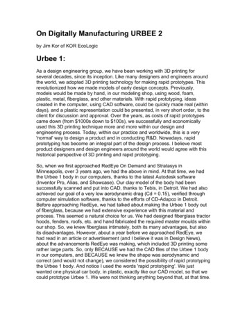
2 Fundamentals and Relevant Physical PrinciplesThis section will first cover some brushless motor terminology and taxonomy, and then outlinesome fundamental physical principles that will be relevant to the rest of the report. A fullcoverage of electric machine theory is beyond the scope of this report. See [4] for morebackground on electric machine theory and [5] for more background on motor control.2.1 Brushless Motor Terminology and TypesIn more precise terminology, this report focuses on permanent magnet synchronous motors(PMSM). These are motors in which permanent magnets on the rotor create a magnetic fieldwhich interact with synchronous stator current. “Synchronous” simply means that the electricaland mechanical frequencies are linked. There is no “slip” as there would be in an AC inductionmotor.For brevity, the term “brushless motor” is used in this report to mean “permanent magnetsynchronous motor.” AC induction motors, and other motors that technically don’t have brushes,are not included in this classification. However, the term is not restricted to brushless DC(BLDC). Thus, it also includes other common motor classifications such as permanent magnetAC (PMAC) and brushless AC (BLAC). The technical difference between DC and ACpermanent magnet synchronous motors is a common point of confusion, addressed in Section2.2.2.1.1 Basic TerminologyBrushless motors consist of a stationary part, the stator, and a rotating part, the rotor. The spacebetween the stator and the rotor is called the air gap. The stator carries the windings and therotor carries the magnets. Brushless motors can have inside rotors or outside rotors. These twocases are shown in Figure 1. In either case, the stator and windings are stationary, allowing directwinding access without brushes or slip rings.Figure 1: The rotor can be on the inside (left) or the outside (right). In either case, the stator, which containswindings, does not rotate and the rotor, which contains magnets, does.8
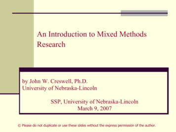
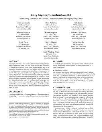
In most brushless motors, windings are placed in slots in a laminated steel structure called thecore. The purpose of the steel is to channel more magnetic flux through the winding than wouldbe possible with a non-ferrous core. The section of steel between two slots is called a tooth.Three-phase motors have a number of slots (and teeth) that is evenly divisible by three. Figure 2shows a 12-slot stator for an outside rotor brushless motor, with a slot and tooth labeled.Figure 2: A 12-slot stator for an outside rotor brushless motor. Windings are placed in slots, wrapped around teeth.A phase is an individual group of windings with a single terminal accessible from outside themotor. Most brushless motors are three-phase. Each individual loop of wire making up a phasewinding is called a turn. A pole is a single permanent magnet pole, north or south. Theminimum number of poles is two, but motors can have any even number of poles. Larger motorstend to have more poles. The number of poles is not directly related to the number of slots,although there are common combinations of slot and pole counts that work well [6].In motors with more than two poles, it is important to define the difference between mechanicalangles and electrical angles. Mechanical angle is the physical angle as would be measured with aprotractor. Electrical angle represents a relative position within one magnetic period, whichspans two poles. This difference is illustrated in the case of a 4-pole motor in Figure 3.9
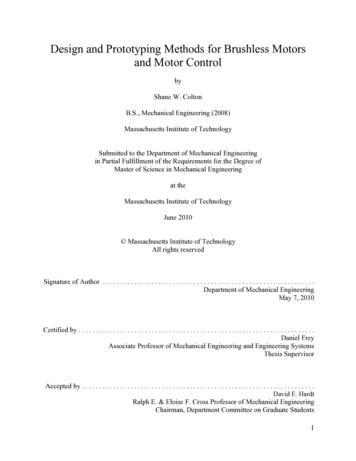
Figure 3: The difference between mechanical angle and electrical angle, illustrated on a 4-pole motor.Electrical and mechanical angle and angular velocity are related by e Mod p m ,360º 0 e p mwhere p is the number of pole pairs. (For 2-pole motors, the angles and frequencies areequivalent.) For angular velocity, the conversion is straightforward. For angular position, theconversion is modulo 360º and has some offset, θ0.2.1.2 Motor Model, Back EMF, Motor ConstantPermanent magnet motors are well-modeled as a speed-dependent voltage source in series withan inductor and a resistor. The speed-dependent voltage source is called the back EMF, and is aphysical consequence of wire loops moving through a varying magnetic field. In the case of abrushed DC motor, the back EMF is a constant DC voltage proportional to speed. The constantof proportionality is called the motor constant, often designated Kt, Kv, or Km. In this report, Ktwill be used. The electromechanical model for a brushed DC motor is shown in Figure 4.Figure 4: The electromechanical model for a brushed DC motor contains an ideal transformer in series with aresistor and an inductor.10
The motor constant, Kt, sets both the torque per unit current and the back EMF voltage per unitspeed. Both of these ratios have the same SI base units and the equivalency of these twoconstants is a consequence of power conservation in the ideal transformer part of the model. (Alllosses are accounted for by external elements such as the resistance.)This model can be modified for brushless motors (DC or AC). In a brushed motor, the positionsof current-carrying windings with respect to the magnets are fixed by the brushes. In a brushlessmotor, this is a variable. One way to capture this is to allow the motor constant, Kt, to become aperiodic function of electrical angle. The model can then be applied independently to each of thethree phases, as shown in Figure 5. This model assumes balanced phases with the same numberof turns per phase, the same phase resistance, and the same inductance. The angular velocity isleft defined as mechanical speed, ωm, to simplify the analysis.Figure 5: The DC motor model extended to a three-phase brushless motor.This extension of the simple model to three-phase brushless might seem cumbersome, but in factit is very powerful in this most general form. So far, nothing at all has been assumed about theshape of Kt(θe), other than that it is periodic in electrical angle. Nothing has been assumed aboutthe driving currents either, other than that they sum to zero. Applying this general model todifferent motor/drive combinations reveals the many complexities of brushless motors, first andforemost the difference between brushless DC and AC, which will be discussed in Section 2.2.However, the fundamental unit of analysis is still simple.11
One way to see the exact shape of Kt(θe) is to spin the motor with no load and measure theperiodic back EMF waveform. (Analogous to spinning a brushed DC motor and measuring theDC voltage it produces to determine Kt.) The back EMF per unit mechanical speed is Kt(θe), andthis is also the function that defines torque per unit current. The goal of brushless motor controlis to drive each phase with the appropriate current to get net torque at that angle. Thus, someform of angular position measurement is necessary for commutation.The factors that contribute to Kt(θe), as well as methods for estimating its magnitude and shape,will be discussed in Section 3.3.2.1.3 Resistance, Inductance, Saliency, and Field WeakeningMotor windings, since they consist of coils of copper wire, have an electrical resistance. Thoughthe resistance is distributed along the length of the coil, it can be modeled as a simple seriesresistor on each phase as in Figure 5. The winding resistance per phase, Ra from here onward, iseasy to measure and to predict based on the resistivity of copper. Since power is dissipated in thisresistor, it contributes strongly to motor inefficiency. In fact, it is the only source of loss that iscaptured by the simple model. At many operating points, resistive loss is the dominant loss in amotor and the simple model is sufficient for predicting motor efficiency. One importantexception is at or near no-load speed, where currents are small and speed-dependent losses (e.g.friction, eddy current) become dominant.The total power dissipated by the motor resistance depends on the shape of the drive currents.Most generally, it is calculated by:Pr 32 I ( ) 2 202Ra d 3I rmsRa .The root mean square current captures the effect of waveform shape. This comes in handy whenexploring the differences between square wave and sine wave drive currents, which will bediscussed in Section 2.2.2.Motor windings also have inductance. Physically, this means that current flowing in thewindings will induce magnetic flux through them, even in the absence of permanent magnet flux.It also means that the windings will resist rapid changes in current by generating voltage acrossthis inductor. However, this is not the back EMF. Back EMF is only the component of voltagethat is generated by the permanent magnet flux. Thus, there is a separate series inductor in themotor model.The value of inductance is less straightforward to calculate because the phases are notmagnetically independent. That is, current in one phase can induce flux in another. Undersinusoidal drive currents, it is possible to use a lumped inductance, called the synchronousinductance, to accommodate for this. The value of the synchronous inductance is:Ls 3La ,212
where La is the inductance that would be measured independently on one phase, if it could beisolated. This is derived in [4]. For the purposes of this report, some lumped inductance perphase, Ls, will be assumed even for non-sinusoidal drive currents.The winding inductance has many theoretical and practical effects on the motor. It stores energyin the form of a magnetic field any time there is current in the winding. When a winding isswitched off, this energy must go somewhere. For this reason, controllers contain “flybackdiodes” that allow this current to circulate even when all the switches are open. Under highfrequency pulse-width modulated (PWM) control, the winding inductance also filters out currentripple. However, as a low-pass filter on current it also creates phase lag. This lag is explored indetail in Section 2.3.3 as motivation for the use of field-oriented control.The winding inductance is a function of motor geometry and the number of turns in the winding.In non-salient motors, also called round rotor, the inductance is not a function of electricalangle. This is the case for motors with complete radial symmetry of the rotor’s steel backing atany angle. (The magnets themselves don’t matter, since they have nearly the same permeabilityas air.) Motors with magnets mounted to the surface of the rotor steel, called surface permanentmanget (SPM), fall into this category. Salient motors have an inductance that varies periodicallywith electrical angle. This is the case if the rotor’s steel backing is different at the poles than inbetween them. Motors with magnets embedded in the steel backing, called interior permanentmagnet (IPM), fall into this category. This report will focus exclusively on non-salient, SPMmotors. Torque production for salient motors requires a slightly more complicated analysis.Motor inductance also has a large effect on field weakening, a technique usually used to extendthe operating speed range of a motor. In field weakening, some current is used to induce a fieldwhich partially cancels the permanent magnet field. This results in less torque per unit current,but also decreases the back EMF per unit speed, allowing the motor to be operated to higherspeeds with a
In this report, simple, low-cost design and prototyping methods for custom brushless permanent magnet synchronous motors are explored. Three case-study motors are used to develop, illustrate and validate the methods. Two 500W hub motors are implemented in a direct-drive electric . 3 Br