Transcription
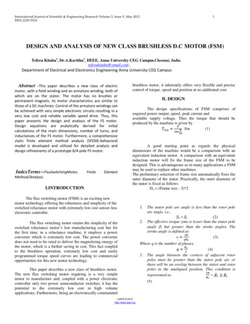
International Journal of Scientific & Engineering Research Volume 3, Issue 5, May-2012ISSN 2229-55181DESIGN AND ANALYSIS OF NEW CLASS BRUSHLESS D.C MOTOR (FSM)Tefera Kitaba1, Dr.A.Kavitha2, DEEE, Anna University CEG Campus Chennai, India.teferakitaba@ymail.com ,Department of Electrical and Electronics Engineering Anna University CEG CampusAbstract -This paper describes a new class of electricmotor, with a field winding and an armature winding, both ofwhich are on the stator. The motor has no brushes orpermanent magnets. Its motor characteristics are similar tothose of a DC machines. Control of the armature windings canbe achieved with very simple electronic circuits resulting in avery low cost and reliable variable speed drive. Thus, thispaper presents the design and analysis of the FS motor.Design equations are analytically derived for initialcalculations of the main dimensions, number of turns, andinductances of the FS motor. Furthermore, a comprehensivestatic finite element method analysis (SFEM)-behavioralmodel is developed and utilized for detailed analysis anddesign refinements of a prototype 8/4-pole FS sis.FiniteElementI.INTRODUCTIONbrushless motor, it inherently offers very flexible and precisecontrol of torque, speed and position at no additional cost.II. DESIGNThe design specifications of FSM comprises ofrequired power output, speed, peak current andavailable supply voltage. Thus the torque that should beproduced by the machine is given byNm(1)A good starting point as regards the physicaldimensions of the machine would be a comparison with anequivalent induction motor. A comparison with an equivalentinduction motor will fix the frame size of the FSM to bedesigned. This is advantageous as in many applications a FSMmay be used to replace other machines.The preliminary selection of frame size automatically fixes theouter diameter of the stator. Practically, the outer diameter ofthe stator is fixed as followsDo (Frame size - 3)*2The flux switching motor (FSM) is an exciting newmotor technology offering the robustness and simplicity of theswitched reluctance motor with extremely low cost sensor-lesselectronic controller.The flux switching motor retains the simplicity of theswitched reluctance motor‟s low manufacturing cost but forthe first time, in a reluctance machine, it employs a powerconverter which is extremely low cost. The power converterdoes not need to be rated to deliver the magnetizing energy ofthe motor, which is a further saving in cost. This fact coupledto the brushless operation, extremely low cost and easilyprogrammed torque speed curves are leading to commercialopportunities for this new motor technology.This paper describes a new class of brushless motor.The new flux switching motor requiring is a very simplemotor to manufacture and, coupled with a power electroniccontroller only two power semiconductor switches; it has thepotential to the extremely low cost in high volumeapplications. Furthermore, being an electronically commutatedIJSER 2012http://www.ijser.org1.2.The stator pole arc angle is less than the rotor polearc angle, i.e.,(2)s rThe effective torque zone is lesser than the stator poleangle s but greater than the stroke angle . Thestroke angle is defined as(3)Where q is the number of phases,3.(4)The angle between the corners of adjacent rotorpoles must be greater than the stator pole arc orthere will be an overlap between the stator and rotorpoles in the unaligned position. This condition isrepresented as(5)
International Journal of Scientific & Engineering Research Volume 3, Issue 5, May-2012ISSN 2229-5518Fig 2. Structure of the FSMWith the assumptions of flux density in both stator and rotorother machine parameters are found. Figure 3 shows themagnetic equivalent ciruit.1The first IGBT is switched on and current from thesupply flows through the corresponding armaturewinding. The rotor turns to align itself with theenergized stator poles as a consequence of the resultantcombined flux produced by both the armature and fieldwindings. As rotation continues the position sensordetects the point at which to turn on the second IGBT.The first switch must be turned off prior to, or at thesame time as the second turns on to avoid a large shortcircuit current. At first the stored magnetic energytransfers to the second armature winding. As this iswound in the opposite direction to the first armaturewinding, the current now flowing in this winding isnegative and reduces to zero as energy is returned to thesupply via the fast recovery freewheel diode.Fig 4 switch power converterThe current in the second half of the armaturewinding now reverses to provide the reverse MMFallowing the motor to continue to rotate. Incompletecoupling between the two armature windings requiresFig 3. Per phase equivalent circuitthat the leakage energy be dissipated in a R-C snubberthat is referenced to the positive supply rail. ThisThe specification of the machine designed are, power 2.6Hp,speed 1500 rpm, supply voltage 230V, rated current 12A,number of turns per phase 70.commutation process continues in synchronism withrotation.III. PERFORMANCE OF THE MOTORB. SIMULATION RESULT OF ARMATUR CURRENT1086Armature time0.9830.9840.9850.986VI. FINITE ELEMENT RESULTSV. POWER CONVERTERThe model developed in Magnet solver 7.13 is shown in figure5. The default meshes and the meshes after the placement ofnodes at air gap and pole tip for refinement is also comparedas the following figures.IJSER 2012http://www.ijser.org
International Journal of Scientific & Engineering Research Volume 3, Issue 5, May-2012ISSN 2229-55181A.STATIC 2D SIMULATION RESULTSFig.7c Arrow plot of flux densityFig 5. Meshes refinementFig.7d Mutual inductance at 67.5 degree rotor positionFigure 7a Flux Paths in AlignedFig. 7e Self inductace of phase „A‟ and‟F‟ for 90 degreerotor postionFigure 7b Flux Paths Unaligned PositionsFig.7fMutual inductance as position of rotor varyingIJSER 2012http://www.ijser.org
International Journal of Scientific & Engineering Research Volume 3, Issue 5, May-2012ISSN 2229-5518Fig.7gMagnitude of flux intesity in air gap vs distance acrossthe machine diameter1B.DYNAMICRESULTS2DSIMULATIONFig.7hFlux linkage vs. current plot for self inductanceFig.8a No load speed curve forforward motoringFig.i Flux linkage vs. current plot for mutualinductanceVII.RESULTSN.SNotationsEnergy stored andtorque1W10.545J2W21.9983J3W2.5433J412.953NmFig 8b Torque vs time and fluxTable 1Average torque and work donecharacteristics of the machineApproximatelyIJSER 2012http://www.ijser.org
International Journal of Scientific & Engineering Research Volume 3, Issue 5, May-2012ISSN 2229-55181VII. �DesignofElectrical Machines”NaiSarak, Delhi, 20092. IEEE Transaction on “New class magnet andFig .8cPosition of the rotor vs time characteristics(forwardmotoring)brushless d.c motors” (2008-10)3. Krishnan, R., “Switched Reluctance Motor Drivesmodeling, simulation”CRC Press New York, 20014. T.J.E .Miller “Brushless permanent magnet andreluctance motor drives” Clarendon press, 19995. Nicola Bianchi “Electrical machine analysis usingfinite Element”Clarendon press, enShahdra, Delhi, 1998VIII. BIO GRAPHIESFig.8e No load speed curve forreverse motoringTefera Kitaba is a Post Graduate Student in the Departmentof Electrical andElectronics Engineering, College ofEngineering, Guindy, AnnaUniversity, Chennai.Dr.A.Kavitha,assintantProfesor received her B.E. degreefrom Kamaraji University, and M.E degree and Ph.d fromIIT, Madras University and CEG, Anna Universityrespectively. She is a member of ISTE. She is presentlyworking as an assistant professor in the department ofelectrical engineering in Anna University.Fig .8f Position of the rotor vs timecharacteristics(revese motoring)VIII. CONCLUSIONThe paper identifies the features of the powerful simulationsoftware MAGNET 7.13 for the analysis of the field. Analysisof various parameters like coenergy, flux linkages and torque plot reveals that differenttypes of configurations of FSM can be modeled, and analyzedfor improving the performance. The simulated solutions haveshown that the model is advantageous however in practicalsituations various other parameters have to be taken intoconsiderations.IJSER 2012http://www.ijser.org
2. IEEE Transaction on “New class magnet and brushless d.c motors” (2008-10) 3. Krishnan, R., “Switched Reluctance Motor Drives modeling, simulation” CRC Press New York, 2001 4. T.J.E .Miller “Brushless permanent magnet and reluctance motor drives” Clarendon press,