Transcription
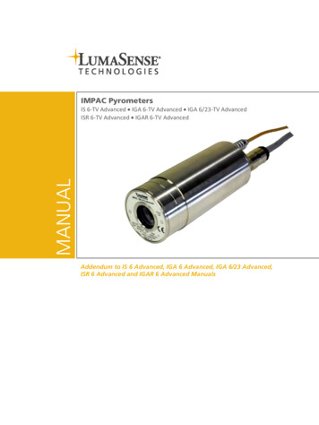
IMPAC PyrometersMANUALIS 6-TV Advanced IGA 6-TV Advanced IGA 6/23-TV AdvancedISR 6-TV Advanced IGAR 6-TV AdvancedAddendum to IS 6 Advanced, IGA 6 Advanced, IGA 6/23 Advanced,ISR 6 Advanced and IGAR 6 Advanced Manuals
Confidential InformationThe material contained herein consists of information that is the property of LumaSenseTechnologies and intended solely for use by the purchaser of the equipment described in thismanual. All specifications are subject to change without notice. Changes are made periodicallyto the information in this publication, and these changes will be incorporated in new editions.LumaSense Technologies prohibits the duplication of any portion of this manual or the usethereof for any purpose other than the operation or maintenance of the equipment describedin this manual, without the express written permission of LumaSense Technologies.Copyright LumaSense Technologies 2016. All rights reserved.TrademarksIMPAC is a trademark of LumaSense Technologies.All other trademarks are trademarks, registered trademarks, and/or service marks of theirrespective holders.Service CentersLumaSense Technologies, Inc.North AmericaSales & ServiceSanta Clara, CA, USAPh: 1 800 631 0176Ph: 1 408 727 1600Fax: 1 408 727 1677LumaSense Technologies GmbHOther Than North AmericaSales & Support60326 Frankfurt, GermanyPh: 49 (0) 69 97373 0Fax: 49 (0) 69 97373 167Global and Regional CentersOur HeadquartersLumaSense Technologies, Inc.Santa Clara, CA, USAPh: 1 800 631 0176Fax: 1 408 727 1677Americas, Australia, & Other AsiaLumaSense Technologies, Inc.Santa Clara, CA, USAPh: 1 800 631 0176Fax: 1 408 727 1677Europe, Middle East, AfricaLumaSense Technologies GmbH60326 Frankfurt, GermanyPh: 49 (0) 69 97373 0Fax: 49 (0) 69 97373 167BrazilLumaSense, Vendas BrasilCampinas, BrasilPh: 55 19 3367 6533Fax: 55 19 3367 6533IndiaLumaSense Technologies, IndiaMumbai, IndiaPh: 91 22 67419203Fax: 91 22 67419201ChinaLumaSense Technologies, ChinaShanghai, ChinaPh: 86 133 1182 7766Ph: 86 21 5877 umasenseinc.comPart No 03 904 212 - ENRevision ENovember 2016
Contents1General Information. 51.1 Information about the user manual. 51.1.1 Legend . 51.1.2 Terminology . 51.2 Safety . 51.3 Limit of liability and warranty . 51.4 Unpacking the Instrument . 61.5 Transport, Packing, Storage . 61.6 Service Request, Repair, or Support . 61.7 Shipments to LumaSense for Repair . 71.8 Disposal / decommissioning . 72Introduction . 92.1 Technical Data . 92.2 Dimensions . 103Electrical Installation. 113.1 Video Output Electrical Connection . 113.1.1 Video Image . 11Operating Mode. 124Software InfraWin . 134.1 Set Video Mode Parameters . 134.2 Adjusting Brightness . 135Accessory (optional) . 175.1 Video Grabber (Converts Analog TV to USB) . 175.1.1 Adjusting Grabber Settings . 175.1.2 Adjusting Video Output Settings . 185.1.3 Viewing the Video Image. 186Data format Universal Pyrometer Protocol (UPP): Extended for Video Module . 197Reference Numbers . 237.1 Reference numbers instrument . 237.2 Reference numbers accessories (video related) . 237.3 Reference numbers accessories (other) . 24Index . 25Series 6 – TV Advanced ManualContents iii
To ensure consistent document formatting, this page was intentionally left blank.Series 6 – TV Advanced ManualContents iv
1 General Information1.1Information about the user manualCongratulations on choosing the high quality and highly efficient IMPAC Series 6-TV Advancedpyrometer.This manual provides important information about the instrument and can be used as a work ofreference for installing, operating, and maintaining your Series 6-TV Advanced pyrometer. It isimportant that you carefully read the information contained in this manual and follow all safetyprocedures before you install or operate the instrument.To avoid handling errors, keep this manual in a location where it will be readily accessible.Note: This user manual is intended to supplement the Series 6 Advanced pyrometermanual for the TV version. Additional information about the pyrometer can be foundin the corresponding IS 6 Advanced, IGA 6 Advanced, IGA 6/23 Advanced,ISR 6 Advanced, or IGAR 6 Advanced manual.1.1.1 LegendNote: The note symbol indicates tips and useful information in this manual. All notesshould be read to effectively operate the instrument.Attention: This sign indicates special information which is necessary for a correcttemperature measurement.Warnings and Cautions: The general warnings and cautions symbol signifies thepotential for bodily harm or damage to equipment.MBShortcut for Temperature range (in German: Messbereich)1.1.2 TerminologyThe terminology used in this manual corresponds to the VDI- / VDE-directives 3511, Part 4.1.2SafetyThis manual provides important information on safely installing and operating theSeries 6-TV Advanced pyrometer. Several sections of this manual provide safety warnings toavert danger. These safety warnings are specified with a warning symbol. You must read andunderstand the contents of this manual before operating the instrument even if you have usedsimilar instruments or have already been trained by the manufacturer.It is also important to continually pay attention to all labels and markings on the instrument andto keep the labels and markings in a permanent readable condition.Warning: The pyrometer is only to be used as described in this manual. It isrecommended that you only use accessories provided by the manufacturer.1.3Limit of liability and warrantyAll general information and notes for handling, maintenance, and cleaning of this instrumentare offered according to the best of our knowledge and experience.Series 6 – TV Advanced ManualGeneral Information 5
LumaSense Technologies is not liable for any damages that arise from the use of any examplesor processes mentioned in this manual or in case the content of this document should beincomplete or incorrect. LumaSense Technologies reserves the right to revise this document andto make changes from time to time in the content hereof without obligation to notify anyperson or persons of such revisions or changes.All instruments from LumaSense Technologies have a regionally effective warranty period.Please check our website at http://info.lumasenseinc.com/warranty for up-to-date warrantyinformation. This warranty covers manufacturing defects and faults which arise duringoperation, only if they are the result of defects caused by LumaSense Technologies.The Windows compatible software was thoroughly tested on a wide range of Windowsoperating systems and in several world languages. Nevertheless, there is always a possibility thata Windows or PC configuration or some other unforeseen condition exists that would cause thesoftware not to run smoothly. The manufacturer assumes no responsibility or liability and willnot guarantee the performance of the software. Liability regarding any direct or indirectdamage caused by this software is excluded.The warranty is VOID if the instrument is disassembled, tampered with, altered, or otherwisedamaged without prior written consent from LumaSense Technologies; or if considered byLumaSense Technologies to be abused or used in abnormal conditions. There are no userserviceable components in the instrument.1.4Unpacking the InstrumentBefore shipment, each instrument is assembled, calibrated, and tested at the LumaSense Factory.When unpacking and inspecting your system components, you need to do the following:1. Check all materials in the container against the enclosed packing list.LumaSense Technologies cannot be responsible for shortages against the packing listunless a claim is immediately filed with the carrier. Final claim and negotiations with thecarrier must be completed by the customer.2. Carefully unpack and inspect all components for visible damage. If you note any damageor suspect damage, immediately contact the carrier and LumaSense Technologies, Inc.3. Save all packing materials, including the carrier’s identification codes, until you haveinspected all components and find that there is no obvious or hidden damage.Note: LumaSense encourages you to register your product with us to receive updates,product information, and special service on.1.5Transport, Packing, StorageWith faulty shipping, the instrument can be damaged or destroyed. To transport or store theinstrument, please use the original box or a box padded with sufficient shock-absorbingmaterial. For storage in humid areas or shipment overseas, the device should be placed inwelded foil (ideally along with silica gel) to protect it from humidity.The pyrometer is designed for a storage temperature of -20 to 80 C with non-condensingconditions. Storing the instrument out of these conditions can cause damage or result inmalfunction of the pyrometer.1.6Service Request, Repair, or SupportContact LumaSense Technologies Technical Support in case of a malfunction or service request.Provide clearly stated details of the problem as well as the instrument model number and serialnumber. Upon receipt of this information, Technical Support will attempt to locate the faultand, if possible, solve the problem over the telephone.Series 6 – TV Advanced ManualGeneral Information 6
If Technical Support concludes that the instrument must be returned to LumaSense Technologiesfor repair, they will issue a Return Material Authorization (RMA) number.Return the instrument upon receipt of the RMA number, transportation prepaid. Clearlyindicate the assigned RMA number on the shipping package exterior. Refer to Section 1.7,Shipments to LumaSense for Repair, for shipping instructions.Technical Support can be contacted by telephone or email:Santa Clara, CaliforniaFrankfurt, GermanyErstein, FranceTelephone: 1 408 727 1600 1 800 631 0176Telephone: 49 (0)69-97373 0Telephone: 33 (0)3 88 98 98 hipments to LumaSense for RepairAll RMA shipments of LumaSense Technologies instruments are to be prepaid and insured byway of United Parcel Service (UPS) or preferred choice. For overseas customers, ship units airfreight, priority one.The instrument must be shipped in the original packing container or its equivalent. LumaSenseTechnologies is not responsible for freight damage to instruments that are improperly packed.Contact us to obtain an RMA number (if one has not already been assigned by TechnicalSupport). Clearly indicate the assigned RMA number on the shipping package exterior.Send RMA Shipments to your nearest technical service center:Santa Clara, CaliforniaFrankfurt, GermanyLumaSense Technologies, Inc.3301 Leonard CourtSanta Clara, CA 95054 USATelephone: 1 408 727 1600 1 800 631 0176LumaSense Technologies GmbHKleyerstr. 9060326 FrankfurtGermanyTelephone: 49 (0)69-97373 0Email: support@lumasenseinc.comEmail: eusupport@lumasenseinc.com1.8Disposal / decommissioningInoperable IMPAC pyrometers must be disposed of in compliance with local regulations forelectro or electronic material.Series 6 - TV Advanced ManualGeneral Information 7
To ensure consistent document formatting, this page was intentionally left blank.Series 6 - TV Advanced ManualGeneral Information 8
2 Introduction2.1Technical Data(Different from IS 6 Advanced, IGA 6 Advanced, IGA 6/23 Advanced, ISR 6 Advanced, orIGAR 6 Advanced)Video-Signal:Date/Time:Connection of Video-Signal:Operating ambienttemperature:FBAS-Signal ca. 1 VSS at 75 Ohms,PAL (B), 50 Hz, CCIR656video output galvanically isolated from power supply, analogoutput and digital interfaceReal time clock with about 14 days buffer (GoldCap)Separate triaxial socket to support double shielded signaltransmission (at pyrometer)BNC connector (on user side - BNC-RCA adapter included)Video signal can be switched off via software0 to 60 C on the housingNote: During operation the instruments will warm up and might reach an intrinsictemperature of up to 58 C.OpticsSuperimposed text elements:Field of view:Resolution:Brightness control:Circular target marker, user text, time, date, measuredtemperatureAdditional: device temperature or distance or serial no. orintensity (only ISR)approx. 11.6% x 8.4% of the adjusted measuring distance768 x 576 Pixel video chip768 x 520 Pixel displayed on screenAutomatic or manual (via software)Note: The calibration / adjustment of this pyrometer is carried out in accordance withVDI/VDE 3511, Part 4.4. See http://info.lumasenseinc.com/calibration for moreinformation.Series 6 – TV Advanced ManualElectrical Installation 9
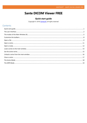
2.2DimensionsAll dimensions in mmSeries 6 – TV Advanced ManualElectrical Installation 10
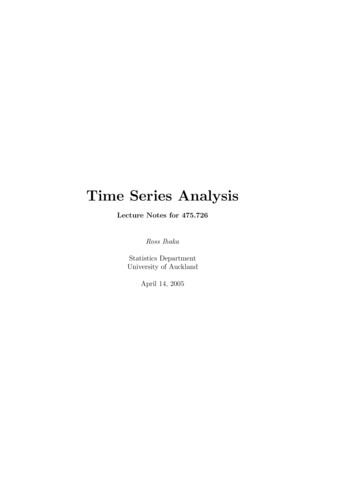
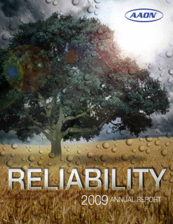
3 Electrical Installation3.1Video Output Electrical ConnectionOn the back cover of Series 6-TV Advanced pyrometers, there is an additional coaxial connectorfor the video output. LumaSense offers ready-made video connection cables in various lengths,which are fitted with a BNC connector and a BNC-RCA adapter to connect to a monitor or videograbber.Triaxial video-outputFocus adjustment set screw4 digit LED display12-pin connectorRear View of the Pyrometer3.1.1 Video ImageThe video image is used for aligning the pyrometer to the measuring object and shows thefollowing information: The measuring object and its surroundingsTarget marking circle (The size of the circle corresponds to the measuring target size)Current temperature readingIn addition to the measuring temperature, one of the following parameters is displayed:o Internal temperature of the pyrometer (Tcase)o Measuring distance (a xxxxx)o Serial number (SNo: xxxx)o Signal intensity (I xxx.x% only ISR 6-TV Advanced and IGAR 6-TV Advanced)Current Time and DateUser text (e.g. "LumaSense")Example of a video imageSeries 6 – TV Advanced ManualElectrical Installation 11
Operating ModeThe two dots above the letter “T” showthe selected operating mode(ISR 6-TV Advanced andIGAR 6-TV Advanced only). 2-channel mode: 2 dotsdisplayed. If the signal fallsbelow the set Relative Signal (see"Relative Signal" inISR 6 Advanced orIGAR 6 Advanced Manual), thetemperature displayed on theimage will be flashing.1-channel mode: only the leftdot is displayed.Metal mode: the left dot is displayed continuously,the right dot flashes.Smart-Mode (IGAR 6-TV Advanced only): both dots flash.Series 6 – TV Advanced ManualElectrical Installation 12
4Software InfraWinYou can configure the video image and display options using a PC and the InfraWin 5 software(included in scope of delivery).4.1Set Video Mode Parameters1. Choose TV for setting the parameters of the video module.2. Complete the following fields on the screen: Text: Enter user text (e.g "LumaSense") Parameters: Display in addition to measuring temperatureo Off (no parameter is displayed)o Device temperatureo Measuring distanceo Serial numbero Signal intensity (ISR 6-TV Advanced and IGAR 6-TV Advanced only) Brightness: Selects the brightness adjustment mode of the video image:automatic or manual Video Output: To turn on/off the video output (high impedance off) Date and Time Settings: Set the current time and date3. Click the Accept button to save the settings.4.2Adjusting BrightnessYou can set the brightness control to Manual (Man.) or Automatic (Auto) using the InfraWin 5software.Series 6 – TV Advanced ManualSoftware Infrawin 13
Manual - the brightness of the video image can be set manually using the slider at theright side of the video image. Automatic - the brightness of the video image is automatically controlled. Using thetwo sliders (red and blue) at the right side of the video image, a range of brightness canbe set where the automatic control should work. With the yellow button, the selectedrange can be moved.If the circle (representing the current brightness) is within the chosen range, automaticbrightness control is not active. Once the circle is outside of the chosen range, automaticbrightness control activates and automattically adjusts the brightness until the circle returns tothe chosen range.These settings affect the video chip in the pyrometer. By pressing the Accept button, thesettings are stored in the pyrometer.Series 6 – TV Advanced ManualSoftware Infrawin 14
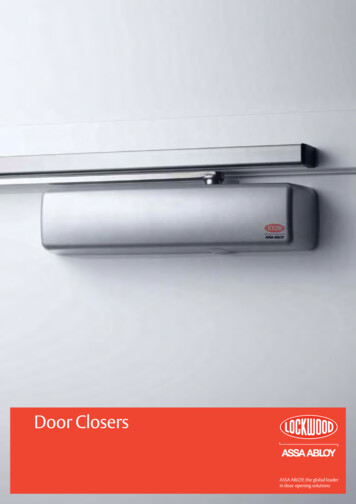
Comparison between manual and automatic control of brightness:The measuring temperature was changed for the image recording from the beginning of themeasuring range to 1200 C.Manual brightness controlSeries 6 – TV Advanced ManualAutomatic brightness controlSoftware Infrawin 15
To ensure consistent document formatting, this page was intentionally left blank.Series 6 – TV Advanced ManualSoftware Infrawin 16
5 Accessory (optional)5.1Video Grabber (Converts Analog TV to USB)Using the video grabber (optional accessory) in conjunctionwith the software InfraWin 5, it is possible to see the videoimage on the PC screen together with the temperature graph.The video image can be size adjusted and positioned at anyplace of the screen. The properties of the pyro's video chip aswell as properties of the video grabber can be adjusted withInfraWin 5.5.1.1 Adjusting Grabber SettingsOn top of the video image there is a menu labeled Grabber settings. Set the properties of thevideo image by changing the parameters of the video grabber (works like the controlling knobsof a monitor).1. Select Grabber settings.2. Configure the desired settings.3. Save the configured settings by pressing OK.Series 6 – TV Advanced ManualAccessory (optional) 17
5.1.2 Adjusting Video Output Settings1. Select Grabber input.2. Currently, only “PAL B” is supported.5.1.3 Viewing the Video ImageDuring a temperature measurement of the pyrometer, the video image can be displayed on thescreen by pressing the TV button.The video image can be positioned anywhere on the screen. Use the slider to change thebrightness of the image during the measurement.Series 6 – TV Advanced ManualAccessory (optional) 18
6 Data format Universal PyrometerProtocol (UPP): Extended for VideoModuleSoftware commands can be exchanged directly with the pyrometer through an interface usingsuitable communication software or by using the Test function located in the PyrometerParameters window of the InfraWin software package.The data exchange occurs in ASCII format with the following transmission parameters: The data format is: 8 data bits, 1 stop bit, even parity (8,1,e) no handshake; The device responds to the entry of a command with output (such as the measuringvalue) CR (Carriage Return, ASCII 13), to pure entry commands with ok CR, or no CR. Every command starts with the 2-digit device address AA (e. g. "00"). This is followed by1 lower case command letter and 2 numbers finished with CR.Example Read Command: Entry: “00v08“ CR Selectable parameter that is additionally shown to the measuring temperatureRead selection: Answer: 2-digit, hexe.g. "02" CR The measured distance is displayed in addition to temperature.oThe ASCII parameter “X” indicates a change to be made in a parameter. When used, thecommand contains the new value.Example Write Command: Entry: “00v08XX “ CRThe case temperature is additionally shown to the measuring temperature. A „?“after the read command answers with the limits of the respective settings (only asetting command, not a query command).oA “?” after the lower case command letters answers with the limits of the respectivesettings (only at setting commands, not at query commands).Example Read Limits Command: Entry: “00v08?“ CR!The answer is "00FF" CR Series 6 – TV Advanced ManualData format UPP 19
Series 6 – TV Advanced ManualParametersText fade in, set value. XX 00.1F,hexBit[0]: Overlay 0 - parameter display(0: fade out; 1: fade in)Bit[1]: Overlay 1 - Time/Date(0: fade out; 1: fade in)Bit[2]: Overlay 2 - User-Text(0: fade out; 1: fade in)Bit[3]: Overlay 3 - target circle(0: fade out; 1: fade in)Bit[4]: Firmware-Block Overlay-activation(0: Off all ovl’s off, resolution 768x576;1: On ovl’s corresponding to Bit[3:0]Settings on and resolution 768x520)Pixel Coordinates of top left corner of temperature display read.(Overlay 0)Answer XXXYYY (6-digit, hex)XXX: X-CoordinateYYY: Y-Coordinate (000 top)Set Coordinates of temperature display.XXX: 000.300hex (X-Coordinate)YYY: 000.208hex (Y-Coordinate Change only in multiples of 2)Coordinates of temperature display read limits.Answer: 000300000208 (PAL)Format xxxXXXyyyYYYxxx min X-Value, XXX max X-Valueyyy min Y-Value, YYY max Y-Valuedescription see „v01“ but Coordinates of time/Date (Overlay 1)description see „v01“ but Coordinates of UserText (Overlay 2)store v01,v02,v03,v04 in flash memoryUserText read. Answer: ASCII-StringUserText write.nn: 01.32hex (number of characters)S: ASCII-String (nn characters long)UserText read limit. Answer: 0132xyx: first character is blank (0x20)y: last character is ‘ÿ‘ (0xff)Store user-text in flash memorySelectable parameter, selection read.Answer: 2-digit, hexSelectable parameter, selection write. XX {00,01,80}00: case temperature02: measuring distance03: Ser-No80: Intensity (ISR 6-TV Advanced and IGAR 6-TV Advanced only);FF: no parameterSelectable parameter, read limits.Answer: 00FFSelectable parameter, store selection in flash memoryData format UPP 20
Descriptionv10Commandv10v10ABCDParametersText properties parameter, read.Answer 4-digit, hex.Text properties parameter, write.A: text color (0.F)B: text transparency(0.7 0: transparent; 7: full opacity)C: background color (0.F)D: background transparency (0.7)Color palette:0 black; 1 DarkRed; 2 Red; 3 Pink; 4 Teal; 5 Green; 6 BrightGreen;7 Turquoise; 8 DarkBlue; 9 Violet; A Blue; B Grey 25%; C Grey 50%;D DarkYellow; E Yellow; F 13ABCDv13?In cross faded colors reduce opacity!!!(e.g. Yellow)Text-properties parameter, read limits.Answer: 0F070F07Text properties (date/time)description see „v10“Text properties (User Text)description see „v10reserved (Overlay 3 used for pictures LumasenseLogo, circle marker,AVG rectangle)description see „v10“ however Text properties (Overlay 3)v14v14store v10,v11,v12,v13 text properties in flash memoryv18v18v18?Brightness control, settings read.Answer: 1-digit, hex.Brightness control, settings write. X 0.10: manual brightness control1: automatic brightness controlBrightness control, read limits. Answer: 01v20v19v19XXXv19?v20Brightness, read. Answer: 3-digit, hex.Brightness, write. XXX 000.1A5Brightness, read limits. Answer: 0001A5Brightness, store in flash memory.v21v21AVG-Rectangle, properties read.Answer: AAABBBCCCDDD (12-digit, hex)AVG-Rectangle, properties write.AAA: width (004.300hex)BBB: high (008.208hex Change only in multiples of 2)CCC: X-Coordinate (000.2FChex)DDD: Y-Coordinate (000.200hex Change only in multiples of 2) Coordinates-reference : corner top left If AAA CCC 768 , Answer „no“ if BBB DDD 520 , Answer „no“AVG-Rectangle, read limits.Answer: v22v23v22v23Series 6 – TV Advanced ManualAVG-Rectangle, set to position and size of circle marker.AVG-Rectangle, store in flash memory.Data format UPP 21
eries 6 – TV Advanced ManualParametersControl limit, for automatic brightness read.Answer: XXYY (4-digit, hex)Control limit, for automatic brightness write.XX: bottom Control limit (00.FFhex)YY: top Control limit (00.FFhex)brightness of the image is changed by the OV7960 till the average value ofthe brightness, all pixels within the defined AVG rectangle, is in thesecontrol limits)Control limit, read limits. Answer: 00FF00FFControl limit, store selection in flash memoryTime, read. Answer 6-digit, decimalTime, write.hh: hour (00.23)mm: minute (00.59)ss: second (00.59)Time, read limit. Answer: 002300590059Date, read. Answer 6-digit, decimalDate, write.DD: day (01.31)MM: month (01.12)YY: year (00.99)Date, read limits. Answer: 013101120099Video-Out-Tristate read.Answer 1-digit, hex.Video-Out-Tristate write. x 0.10: Disable1: EnableVideo-Out-Tristate, read limitsAnswer: 01Video-Out-Tristate, store selection in flash memoryData format UPP 22
7 Reference Numbers7.1Reference numbers instrumentTypeIS 6-TV Advanced(PAL / RS485)IGA 6-TV Advanced(PAL / RS485)IGA 6/23-TV Advanced(PAL / RS485)ISR 6-TV Advanced(PAL / RS485)IGAR 6-TV Advanced(PAL / RS495)Temperature RangeReference Number600 to 1800 C (MB 18)600 to 3000 C (MB 30)250 to 1800 C (MB 18)250 to 2500 C (MB 25)50 to 1000 C (MB 10)75 to 1300 C (MB 13)150 to 1800 C (MB 18)600 to 1400 C (MB 14)700 to 1800 C (MB 18)800 to 2500 C (MB 25)1000 to 3000 C (MB 30)3 914 5703 914 5303 914 0703 914 0303 914 2303 914 2703 914 3103 904 0303 904 0903 904 1603 904 230100 to 2000 C (MB 20)3 914 720Ordering note: Connection and video cables are not included in scope of delivery and must beordered separately.7.2Reference numbers accessories (video related)3 920 6003 920 6103 920 6203 920 6303 920 6403 920 6503 920 6603 920 6703 920 6803 920 690Video cable BNC, 5 m longVideo cable BNC, 10 m longVideo cable BNC, 15 m longVideo cable BNC, 20 m longVideo cable BNC, 25 m longVideo cable BNC, 30 m longVideo cable BNC, 40 m longVideo cable BNC, 45 m longVideo cable BNC, 60 m longVideo cable BNC, 100 m long3 826 740Passive Video Baluns with BNC connectors for transmitting video signals overstandard inexpensive patch cable (eg CAT5 cable). Maximum cable length:300 m with color video.3 826 730Video grabber (converts analog TV to USB)Series 6 – TV Advanced ManualAll video cables include anadapter BNC-socket to RCAmale (CINCH)Reference Numbers 23
7.3Reference numbers accessories (other)3 820 320Special connection cable with angled connector and additional targeting lightpush button, 5 m long3 820 3303 820 5003 820 5103 820 8103 820 8203 820 5205m connection cable with straight connector10m connection cable with straight connector15m connection cable with straight connector20m connection cable with straight connector25m connection cable with straight connector30m connection cable with straight connector3 820 3403 820 5303 820 5403 820 8303 820 8403 820 5505m connection cable with right angle connector10m connection cable with right angle connector15m connection cable with right angle connector20m connection cable with right angle connector25m connection cable with right angle connector30m connection cable with right angle connector3 826 510PI 6000: PID programmable controller, very fast, for digital IMPAC pyrometers3 826 720USB to RS485 adapter cable, 1.8 m long3 834 210Mounting support (adjustable)3 835 160Air purge unit, aluminum3 835 59090 mirror for Series 5 and Series 6, quartz glass window3 837 530Water cooling jacket (heavy duty) with integrated air purge for Series 6 withvideo3 837 540Cooling plate for Series 5 and 6, with air purge3 846 260Mounting support3 846 290Mounting support with fused silica window3 846 590Vacuum support KF16 with
Return the instrument upon receipt of the RMA number, transportation prepaid. Clearly indicate the assigned RMA number on the shipping package exterior. Refer to Section 1.7, Shipments to LumaSense for Repair, for shipping instructions. Technical Support can be contacted by telephone or email: Santa Clara, California Frankfurt, GermanyErstein .