Transcription
AIC AdvancedInterface ConverterCatalog Number 1761-NET-AICUser Manual
Important User InformationSolid state equipment has operational characteristics differing from those ofelectromechanical equipment. Safety Guidelines for the Application,Installation and Maintenance of Solid State Controls (publication SGI-1.1available from your local Rockwell Automation sales office or online athttp://literature.rockwellautomation.com) describes some importantdifferences between solid state equipment and hard-wired electromechanicaldevices. Because of this difference, and also because of the wide variety ofuses for solid state equipment, all persons responsible for applying thisequipment must satisfy themselves that each intended application of thisequipment is acceptable.In no event will Rockwell Automation, Inc. be responsible or liable forindirect or consequential damages resulting from the use or application ofthis equipment.The examples and diagrams in this manual are included solely for illustrativepurposes. Because of the many variables and requirements associated withany particular installation, Rockwell Automation, Inc. cannot assumeresponsibility or liability for actual use based on the examples and diagrams.No patent liability is assumed by Rockwell Automation, Inc. with respect touse of information, circuits, equipment, or software described in this manual.Reproduction of the contents of this manual, in whole or in part, withoutwritten permission of Rockwell Automation, Inc., is prohibited.Throughout this manual, when necessary, we use notes to make you awareof safety considerations.WARNINGIMPORTANTATTENTIONIdentifies information about practices or circumstances that can causean explosion in a hazardous environment, which may lead to personalinjury or death, property damage, or economic loss.Identifies information that is critical for successful application andunderstanding of the product.Identifies information about practices or circumstances that can leadto personal injury or death, property damage, or economic loss.Attentions help you identify a hazard, avoid a hazard, and recognizethe consequenceSHOCK HAZARDLabels may be located on or inside the equipment, for example, a driveor motor, to alert people that dangerous voltage may be present.BURN HAZARDLabels may be located on or inside the equipment, for example, a driveor motor, to alert people that surfaces may be at dangeroustemperatures.Allen-Bradley, PLC, SLC, MicroLogix, PanelView, DTAM, and Rockwell Automation are trademarks of Rockwell Automation, Inc.Trademarks not belonging to Rockwell Automation are property of their respective companies.
Summary of ChangesThe information below summarizes the changes to this manual sincethe last printing.To help you find new and updated information in this release of themanual, we have included change bars as shown to the right of thisparagraph.3TopicPageUpdated publication list4Ordering publications4Processor/cable compatibility16.19Publication 1761-UM004B-EN-P - June 2006
4Summary of ChangesPublication 1761-UM004B-EN-P - June 2006
Table of ContentsPrefaceWho Should Use This Manual . . .Purpose of This Manual. . . . . . . .Additional Resources . . . . . . .Conventions Used in This Manual.3344Chapter 1Product OverviewDescription . . . . . . . . . . . . . . . . . . . . . . . . . . . . . . . . . . . . . . 5Operation Modes . . . . . . . . . . . . . . . . . . . . . . . . . . . . . . . . . 6Device Compatibility . . . . . . . . . . . . . . . . . . . . . . . . . . . . . . . 6Chapter 2Installation and WiringCompliance to European Union Directives . . . .EMC Directive . . . . . . . . . . . . . . . . . . . . . .Low Voltage Directive . . . . . . . . . . . . . . . .Safety Considerations . . . . . . . . . . . . . . . . . . .Mount the AIC Advanced Interface Converter.Mount to a DIN Rail . . . . . . . . . . . . . . . . .Mount to a Panel . . . . . . . . . . . . . . . . . . .Wire the AIC Advanced Interface Converter . .Wire the Power Supply . . . . . . . . . . . . . . .Wire to the Network Ports . . . . . . . . . . . . .Cable Choices . . . . . . . . . . . . . . . . . . . . . . . . .Recommended User-supplied Components . . . 9. 9. 9101111121313141619Network Diagrams . . . . . . . . . . . . . . . . . . . . . . . . . . . . . . .Point-to-point Isolator . . . . . . . . . . . . . . . . . . . . . . . . . .Components Replaced by the AIC Interface Converter .DH-485 Network with SLC 5/03 and SLC 5/04 Processorsand a PC . . . . . . . . . . . . . . . . . . . . . . . . . . . . . . . . . . . .DH-485 Network with a MicroLogix 1000 Controller . . . .Typical Three-node OEM Network . . . . . . . . . . . . . . . .Networked Operator-interface Device and MicroLogixController . . . . . . . . . . . . . . . . . . . . . . . . . . . . . . . . . . .Networks Using Ganged Converters . . . . . . . . . . . . . . .Network Extended to 2438 m (8000 ft) . . . . . . . . . . . . .DF1 Master-slave Network with Modem . . . . . . . . . . . . .Avoid Incorrect Connections . . . . . . . . . . . . . . . . . . . . .212122Chapter 3Network Connections2324242526272829Chapter 4Interpret the LED IndicatorsiDiagnostics . . . . . . . . . . . . . . . . . . . . . . . . . . . . . . . . . . . . . 31Publication 1761-UM004B-EN-P - June 2006
iiTable of ContentsAppendix ASpecifications and DimensionsGeneral Specifications . . . . . . . . . . . . . . . . . . .Hardware Handshaking . . . . . . . . . . . . . . .Auto Transmit Delay (turnaround time) perCommunication Rate . . . . . . . . . . . . . . . . .Mounting Template . . . . . . . . . . . . . . . . . .IndexPublication 1761-UM004B-EN-P - June 2006. . . . . . . . . . 33. . . . . . . . . . 34. . . . . . . . . . 35. . . . . . . . . . 36
PrefaceRead this preface to familiarize yourself with the rest of the manual.This preface covers the following topics. Who should use this manual Purpose of this manual Conventions used in this manualWho Should Use ThisManualUse this manual if you are responsible for designing, installing,programming, or troubleshooting control systems that useAllen-Bradley Small Logic controllers.You should have a basic understanding of SLC 500 and MicroLogixproducts and be able to interpret the ladder-logic instructions requiredto control your application. If you do not, contact your localAllen-Bradley representative for information on available trainingcourses before using this product.Purpose of This ManualThis manual is a reference guide for the Advanced Interface Converter(AIC ). This manual: gives you an overview of the AIC interface converter operation. explains the procedures to install and wire the AIC interfaceconverter.3Publication 1761-UM004B-EN-P - June 2006
4PrefaceAdditional ResourcesThe following documents contain additional information regardingRockwell Automation products.ForRelated DocumentationRead This DocumentDocumentNumberA guide to understanding and selecting SLC 500 productsSLC 500 System Selection Guide1747-SG001A description on how to install and use your modular SLC 500programmable controllerUser Manual for Modular Hardware StyleProgrammable Controllers1747-UM011A description on how to install and use your MicroLogix 1000programmable controllerMicroLogix 1000 Programmable Controller UserManual1761-UM003A description on how to install and use your MicroLogix 1200programmable controllerMicroLogix 1200 Programmable Controller UserManual1762-UM001A description on how to install and use your MicroLogix 1100programmable controllerMicroLogix 1100 Programmable Controller UserManual1763-UM001A description on how to install and use your MicroLogix 1500programmable controllerMicroLogix 1500 Programmable Controller UserManual1764-UM001A guide to DF1 protocolData Highway/Data Highway Plus/Data Highway 1770-UM022II/Data Highway-485 CableA guide to wiring and grounding guidelinesIndustrial Automation Wiring and GroundingGuidelines1770-IN041A glossary of industrial automation terms and abbreviationsAllen-Bradley Industrial Automation GlossaryAG-7.1If you would like a manual, you can: download a free electronic version from the Internet athttp://literature.rockwellautomation.com. purchase a printed manual by contacting your local distributoror Rockwell Automation representative.Conventions Used in ThisManualPublication 1761-UM004B-EN-P - June 2006The following conventions are used throughout this manual. Bulleted lists, such as this one, provide information, notprocedural steps. Numbered lists provide sequential steps or hierarchicalinformation. Bold type is used for emphasis
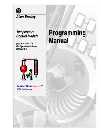
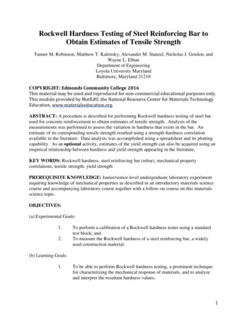
Chapter1Product OverviewDescriptionThe AIC advanced interface converter provides a communicationlink between various networked devices. The AIC interface converteris compatible with a variety of SLC and MicroLogix controllers andperipherals.Communication Port and Switch LocationsRS-485Communication Port(Phoenix Plug)RS-232 (8-pin mini-DIN)Communication PortCommunication-rateSelector SwitchRS-232 (DB-9, DTE)Communication PortDC Power-sourceSelector SwitchTerminals for external 24V dc powersupply and chassis ground.MicroLogix 1000, 1200, and 1500 controllers provide power to theAIC interface converter via the RS-232 8-pin mini-DIN port’s cable.However, if a MicroLogix controller is not connected to this port, a24V dc power supply connected to the converter’s external powerterminals is required. The dc power-source selector switch needs tobe set for your particular configuration.See Network Diagrams starting on page 21 for more details on how towire and configure the AIC interface converter.5Publication 1761-UM004B-EN-P - June 2006
6Product OverviewThe communication-rate selector switch is used to match thecommunication rate filter of the AIC interface converter to thenetwork communication rate. This switch does not change thenetwork communication rate and is normally left in the AUTOposition. In high noise environments, the communication-rate selectorswitch should be taken out of the AUTO mode and set to the samecommunication rate as the network.See Auto Transmit Delay on page 35 for more information oncommunication rates.Operation ModesThe AIC interface converter can be used in the following modes. Point-to-point isolator RS-232 to RS-485 isolator RS-232 to half-duplex user mode ASCII isolatorCommunication is established using hardware handshaking or autotransmit signals.Device CompatibilityThe AIC interface converter can be used to interconnect thefollowing devices. SLC 500, 5/01, 5/02, and 5/03 processors (channel 1)SLC 5/03, 5/04, and 5/05 processors (channel 0)MicroLogix controllersLogix controllers1756-DH485 ControlLogix moduleOperator interface devicesPersonal computer serial ports (or any 9-pin DTE serial port)ModemsTIPPublication 1761-UM004B-EN-P - June 2006You cannot connect the 1761-HHP-B30 Hand-held Programmerto the AIC advanced interface converter.
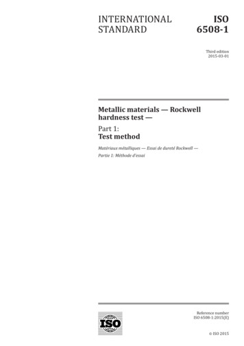
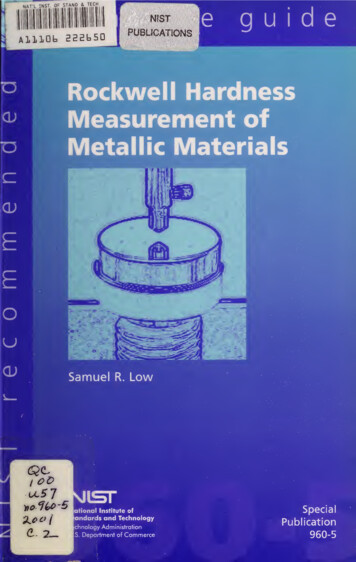
Product Overview7Node Address IdentificationThere is no nodeaddress associatedwith the networkport.The node address isconfigured in thedevice connectedwith this port.The node address isconfigured in thedevice connectedwith this port.Use this area to markthe node address ofeach connection.Publication 1761-UM004B-EN-P - June 2006
8Product OverviewPublication 1761-UM004B-EN-P - June 2006
Chapter2Installation and WiringCompliance to EuropeanUnion DirectivesIf this product has the CE mark it is approved for installation withinthe European Union and EEA regions. It has been designed and testedto meet the following directives.EMC DirectiveThis product is tested to meet Council Directive 89/336/EECElectromagnetic Compatibility (EMC) and the following standards, inwhole or in part, documented in a technical construction file. EN 50081-2 EMC – Generic Emission Standard, Part 2 – IndustrialEnvironment EN 50082-2 EMC – Generic Immunity Standard, Part 2 –Industrial EnvironmentThis product is intended for use in an industrial environment.Low Voltage DirectiveThis product is tested to meet Council Directive 73/23/EEC LowVoltage, by applying the safety requirements of EN 61131–2Programmable Controllers, Part 2 – Equipment Requirements andTests.For specific information required by EN 61131-2, see the appropriatesections in this publication, as well as the Industrial AutomationWiring and Grounding Guidelines, publication 1770-IN041.9Publication 1761-UM004B-EN-P - June 2006
10Installation and WiringSafety ConsiderationsThis equipment is suitable for use in Class I, Division 2, Groups A, B,C, D, or nonhazardous locations only.ATTENTIONExplosion Hazard —Substitution of components may impair suitability for Class I,Division 2.Do not replace components or disconnect equipment unlesspower is switched off and the area is known to benonhazardous.Do not connect or disconnect connectors or operate switcheswhile circuit is live unless the area is known to benonhazardous.This product must be installed in an enclosure. All cablesconnected to the product must remain in the enclosure or beprotected by conduit or other means.AIC interface converter must be operated from an externalpower source.All wiring must comply with N.E.C. articles 501, 502, 503,and/or C.E.C. Section 18-1J2, as appropriate.Use only the following communication cables and replacementconnectors in Class I, Division 2, hazardous locations.Communication Cables for Class 1, Div EnvironmentsEnvironment ClassificationCommunication CablesClass I, Division 2 Hazardous Environment1761-CBL-PM02 (Series C or later)1761-CBL-HM02 (Series C or later)1761-CBL-AM00 (Series C or later)1761-CBL-AP00 (Series C or later)2707-NC8 (Series B)2707-NC9 (Series B)2707-NC10 (Series B)2707-NC11 (Series B)1746-RT30 AIC ConnectorPublication 1761-UM004B-EN-P - June 2006
Installation and WiringMount t
1761-CBL-HM02 (Series C or later) 1761-CBL-AM00 (Series C or later) 1761-CBL-AP00 (Series C or later) 2707-NC8 (Series B) 2707-NC9 (Series B) 2707-NC10 (Series B) 2707-NC11 (Series B) 1746-RT30 AIC Connector. Publication 1761-UM004B-EN-P - June 2006 Installation and Wiring 11 Mount the AIC Advanced Interface Converter AIC interface converter. Interface Converter information. IMPORTANT .