Transcription
MAKING MODERN LIVING POSSIBLEInstruction ManualVLT HVAC Drive FC 1021.1–90 kWwww.danfoss.com/drives
VLT HVAC Drive Instruction ManualContentsContents1 Introduction41.1 Purpose of the Manual41.2 Additional Resources41.3 Document and Software Version41.4 Intended Use41.5 Block Diagram of the Adjustable Frequency Drive51.6 Enclosure Types and Power Ratings51.7 Approvals and Certifications51.8 Disposal Instruction52 Safety62.1 Safety Symbols62.2 Qualified Personnel62.3 Safety Precautions63 Mechanical Installation83.1 Unpacking83.2 Installation Environments113.3 Mounting114 Electrical Installation134.1 Safety Instructions134.2 EMC-compliant Installation134.3 Grounding134.4 Wiring Schematic144.5 Access164.6 Motor Connection164.7 AC Line Input Connection184.8 Control Wiring194.8.1 Control Terminal Types194.8.2 Wiring to Control Terminals204.8.3 Enabling Motor Operation (Terminal 27)214.8.4 Voltage/Current Input Selection (Switches)214.8.5 Safe Torque Off (STO)214.8.6 RS-485 Serial Communication22MG11AJ22 - Rev. 2013-09-13
VLT HVAC Drive Instruction ManualContents4.9 Installation Check List235 Commissioning245.1 Safety Instructions245.2 Applying Power245.3 Local Control Panel Operation255.4 Basic Programming285.4.1 Commissioning with SmartStart285.4.2 Commissioning via [Main Menu]285.4.3 Asynchronous Motor Set-up295.4.4 Permanent Magnet Motor Set-up295.4.5 Automatic Energy Optimization (AEO)305.4.6 Automatic Motor Adaptation (AMA)305.5 Checking Motor Rotation315.6 Local Control Test315.7 System Start-up325.8 Maintenance326 Application Set-up Examples337 Diagnostics and Troubleshooting397.1 Status Messages397.2 Warning and Alarm Types417.3 List of Warnings and Alarms427.4 Troubleshooting498 Specifications528.1 Electrical Data528.1.1 Line Power Supply 3x200–240 V AC538.1.2 Line Power Supply 3x380–480 V AC558.1.3 Line Power Supply 3x525–600 V AC578.1.4 Line Power Supply 3 x 525–690 V AC598.2 Line Power Supply628.3 Motor Output and Motor Data628.4 Ambient Conditions638.5 Cable Specifications638.6 Control Input/Output and Control Data64MG11AJ22 - Rev. 2013-09-13
VLT HVAC Drive Instruction ManualContents8.7 Connection Tightening Torques688.8 Fuse Specifications698.9 Power Ratings, Weight and Dimensions769 Appendix789.1 Symbols and Abbreviations789.2 Parameter Menu Structure78Index83MG11AJ22 - Rev. 2013-09-13
1 1VLT HVAC Drive Instruction ManualIntroduction1 Introduction1.1 Purpose of the Manual1.4 Intended UseThis instruction manual provides information for safe installation and commissioning of the adjustable frequency drive.The adjustable frequency drive is an electronic motorcontroller thatThis instruction manual is intended for use by qualifiedpersonnel.Read and follow the instruction manual in order to use theadjustable frequency drive safely and professionally, and payparticular attention to the safety instructions and generalwarnings. Keep this instruction manual available with theadjustable frequency drive at all times.1.2 Additional ResourcesOther resources are available to understand advancedadjustable frequency drive functions and programming. The Programming Guide provides greater detail onworking with parameters and many applicationexamples. The Design Guide provides detailed informationabout capabilities and functionality to design motorcontrol systems. Instructions for operation with optional equipment.Disclosure, duplication and sale of this document, as well ascommunication of its content, are prohibited unless explicitlypermitted. Infringement of this prohibition incurs liability fordamages. All rights reserved with regard to patents, utilitypatents and registered designs. VLT is a registeredtrademark. regulates motor speed in response to systemfeedback or to remote commands from externalcontrollers. A power drive system consists of theadjustable frequency drive, the motor andequipment driven by the motor. monitors aspects of system and motor status.Depending on configuration, the adjustable frequency drivecan be used in standalone applications or form part of alarger appliance or installation.The adjustable frequency drive is intended for use inresidential, industrial and commercial environments inaccordance with local laws and standards. Do not use theadjustable frequency drive in applications that do notcomply with specified designated operating conditions andenvironments.NOTICE!In a residential environment this product may cause radiointerference, in which case supplementary mitigationmeasures may be required.1.3 Document and Software VersionThis manual is regularly reviewed and updated. Allsuggestions for improvement are welcome. Table 1.1 showsthe document version and the corresponding softwareversion.EditionRemarksSoftware versionMG11AJxxReplaces MG11AIxx3.92Table 1.1 Document and Software Version4can be used for motor protection.MG11AJ22 - Rev. 2013-09-13
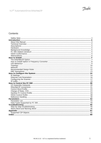
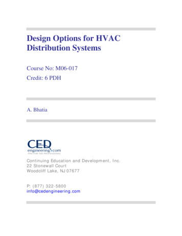
VLT HVAC Drive Instruction ManualIntroduction1.5 Block Diagram of the AdjustableFrequency DriveArea1 1Title User interface and externalcommands are monitored andperformed Status output and control canbe providedFigure 1.1 is a block diagram of the adjustable frequencydrive's internal components. See Table 1.2 for their functions.8Control circuitryFunctionsInput power, internalprocessing, output, and motorcurrent are monitored toprovide efficient operation andcontrolTable 1.2 Legend to Figure 1.1Figure 1.1 Adjustable Frequency Drive Block Diagram1.6 Enclosure Types and Power RatingsArea1TitleRectifier3DC bus453-phase AC line power supplyto the adjustable frequencydrive The rectifier bridge convertsthe AC input to DC current tosupply inverter power Intermediate DC bus circuithandles the DC current Filter the intermediate DCcircuit voltage Prove line transient protectionLine power input2DC reactorsCapacitor bankInverter7Output to motorReduce RMS currentRaise the power factorreflected back to the line Reduce harmonics on the ACinput Stores the DC power 6Functions Provides ride-throughprotection for short powerlossesConverts the DC into acontrolled PWM AC waveformfor a controlled variable outputto the motorFor enclosure types and power ratings of the adjustablefrequency drives, refer to 8.9 Power Ratings, Weight andDimensions.1.7 Approvals and CertificationsTable 1.3 Approvals and CertificationsMore approvals and certifications are available. Contact localDanfoss partner. The T7 (525–690 V) adjustable frequencydrives are not certified for UL.The adjustable frequency drive complies with UL508Cthermal memory retention requirements. For moreinformation, refer to the section Motor Thermal Protection inthe Design Guide.1.8 Disposal InstructionDo not dispose of equipment containingelectrical components together withdomestic waste.Collect it separately in accordance withlocal and currently valid legislation.Regulated 3-phase outputpower to the motorTable 1.4 Disposal InstructionMG11AJ22 - Rev. 2013-09-135
2 2SafetyVLT HVAC Drive Instruction Manual2 SafetyWARNING2.1 Safety SymbolsUNINTENDED START!The following symbols are used in this document.WARNINGIndicates a potentially hazardous situation which couldresult in death or serious injury.CAUTIONIndicates a potentially hazardous situation which couldresult in minor or moderate injury. It may also be used toalert against unsafe practices.NOTICE!Indicates important information, including situations thatmay result in damage to equipment or property.2.2 Qualified PersonnelCorrect and reliable transport, storage, installation, operationand maintenance are required for the trouble-free and safeoperation of the adjustable frequency drive. Only qualifiedpersonnel is allowed to install or operate this equipment.When the adjustable frequency drive is connected to ACline power, the motor may start at any time. Theadjustable frequency drive, motor, and any drivenequipment must be in operational readiness. Failure to bein operational readiness when the adjustable frequencydrive is connected to AC line power could result in death,serious injury, equipment or property damage.WARNINGDISCHARGE TIME!Adjustable frequency drives contain DC link capacitors thatcan remain charged even when the adjustable frequencydrive is not powered. To avoid electrical hazards,disconnect AC line power, any permanent magnet typemotors, and any remote DC link power supplies, includingbattery backups, UPS and DC link connections to otheradjustable frequency drives. Wait for the capacitors todischarge completely before performing any service orrepair work. The amount of waiting time is listed inTable 2.1. Failure to wait the specified time after power hasbeen removed before doing service or repair could resultin death or serious injury.Voltage [V]Qualified personnel is defined as trained staff, who areauthorized to install, commission, and maintain equipment,systems and circuits in accordance with pertinent laws andregulations. Additionally, the personnel must be familiar withthe instructions and safety measures described in thisdocument.2.3 Safety Precautions4715200–2401.1–3.7 kW5.5–45 kW380–4801.1–7.5 kW11–90 kW525–6001.1–7.5 kW525–69011–90 kW1.1–7.5 kW11–90 kWHigh voltage may be present even when the warning LEDindicator lights are off.Table 2.1 Discharge TimeWARNINGWARNINGHIGH VOLTAGE!Adjustable frequency drives contain high voltage whenconnected to AC line power. Installation, start-up, andmaintenance must be performed by qualified personnelonly. Failure to perform installation, start-up, andmaintenance by qualified personnel could result in deathor serious injury.6Minimum waiting time [minutes]LEAKAGE CURRENT HAZARD!Leakage currents are higher than 3.5 mA. It is the responsibility of the user or certified electrical installer to ensurecorrect grounding of the equipment. Failure to ground theadjustable frequency drive properly could result in deathor serious injury.MG11AJ22 - Rev. 2013-09-13
SafetyVLT HVAC Drive Instruction ManualWARNING2 2EQUIPMENT HAZARD!Rotating shafts and electrical equipment can be hazardous.All electrical work must conform to national and localelectrical codes. Installation, start-up, and maintenance areperformed only by trained and qualified personnel. Failureto follow these guidelines could result in death or seriousinjury.WARNINGWINDMILLING!Unintended rotation of permanent magnet motors causesa risk of personal injury and equipment damage. Ensurepermanent magnet motors are blocked to preventunintended rotation.CAUTIONPOTENTIAL HAZARD IN THE EVENT OF INTERNALFAILURE!Risk of personal injury when the adjustable frequencydrive is not properly closed. Before applying power, ensureall safety covers are in place and securely fastened.MG11AJ22 - Rev. 2013-09-137
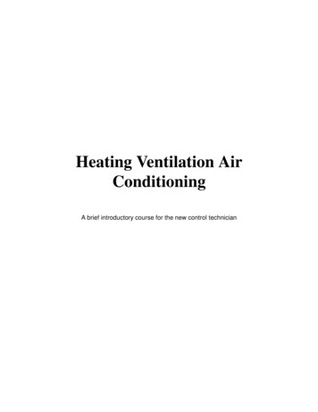
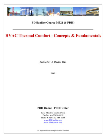
3 Mechanical Installation3.1 Unpacking3.1.1 Items Supplied 123456Check the packaging and the adjustable frequencydrive visually for damage caused by inappropriatehandling during shipment. File any claim fordamage with the carrier. Retain damaged parts forclarification.Make sure the items supplied and the informationon the nameplate correspond to the order confirmation.VLTRHVAC Drivewww.danfoss.comT/C: FC-102P3K0T4Z55H1UGCXXXSXXXXAXBXCXXXXDXP/N: 131U3930S/N: 010102G2903.0kW(400V) / 4.0HP(460V)IN: 3x380-480V 50/60Hz 6.5/5.7AOUT: 3x0-Vin 0-590Hz 7.2/6.3AooType 12 / IP55 Tamb.45 C/113 F*1 3 1 U 3 9 3 0 0 1 0 1 0 2 G 2 9 0 *10130BD511.103 3VLT HVAC Drive Instruction ManualMechanical Installation1Type code2Order number3Power rating4Input voltage, frequency and current (at low/high voltages)5Output voltage, frequency and current (at low/highvoltages)6Enclosure type and IP rating7Maximum ambient temperature8Certifications9Discharge time (Warning)10Serial numberTable 3.1 Legend to Figure 3.1NOTICE!Do not remove the nameplate from theadjustable frequency drive (loss of warranty).83.1.2 Storage7Ensure that requirements for storage are fulfilled. Refer to8.4 Ambient Conditions for further details.MADE IN DENMARKListed 76X1 E134261 Ind. Contr. Eq.9CAUTION:See manual for special condition/mains fuse voir manual de conditions speclales/fusiblesWARNING:Stored charge, wait 4 min. attendez 4 min.Charge residuelle,Figure 3.1 Product Nameplate (Example)8MG11AJ22 - Rev. 2013-09-13
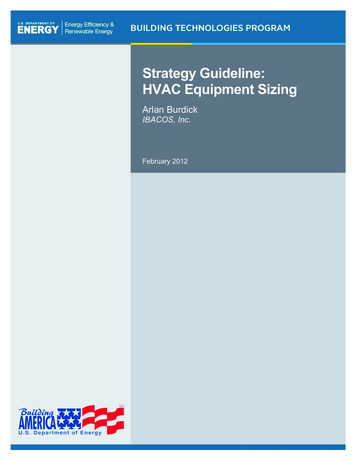
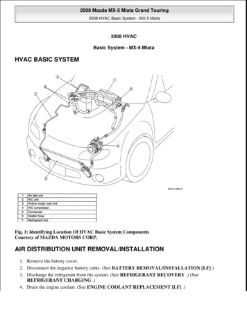
VLT HVAC Drive Instruction ManualMechanical Installation130BB492.103.1.3 Product Overview123 334185171661587891410111312Figure 3.2 Exploded View Enclosure Type A, IP201Local control panel (LCP)10Motor output terminals 96 (U), 97 (V), 98 (W)2RS-485 serial bus connector ( 68, -69)11Relay 2 (01, 02, 03)3Analog I/O connector12Relay 1 (04, 05, 06)4LCP input plug13Brake (-81, 82) and load sharing (-88, 89) terminals5Analog switches (A53), (A54)14Line power input terminals 91 (L1), 92 (L2), 93 (L3)6Cable shield connector15USB connector7Decoupling plate16Serial bus terminal switch8Grounding clamp (PE)17Digital I/O and 24 V power supply9Shielded cable grounding clamp and strain relief18CoverTable 3.2 Legend to Figure 3.2MG11AJ22 - Rev. 2013-09-139
VLT HVAC Drive Instruction Manual13121123 310DC-DC 106 05 0403 02 019861683942Remove jumper to activate505354Safe StopMax. 24 Volt !123131819272932332074651718FAN MOUNTINGQDF-30191615Figure 3.3 Exploded View Enclosure Types B and C, IP55 and IP661Local control panel (LCP)11Relay 2 (04, 05, 06)2Cover12Lifting ring3RS-485 serial bus connector13Mounting slot4Digital I/O and 24 V power supply14Grounding clamp (PE)5Analog I/O connector15Cable shield connector6Cable shield connector16Brake terminal (-81, 82)7USB connector17Load sharing terminal (DC bus) (-88, 89)8Serial bus terminal switch18Motor output terminals 96 (U), 97 (V), 98 (W)9Analog switches (A53), (A54)19Line power input terminals 91 (L1), 92 (L2), 93 (L3)10Relay 1 (01, 02, 03)Table 3.3 Legend to Figure 3.310MG11AJ22 - Rev. 2013-09-1314130BB493.10Mechanical Installation
Mechanical InstallationVLT HVAC Drive Instruction ManualNOTICE!130BD528.103.2 Installation EnvironmentsaIn environments with airborne liquids, particles, orcorrosive gases, ensure that the IP/Type rating of theequipment matches the installation environment. Failure tomeet requirements for ambient conditions can reducelifetime of the adjustable frequency drive. Ensure thatrequirements for air humidity, temperature and altitudeare met.Vibration and ShockThe adjustable frequency drive complies with requirementsfor units mounted on the walls and floors of productionpremises, as well as in panels bolted to walls or floors.For detailed ambient conditions specifications, refer to8.4 Ambient Conditions.a3.3 MountingNOTICE!Figure 3.4 Top and Bottom Cooling ClearanceImproper mounting can result inoverheating and reduced performance.Cooling Ensure that top and bottom clearance for aircooling is provided. See Figure 3.4 for clearancerequirements.EnclosureA2-A5B1-B4C1, C3C2, C4a (mm)100200200225Table 3.4 Minimum Airflow Clearance RequirementsLifting To determine a safe lifting method, check theweight of the unit, see 8.9 Power Ratings, Weightand Dimensions. Ensure that the lifting device is suitable for the task. If necessary, plan for a hoist, crane, or forklift withthe appropriate rating to move the unit.For lifting, use hoist rings on the unit, whenprovided.Mounting1.Ensure that the strength of the mounting locationsupports the unit weight. The adjustable frequencydrive allows side-by-side installation.2.Mount the unit vertically on a solid flat surface oron the optional backplate.3.Use the slotted mounting holes on the unit for wallmounting, when provided.MG11AJ22 - Rev. 2013-09-13113 3
Mechanical InstallationVLT HVAC Drive Instruction Manual130BD504.10Mounting with backplate and railings3 3Figure 3.5 Proper Mounting with BackplateNOTICE!Backplate is required when mounted on railings.12MG11AJ22 - Rev. 2013-09-13
Electrical InstallationVLT HVAC Drive Instruction Manual4 Electrical InstallationSee 8.1 Electrical Data and 8.5 Cable Specifications forrecommended wire sizes and types.4.1 Safety InstructionsTo obtain an EMC-compliant installation, follow theinstructions provided in 4.3 Grounding, 4.4 Wiring Schematic,4.6 Motor Connection and 4.8 Control Wiring.WARNINGINDUCED VOLTAGE!Induced voltage from output motor cables that runtogether can charge equipment capacitors even with theequipment turned off and locked out. Failure to run outputmotor cables separately or use shielded cables or metalconduits could result in death or serious injury.CAUTIONDC CURRENT HAZARD!A DC current in the protective grounding conductor can becaused by the adjustable frequency drives. When a residualcurrent-operated protective or monitoring device (RCD/RCM) is used for protection, only an RCD or RCM of Type Bis allowed.NOTICE!The adjustable frequency drive is supplied withClass 20 motor overload protection.Overcurrent Protection: 4 44.2 EMC-compliant InstallationSee 2 Safety for general safety instructions.Additional protective equipment such as shortcircuit protection or motor thermal protectionbetween adjustable frequency drive and motor isrequired for applications with multiple motors.Input fusing is required to provide short-circuit andovercurrent protection. If not factory-supplied, fusesmust be provided by the installer. See maximumfuse ratings in 8.8 Fuse Specifications.Wire Type and Ratings All wiring must comply with local and nationalregulations regarding cross-section and ambienttemperature requirements. Power connection wire recommendation: minimum75 C rated copper wire.4.3 GroundingWARNINGLEAKAGE CURRENT HAZARD!Leakage currents are higher than 3.5 mA. It is the responsibility of the user or certified electrical installer to ensurecorrect grounding of the equipment. Failure to ground theadjustable frequency drive properly could result in deathor serious injury.For electrical safety Ground the adjustable frequency drive properly inaccordance with applicable standards anddirectives. Use a dedicated ground wire for input power,motor power and control wiring. Do not ground one adjustable frequency drive toanother in a “daisy chain” fashion. Keep the ground wire connections as short aspossible. Do not use pigtails. Follow the motor manufacturer wiringrequirements.Minimum cable cross-section: 10 mm2 (or 2 ratedground wires terminated separately).For EMC-compliant installation Establish electrical contact between cable shieldand adjustable frequency drive enclosure by usingmetal cable connectors or by using the clampsprovided on the equipment. Use high-strand wire to reduce electricalinterference.MG11AJ22 - Rev. 2013-09-1313
NOTICE!POTENTIAL EQUALIZATION!Electrical interference risks disturbing the entire installation, when the ground potential between the adjustablefrequency drive and the system is different. To avoid electrical interference, install equalizing cables between thesystem components. Recommended cable cross-section: 16 mm2.4.4 Wiring Schematic3-phasepowerinputDC bus 10 V DCSwitch ModePower Supply10 V DC 24 V DC15 mA 130/200 mA88 (-)89 ( )50 ( 10 V OUT) - ONA54ON54 (A IN)relay1ON 0/4-20 mAOFF 0/-10 V DC 10 V DC03relay2010613 ( 24 V OUT)24 V (NPN)0 V (PNP)0419 (D IN)24 V (NPN)0 V (PNP)(COM A OUT) 39(D IN/OUT)24 V (NPN)0 V (PNP)24 VS801ON24 V1 2(D IN/OUT)400 V AC, 2 AAnalog Output0/4-20 mA(A OUT) 420V29240 V AC, 2 A05P 5-0018 (D IN)27240 V AC, 2 A0212 ( 24 V OUT)(COM D IN)Brakeresistor(R-) 8155 (COM A IN)20Motor(R ) 82-A5353 (A IN)1 20/-10 V DC 10 V DC0/4-20 mA(U) 96(V) 97(W) 98(PE) 991 20/-10 V DC 10 V DC0/4-20 mA91 (L1)92 (L2)93 (L3)95 PE130BD552.114 4VLT HVAC Drive Instruction ManualElectrical InstallationON TerminatedOFF Open5V24 V (NPN)0 V (PNP)S8010V32 (D IN)24 V (NPN)0 V (PNP)33 (D IN)24 V (NPN)0 V (PNP)RS-485Interface0VRS-485(N RS-485) 69(P RS-485) 68(COM RS-485) 61*37 (D IN)**: Chassis: GroundFigure 4.1 Basic Wiring SchematicA Analog, D Digital*Terminal 37 (optional) is used for Safe Torque Off. For Safe Torque Off installation instructions, refer to the Safe Torque OffInstruction Manual for Danfoss VLT Adjustable Frequency Drives.**Do not connect cable shield.14MG11AJ22 - Rev. 2013-09-13
130BD529.10VLT HVAC Drive Instruction ManualElectrical Installation264 41345910L1L2L3PEUVWPE87Figure 4.2 EMC--compliant Electrical Connection1PLC6Shielded cable2Adjustable frequency drive7Motor, 3-phase and PE3Output contactor8Line power, 3-phase and reinforced PE4Grounding rail (PE)9Control wiring5Cable insulation (stripped)10Equalizing min. 16 mm2 (0.025 in)Table 4.1 Legend to Figure 4.2MG11AJ22 - Rev. 2013-09-1315
VLT HVAC Drive Instruction Manual130BT334.10NOTICE!EMC INTERFERENCE!Use separated shielded cables for input power, motorwiring and control wiring, or run cables in three separatemetallic conduits. Failure to isolate power, motor andcontrol wiring can result in unintended behavior orreduced performance. Minimum 200 mm (7.9 in) clearancebetween control cables, motor and line power.4.5 Access Remove cover with a screwdriver (See Figure 4.3) orby loosening attaching screws (See Figure 4.4).130BT248.104 4Electrical InstallationFigure 4.4 Access to Wiring for IP55 and IP66 EnclosuresSee Table 4.2 before tightening the 2.2No screws to tighten for A2/A3/B3/B4/C3/C4.Table 4.2 Tightening Torques for Covers [Nm]Figure 4.3 Access to Wiring for IP20 and IP21 Enclosures4.6 Motor ConnectionWARNINGINDUCED VOLTAGE!Induced voltage from output motor cables that runtogether can charge equipment capacitors even with theequipment turned off and locked out. Failure to run outputmotor cables separately or use shielded cables or metalconduits could result in death or serious injury.16 Comply with local and national electrical codes forcable sizes. For maximum wire sizes, see8.1 Electrical Data. Follow the motor manufacturer wiringrequirements. Motor wiring knockouts or access panels areprovided at the base of IP21 (NEMA1/12) andhigher units.MG11AJ22 - Rev. 2013-09-13
VLT HVAC Drive Instruction ManualElectrical Installation Do not wire a starting or pole-changing device (e.g.,Dahlander motor or slip ring induction motor)between the adjustable frequency drive and themotor.Figure 4.6, Figure 4.7, Figure 4.8 and Figure 4.9 represent linepower input, motor, and grounding for basic adjustablefrequency drives. Actual configurations vary with unit typesand optional equipment.2.Position the stripped wire under the cable clamp toestablish mechanical fixation and electrical contactbetween cable shield and ground.3.91Connect ground wire to the nearest groundingterminal in accordance with grounding instructionsprovided in 4.3 Grounding, see Figure 4.5.Connect the 3-phase motor wiring to terminals 96(U), 97 (V), and 98 (W), see Figure 4.5.5.Tighten terminals in accordance with theinformation provided in 8.7 Connection TighteningTorques.V9697L29293AINL3S DC99BR- BMOU TORV WFigure 4.6 Motor, Line Power and Ground Wiring for EnclosureTypes A2 and A3130BD513.10UW98130BD531.104.ML1RELAY 2Strip a section of the outer cable insulation.RELAY 11.130BD577.10ProcedureUFigure 4.5 Motor ConnectionV96W9798Figure 4.7 Motor, Line Power and Ground Wiring for EnclosureTypes A4 and A5MG11AJ22 - Rev. 2013-09-13174 4
VLT HVAC Drive Instruction Manual88DC91L192L293L39596U97V89DC 81R-130BA390.11Electrical Installation8R 98W4.7 AC Line Input Connection Size wiring based upon the input current of theadjustable frequency drive. For maximum wire sizes,see 8.1 Electrical Data. Comply with local and national electrical codes forcable sizes.994 4ProcedureConnect 3-phase AC input power wiring toterminals L1, L2, and L3 (see Figure 4.10).2.Depending on the configuration of the equipment,input power will be connected to the line powerinput terminals or the input disconnect.3.Ground the cable in accordance with groundinginstructions provided in 4.3 Grounding.4.When supplied from an isolated line power source(IT line power or floating delta) or TT/TN-S linepower with a grounded leg (grounded delta),ensure that 14-50 RFI 1 is set to OFF to avoiddamage to the intermediate circuit and to reduceground capacity currents in accordance with IEC61800-3.130BB477.10Figure 4.8 Motor, Line Power and Ground Wiring for EnclosureTypes B and C Using Shielded Cable1.9592L293L396U97V91R-9R 130BT336.108889DC DC-91L199W99L3L2L 1 2 93991Figure 4.9 Motor, Line Power and Ground Wiring for EnclosureTypes B and C Using Conduit18Figure 4.10 Connecting to AC Line PowerMG11AJ22 - Rev. 2013-09-13
VLT HVAC Drive Instruction ManualElectrical Installation Connector 3 provides two analog inputs, oneanalog output, 10 V DC supply voltage, andcommons for the inputs and output Connector 4 is a USB port available for use with theMCT 10 Set-up Software4.8 Control Wiring Isolate control wiring from high power componentsin the adjustable frequency drive. When the adjustable frequency drive is connectedto a thermistor, ensure that the thermistor controlwiring is shielded and reinforced/double insulated.A 24 V DC supply voltage is recommended.Terminal descriptionTerminalParameterDefaultSetting12, 13- 24 V DC185-10[8] Start195-11[0] Nooperation325-14[0] Nooperation335-15[0] Nooperation275-12[2] Coastinverse295-13[14] JOG20-37-39-426-50Speed 0 High LimitProgrammable analogoutput. The analogsignal is 0–20 mA or 4–20 mA at a maximum of50- 10 V DC10 V DC analog supplyvoltage. 15 mAmaximum commonlyused for potentiometeror thermistor.536-1Reference546-2FeedbackAnalog input. Selectablefor voltage or current.Switches A53 and A54select mA or V.130BB921.11Figure 4.11 shows the removable adjustable frequency driveconnectors. Terminal functions and default settings aresummarized in Table 4.3.341130BB931.10112 13 18 19 27 29 32 33 20 37Safe TorqueOff (STO) Digital inputs.Selectable for digitalinput and output.Default setting is input.Safe input (optional).Used for STO.Analog Inputs/Outputs339 42 50 53 54 55Common for analogoutput.Figure 4.12 Terminal Numbers 24 V DC supply voltage.Maximum outputcurrent is 200 mA totalfor all 24 V loads. Usablefor digital inputs andexternal transducers.Common for digitalinputs and 0 V potentialfor 24 V supply.Figure 4.11 Control Terminal Locations261 68 69DescriptionDigital Inputs/Outputs4.8.1 Control Terminal Types24 4500 Ω.Connector 1 provides four programmable digitalinputs terminals, two additional digital terminalsprogrammable as either input or output, a 24 V DCterminal supply voltage, and a common for optionalcustomer supplied 24 V DC voltage.Connector 2 terminals ( )68 and (-)69 are for anRS-485 serial communications connectionMG11AJ22 - Rev. 2013-09-1319
VLT HVAC Drive Instruction Manual55-61-Common for analoginput.Serial Communication4 468 ( )8-369 (-)8-3Integrated RC filter forcable shield. ONLY forconnecting the shieldwhen experiencing EMCproblems.RS-485 Interface. Acontrol card switch isprovided for terminationresistance.4.8.2 Wiring to Control TerminalsControl terminal connectors can be unplugged from theadjustable frequency drive for ease of installation, as shownin Figure 4.11.NOTICE!Keep control wires as short as possible and separate fromhigh power cables to minimize interference.1.Relays01, 02, 035-40 [0][9] Alarm04, 05, 065-40 [1][5] RunningForm C relay output.Usable for AC or DCvoltage and resistive orinductive loads.Open the contact by inserting a small screwdriverinto the slot above the contact and push thescrewdriver slightly upwards.130BD546.10Electrical Installation12 13 18 19 27 29Table 4.3 Terminal Description3233Additional terminals: 1Terminals located on built-in optional equipment.See the manual provided with the equipmentoption.mm2 form C relay outputs. Location of the outputsdepends on adjustable frequency drive configuration.10 2Figure 4.13 Connecting Control Wires2.Insert the bared control wire into the contact.3.Remove the screwdriver to fasten the control wireinto the contact.4.Ensure the contact is firmly established and notloose. Loose control wiring can be the source ofequipment faults or less than optimal operation.See 8.5 Cable Specifications for control terminal wiring sizesand 6 Application Set-up Examples for typical control wiringconnections.20MG11AJ22 - Rev. 2013-09-13
VLT HVAC Drive Instruction Manual4.8.3 Enabling Motor Operation (Terminal 27)A jumper wire may be required between terminal 12 (or 13)and terminal 27 for the adjustable frequency drive to operatewhen using factory default programming values.Digital input terminal 27 is designed to receive an24 V DC external interlock command. In manyapplications, the user wires an external interlockdevice to terminal 27 When no interlock device is used, wire a jumperbetween control terminal 12 (recommended) or 13to terminal 27. This provides an internal 24 V signalon terminal 27. No signal present prevents the unit from operating.1.Remove the local control panel (see Figure 4.14).2.Remove any optional equipment covering theswitches.3.Set switches A53 and A54 to select the signal type.U selects voltage, I selects current.When the status line at the bottom of the LCPreads AUTO REMOTE COAST, this indicates that theunit is ready to operate but is missing an inputsignal on terminal 27.When factory installed optional equipment is wiredto terminal 27, do not remove that wiring1 Remove power to the adjustable frequencydrive before changing switch positions.2N O NOTICE!130BD530.10Electrical InstallationNOTICE!The adjustable frequency drive cannot operate without asignal on terminal 27 unless terminal 27 is re-programmed.BUSTER.OFF-ON4.8.4 Voltage/Current Input Selection(Switches)The analog input terminals 53 and 54 allow setting of inputsignal to voltage (0–10 V) or current (0/4–20 mA).Default parameter settings: Terminal 53: speed reference signal in open-loop(see 16-61 Terminal 53 Switch Setting). Terminal 54: feedback signal in closed-loop (see16-63 Terminal 54 Switch Setting).A53 A54U- I U- IVLTFigure 4.14 Location of Terminals 53 and 54 Switches4.8.5 Safe Torque Off (STO)To run Safe Torque Off, additional wiring for the adjustablefrequency drive is required, refer to Safe Torque OffInstru
the Design Guide. 1.8 Disposal Instruction Do not dispose of equipment containing electrical components together with domestic waste. Collect it separately in accordance with local and currently valid legislation. Table 1.4 Disposal Instruction Introduction VLT HVAC