Transcription
Strategy Guideline:HVAC Equipment SizingArlan BurdickIBACOS, Inc.February 2012
This report received minimal editorial review at NRELNOTICEThis report was prepared as an account of work sponsored by an agency of theUnited States government. Neither the United States government nor any agencythereof, nor any of their employees, makes any warranty, express or implied, orassumes any legal liability or responsibility for the accuracy, completeness, orusefulness of any information, apparatus, product, or process disclosed, or representsthat its use would not infringe privately owned rights. Reference herein to any specificcommercial product, process, or service by trade name, trademark, manufacturer, orotherwise does not necessarily constitute or imply its endorsement, recommendation,or favoring by the United States government or any agency thereof. The views andopinions of authors expressed herein do not necessarily state or reflect those of theUnited States government or any agency thereof.Available electronically at http://www.osti.gov/bridgeAvailable for a processing fee to U.S. Department of Energyand its contractors, in paper, from:U.S. Department of EnergyOffice of Scientific and Technical InformationP.O. Box 62Oak Ridge, TN 37831-0062phone: 865.576.8401fax: 865.576.5728email: mailto:reports@adonis.osti.govAvailable for sale to the public, in paper, from:U.S. Department of CommerceNational Technical Information Service5285 Port Royal RoadSpringfield, VA 22161phone: 800.553.6847fax: 703.605.6900email: orders@ntis.fedworld.govonline ordering: http://www.ntis.gov/ordering.htmPrinted on paper containing at least 50% wastepaper, including 20% postconsumer waste
Strategy Guideline:HVAC Equipment SizingPrepared for:Building AmericaBuilding Technologies ProgramOffice of Energy Efficiency and Renewable EnergyU.S. Department of EnergyPrepared by:Arlan BurdickIBACOS, Inc.2214 Liberty AvenuePittsburgh, Pennsylvania 15222NREL Technical Monitor: Michael GestwickPrepared under Subcontract No. KNDJ-0-40341-02February 2012i
[This page left blank]ii
ContentsList of Figures . ivList of Tables . vDefinitions . viExecutive Summary . vii1 Introduction . 12 Overview . 3342.1 Design Conditions .62.2 Preliminary Equipment Selection .72.3 Manufacturer Data Tables.82.4 Cooling Equipment Capacity Sensitivities .92.5 Estimated Target Cubic Feet per Minute .122.6 Efficiency Considerations .13Chicago House Example . 153.1 Cooling Equipment Selection .153.2 Furnace Selection .20Orlando House Example . 244.1 Air Source Heat Pump Selection .264.2 Heat Pump Cooling Capacity Selection.274.3 Heat Pump Heating Capacity Selection .305 Conclusion . 35References . 36iii
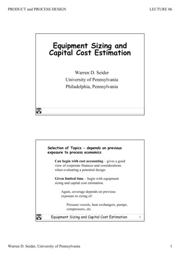
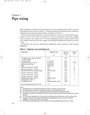
List of FiguresFigure 1. Design information from ACCA Manual J—Residential Load Calculation. . 1Figure 2. Upflow furnace scenario as in the Chicago House. . 4Figure 3. Heat pump scenario as in the Orlando House. . 5Figure 4. General steps to equipment selection. . 6Figure 5. Design information needed. . 7Figure 6. Fictitious example: detailed cooling capacities table. . 8Figure 7. Airflow sensitivity graph (from Manual S, Figure 3-1). 10Figure 8. OAT sensitivity graph (from Manual S, Figure 3-1). . 10Figure 9. Indoor EWB sensitivity graph (from Manual S, Figure 3-1). . 11Figure 10. Indoor EDB temperature sensitivity graph (from Manual S, Figure 3-1). . 11Figure 11. TD value table (from Manual S, Table 1-4). 12Figure 12. Chicago House BEopt 1.1 output. . 13Figure 13. Orlando House BEopt 1.1 output. . 14Figure 14. Cooling equipment selection step 1. . 15Figure 15. Chicago House design information. . 15Figure 16. Cooling equipment selection step 2. . 16Figure 17. Cooling equipment selection step 3. . 16Figure 18. Wet-bulb temperature on sea-level psychometric chart. . 17Figure 19. Cooling equipment selection step 4. . 17Figure 20. Fictitious example: detailed cooling capacities table, 800 cfm. . 18Figure 21. Fictitious example: detailed cooling capacities table, 715 cfm and 750 cfm. . 19Figure 22. Interpolation table for capacities at 89 F outdoor design temperature. . 19Figure 23. Furnace selection steps. . 20Figure 24. Furnace specification chart. . 21Figure 25. Air delivery performance table. . 22Figure 26. Fictitious furnace performance example. . 22Figure 27. Air delivery performance table for the Chicago House. . 23Figure 28. Air source heat pump selection steps. . 24Figure 29. Development of balance-point diagram. . 25Figure 30. Air source heat pump selection step 1. . 26Figure 31. Orlando House design information. . 26Figure 32. Air source heat pump selection step 2. . 27Figure 33. Air source heat pump selection step 3. . 28Figure 34. Wet-bulb temperature on sea-level psychometric chart. . 28Figure 35. Cooling equipment selection step 4. . 29Figure 36. Fictitious example: detailed heat pump cooling capacities table, 700 cfm. . 30Figure 37. Interpolation table for cooling capacities at 92 F outdoor design temperature. . 30Figure 38. Cooling equipment selection step 5. . 31Figure 39. Heat pump heating performance table at 700 cfm. 31Figure 40. Interpolation table for heating capacities at 38 F outdoor design temperature. . 32Figure 41. Cooling equipment selection step 6. . 32Figure 42. Balance-point diagram for the Orlando House. . 33Figure 43. Fan coil nomenclature. . 34* Unless otherwise noted, all figures were created by IBACOS.iv
List of TablesTable 1. ACCA Manual J Heating and Cooling Loads. . 6v
DefinitionsACCAAir Conditioning Contractors of AmericaAFUEAnnual Fuel Utilization EfficiencyAHRIAir-Conditioning, Heating, and Refrigeration InstituteARIAir-Conditioning and Refrigeration InstituteASHRAEAmerican Society of Heating, Refrigerating, and AirConditioning EngineersBEoptBuilding Energy Optimization (software)cfmCubic Feet per MinuteEDBEntering Dry-BulbEWBEntering Wet-BulbHSPFHeating Seasonal Performance FactorHVACHeating, Ventilation, and Air ConditioningIECCInternational Energy Conservation CodeLATTemperature of Air Leaving the Cooling CoilOATOutdoor Air TemperatureSEERSeasonal Energy Efficiency RatioSHRSensible Heat RatioTDRoom-Air to Supply-Air Temperature Differencevi
Executive SummaryRight-sizing of a residential heating, ventilation, and air conditioning (HVAC) system involvesthe selection of equipment and the design of the air distribution system to meet the accuratepredicted heating and cooling loads of a house. This Strategy Guideline follows the AirConditioning Contractors of America (ACCA) Manual S—Residential Equipment Selection(Manual S) (Rutkowski 1995) to describe what information is needed and how to use thatinformation to initially select the equipment for a properly designed HVAC system. Equipmentselection and duct design are iterative processes where the capacity of the equipment is balancedagainst the design of the distribution system.This Strategy Guide describes the equipment selection of a split system air conditioner andfurnace for an example house in Chicago, Illinois, as well as a heat pump system for an examplehouse in Orlando, Florida. The required heating and cooling load information for the twoexample houses was developed by Burdick (2011).Selection of the equipment can have a substantial impact on the efficiency and operating costs ofthe system. For the example houses presented in this Strategy Guide, a 92.5% AFUE (annual fuelutilization efficiency) furnace with a 16 SEER (seasonal energy efficiency ratio) air conditionerwas the system chosen for the Chicago House and a 9.2 HSPF (heating seasonal performancefactor)/16 SEER heat pump for the Orlando House.With an accurate estimate of the heating and cooling loads completed, the HVAC systemdesigner can begin the equipment selection procedure. It is the system designer’s responsibilityto select the heating and cooling equipment and to verify that the selected pieces of equipmentmeet the following: The total cooling load, composed of both the sensible load (temperature) and the latentload (humidity) The heating load The blower capacity (in cubic feet per minute [cfm]) to meet the volume of air cfm rangeneeded.The general steps to equipment selection are:1. Determine accurate heating and cooling loads.2. Select cooling equipment.3. Select heating equipment.4. Design the ducts.It is worth noting that the design of a space conditioning system is an iterative process. Once aduct system configuration and preliminary design are completed, different equipment may needto be selected to achieve the proper airflow to satisfy the room-by-room heating and coolingloads.vii
1IntroductionThe heating, ventilation, and air conditioning (HVAC) system is arguably the most complexsystem installed in a house and is a subs
Right-sizing the HVAC system begins with an accurate understanding of the heating and cooling loads on a space; however, a full HVAC design involves more than just the load estimate calculation—the load calculation is the first step of the iterative HVAC design procedure. The iterative nature of HVAC design is illustrated in . Figure 1, along with the Strategy Guidelines that cover the .