Transcription
International Journal on Electrical Engineering and Informatics ‐ Volume 6, Number 1, March 2014Rectangular to Parallel Plate Waveguide Transition and Its TaperingEffect for Microwave Devices CharacterizationAchmad Munir1, Ananto Eka Prasetiadi1,2, Levy Olivia Nur1,3,Sugihartono1, and Adit Kurniawan11Radio Telecommunication and Microwave LaboratorySchool of Electrical Engineering and InformaticsInstitut Teknologi Bandung, Indonesia, Jalan Ganesha 10, Bandung 40132, Indonesia2Institut für Mikrowellentechnik und PhotonikTechnische Universität Darmstadt, Merckstr. 25, 64283 Darmstadt, Germany3Telkom Engineering SchoolTelkom University, Jalan Telekomunikasi, Dayeuh Kolot, Bandung 40257, Indonesiamunir@ieee.orgAbstract: The experimental characterization in exploiting the property of microwavedevices is an essential complement to theoretical and/or simulation works. Thus, theneed of instrument for the characterization is becoming unavoidable thing to beestablished. This paper reports the development of test-fixture in form of a parallel platewaveguide (PPW) to characterize the reflectivity and/or transmittivity of microwavedevice whereby the property of reflection and/or transmission can be achieved undernormal incidence. Since the PPW is excited using a rectangular waveguide, a transitionsection which connects the rectangular waveguide and the PPW needs to be investigatedto have an optimum performance required for microwave devices characterization. Thetapering effect of transition section is examined and analyzed numerically in yieldingthe influences to the test-fixture performance. Here, a WR248 type rectangularwaveguide which has working frequency of 2.60GHz to 3.95GHz for TE10 mode is usedas coaxial-to-waveguide transducer for exciting the PPW. The result shows that thelinear-tapered transition has better performance in term of bandwidth compared to thestep-tapered one. In addition, the discussions of taper length and number of step-taperedtransition related to the performance of test-fixture as well as the experimentalcharacterization for linear-tapered transition are also presented.Keywords: coax-to-waveguide transducer, linear-tapered transition section, microwavedevices, parallel plate waveguide, rectangular waveguide, step-tapered transitionsection.1. IntroductionOne of the important things in the design of microwave devices is the experimentalcharacterization to compare and verify the characteristic of realized devices to comply with thedesign or specification. Unfortunately, for some devices with infinite number of structures orunit cell such as frequency selective surfaces (FSS), there is often impossible to directlymeasure their characteristics, i.e. reflectivity or transmittivity, especially at microwavefrequency or the higher one. Some methods by using close-sided waveguide simulators havebeen applied to obtain the properties of array elements and FSS [1]-[4]. However, due to thenature of these simulators they suffer from the problem that the device under test (DUT) couldbe characterized only for certain angle of incidence which is positioned away from the path ofnormal incidence. To cope with this problem, a parallel plate waveguide (PPW) method wasimplemented as an alternative technique [5]-[6]. By using this method, the characterization ofinfinite number of structures can be carried out using a finite one since the walls of PPWbehave as pairs of image planes.Received: October 31st, 2013. Accepted: February 23rd, 2014181
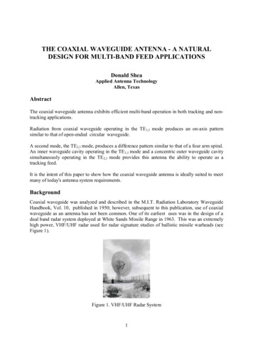
Achmad Munir, et alBased upon the application of finite element modeling technique, the concept of PPW hasbeen applied in many microwave measurements [5]-[7]. Instead of only as an experimentaltest-fixture such as for measuring the reflectivity and/or transmittivity, the PPW method issometimes used as a theoretical means of evaluating the characteristics of several structures ordevices. Since the method has the capability to make an enclosed structure which appears as aninfinitely periodic environment [8], therefore it has possibility to be implemented forperforming laboratory measurement under controlled conditions. In principle, to be able forexperimental characterization, the PPW is usually is illuminated by using a specific mode ofplane wave which is excited from a wave exciter. The coaxial-to-waveguide transducer iscommonly used as a wave exciter due to the advantage in ease of construction and excess ofperformance [5], [7]. Whilst in [6], for simplifying the high frequency measurement the PPWapplies coaxial wave excitation as a complement of coaxial-to-waveguide transducer.In order to have an optimum performance of PPW-based test-fixture, in place of directlyconnecting the rectangular waveguide that acts as a wave exciter to the PPW [5], a transitionsection between the waveguide and the PPW is required to minimize the reflection loss whichoccurs due to the impedance mismatch of both. The similar section referred as converter hasalso been used to connect a circular waveguide and a coaxial-to-waveguide transducer in formof rectangular shape to overcome the problem of circular waveguide excitation [9]-[10].Therefore, in this paper the investigation of rectangular to PPW transition is carried out byexamining and analyzing the tapering effect of transition section to the performance of testfixture. The paper is organized as follows: at first the basic theory related to the PPW as amajor element of test-fixture will be explained briefly. The cut-off frequency, resonancemodes, and wave impedance of PPW are also included in the explanation. Then, theinvestigation of tapering effect of transition section as well as the taper length and the numberof step-tapered transition section to PPW parameter is carried out numerically and followed bycharacterization for realized test-fixture. The discussion related to the numerical investigationand the experimental characterization will be presented consecutively and followed by theconclusion.2. Brief Review of Parallel Plate Waveguide and Tapered TransitionA. Properties of Parallel Plate Waveguideytop platelwtop platewd zxbottom platedyμr, εrbottom platex(b) front view(a) rough viewFigure 1. Illustration of parallel plate waveguideThe simplest guide wave structure which is frequently used for the transmission line is thePPW. As illustrated in Figure 1, the PPW structure is constructed of two parallel metal plateswhich are separated by distance d. The plate width w and the plate length l are assumed to bemuch greater than d. In this case, no medium fills the area between the plates other than freespace (μr εr 1). The electric and magnetic fields associated with electromagnetic waves thatpropagate between the plates satisfy source-free Maxwell’s equations. As for the case oftransmission line, the effect of losses coming from medium and plates is initially neglected.The types of waves that can be supported in an empty loss-free PPW are the Transverse182
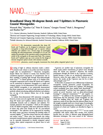
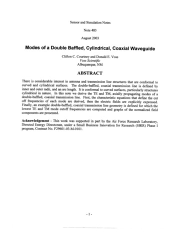
Rectangular to Parallel Plate Waveguide Transition and Its Tapering EffectElectric (TE) wave mode with no electric field component in the propagation direction (Ez 0,Hz 0), and the Transverse Magnetic (TM) wave mode with no magnetic field component inthe propagation direction (Ez 0, Hz 0). It should be noted that the electric and magneticfields are assumed to propagate in z direction.Since the structure is a loss-free PPW, thence it has only imaginary part of propagationconstant (α 0, γ jβ). This condition allows the wave modes to propagate in the PPW whereit operates at frequency higher than its cut-off frequency. The cut-off frequency for TE and TMwave modes is given by (1) [8], [11].TMf cTE,m fc,m c m(1)2d μ r ε rwhere c is the light velocity at free space (3 x 10⁸ ms-1), and m is an integer (1,2,3, ) which isrelated to the number of field variations in y-direction. Figure 2 plots the cut-off frequency ofTE and TM wave modes for the first three values of m in which the distance d is varied from50mm to 100mm. From the figure, it notes that the lowest wave mode is the TE1 or TM1 wavemode, and is normally the one used.Cut-off frequency (GHz)10TE 1, TM 1 wave modeTE 2, TM 2 wave modeTE 3, TM 3 wave mode8642050607080Distance d (mm)90100Figure 2. Cut-off frequency of TE and TM wave modes for first three values of mIn contrast to both cut-off frequencies which are similar each other, wave impedances forthe TE1 and TM1 wave modes are oppositely each other where they are expressed in (2) and (3)for the TE1 and TM1 wave modes, respectively.ZTE1 ZTM 1 k0k02 (π d )2k02 (π d )2k0Z0(2)Z0(3)where k0 is wavenumber which is defined as k0 ω μ0ε 0 and Z0 is the characteristicimpedance of free space, i.e. 120π Ω. Figure 3 depicts the theoretical wave impedance for theTE1 and TM1 wave modes with the distance d of 75mm. It shows that for higher frequencies,the wave impedances for both wave modes are converged approaching the characteristicimpedance of free space.183
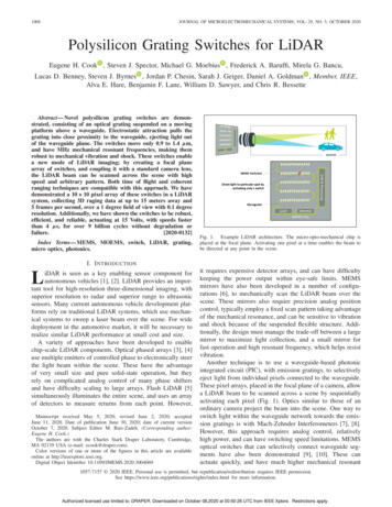
Achmad Munir, et alWave impedance (Ω)600TE 1 wave modeTM 1 wave mode525450375free spaceimpedance3002250369Frequency (GHz)1215Figure 3. Wave impedances for TE1 and TM1 wave modes with distance d of 75mmB. Analysis of Tapered TransitionIn practical implementation, the PPW is usually illuminated using waveguide as a waveexciter. The used waveguide which is usually a rectangular type can be connected to the PPWeither directly or through a transition section. In case of the rectangular waveguide dimension,i.e. the height, is different with the PPW dimension, i.e. the distance between plates, thetransition section is mostly required for adapting both dimensions. In addition, the transitionsection is also applicable for improving impedance matching between the PPW and therectangular waveguide. Some type of transition section frequently used is tapered one as shownin Figure 4.waveguidesectionh1waveguidesectiontransition section(linear-tapered)PPWsectionh2dn-1 dnd1 d2bPPWsectiontransition section(step-tapered)l1ddbl2lsln-1lnlt(a) step-tapered transition section(b) linear-tapered transition sectionFigure 4. Side view of PPW connected with rectangular waveguideusing tapered transition sectionBy considering b is the height of rectangular waveguide, e.g. coaxial-to-waveguidetransducer and d is the distance between two plates of PPW, then both are connected using astep-tapered transition section with the length of ls as shown in Figure 4(a). The transitionsection is divided uniformly into n steps, so that the length (ln) and the height (hn) of each stepare uniform and can be expressed in (4) and (5), respectively.l1 . ln lsn 1(4)184
Rectangular to Parallel Plate Waveguide Transition and Its Tapering Effecth1 . hn d b2(n 1)(5)The distance between plates (di) of i-th step, i.e. i 1, 2, 3,., n-1, can be calculated using(6). Since for each step the distance d has a specific value, this affects to wave impedances.Thus for the TE1 and TM1 wave modes, (2) and (3) should be redefined as written in (7) and(8), respectively.(6)di b 2(i 1)hZTE1 i ZTM 1 i k0k02 (π d i )2k02 (π d i )2k0Z0(7)Z0(8)Wave impedance (Ω)1000n 64n 8n 4800TE1 wave mode600400free space impedance200TM1 wave mode0405060708090Distance between plates for transition section (mm)Figure 5. Wave impedances of step-tapered transition section at frequency of 4GHz for TE1and TM1 wave modesFigure 5 plots wave impedances of step-tapered transition section calculated using (7) and(8) at frequency of 4GHz for the TE1 and TM1 wave modes. The transition section which hasthe length ls of 100mm is divided uniformly into three n steps, i.e. 4 steps, 8 steps, 64 steps, toconnect a rectangular waveguide with the height b of 34mm and a PPW with the distance d of90mm. It is seen that the wave impedances of i-th step are gradually changed following thevalue of d. The larger number of step n the smoother wave impedance obtained. This isusefulness of transition section for minimizing the impedance mismatch between rectangularwaveguide and PPW in addition to the geometry matching between both dimensions. Incontrary, the geometry of linear-tapered transition section as shown in Figure 4(b) is simplerthan the step-tapered transition section. The important parameters in designing the lineartapered transition section are the length (lt), the distance between plate (d), and the height ofrectangular waveguide (b). Actually the linear-tapered transition section is a special geometrycondition of step-tapered transition section, in which the number of step n is large enoughaffecting to the much smaller value of the length (ln) and the height (hn) of each step. This isshown in Figure 5 for number of step n of 64. Therefore, the wave impedances of the liniertapered transition are smoother than of the step-tapered one.185
Achmad Munir, et al3. Characterization and DiscussionA. Numerical CharacterizationA rough sketch of test-fixture for numerical characterization is illustrated in Figure. 6. Itcomprises of a rectangular waveguide and a PPW in which both are connected using transitionsection. The rectangular waveguide of WR248 type with the width a of 72mm and the height bof 34mm which has working frequency of 2.60GHz to 3.95GHz for TE10 wave mode is used ascoaxial-to-waveguide transducer for exciting the PPW. Meanwhile, the PPW has the length l of600mm, distance d of 90mm and the width w of 200mm. In the investigation, 2 types oftransition section, i.e. step-tapered and linear-tapered transition sections, are applied for thecharacterization to obtain the optimum performance in term of reflection coefficient,impedance and working bandwidth. At first, both transition sections are set to have 100mmlength. The number of step n for step-tapered transition section is varied from 4 to 16 stepswhere the length and the height of each step are identical each other.waveguidesectiontransition sectionyxPPW sectionzplatedistanceplatewidthFigure 6. Rough sketch of test-fixture for numerical characterizationAs plotted in Figure 7, the reflection coefficient of test-fixture which uses step-taperedtransition section for small number of step, i.e. 4 steps and 8 steps, is higher than the largenumber of step. This is addressed to the higher impedance mismatch for small number of step;as a result more reflected waves occur. The result complies with the theoretical prediction inprevious section that the smaller number of step produces the larger different of impedance ineach step. From the result it seems that the linear-tapered transition section gives smallerfluctuation of reflection coefficient compared to the step-tapered transition section forfrequency range of 2.6GHz to 3.5GHz. This will be beneficial for stability measurement incharacterizing microwave devices. Furthermore, the impedance in inside of test-fixture atfrequency of 3GHz and the working bandwidth are depicted in Figures 8 and 9, respectively. Itcould be noted that the 4 steps used in step-tapered transition section has larger fluctuation ofimpedance than others. The fluctuation is reduced when the larger number of step, i.e. 8 stepsor 16 steps, or a linear-tapered transition is employed. In despite of having fluctuatedimpedance, its working bandwidth is the widest one, i.e. around 2.15GHz, as shown in Figure9. Here, the working bandwidth is defined as the band of frequency bounded by reflectioncoefficient of -10dB. As the 4 steps of step-tapered transition section has the lowest transmittedpower compared with others indicated by the worst reflection coefficient, due to a trade-offbetween the transmitted power and the bandwidth, therefore the widest working bandwidth isobtained.186
Rectangular to Parallel Plate Waveguide Transition and Its Tapering EffectReflection coefficient (dB)0-10-20-30-404 steps8 steps16 stepslinear-tapered-50234Frequency (GHz)5Figure 7. Reflection coefficient of test-fixture using step-tapered and linear-tapered transitionsectionsImpedance (Ω)600waveguide sectiontransition sectionPPW section500(obtained at 3GHz)400300freespaceimpedance200-1504 steps8 steps16 stepslinear-tapered0150300450Position in inside of test-fixture (mm)600Figure 8. Impedance in inside of test-fixture using step-tapered and linear-taperedtransition sections187
Achmad Munir, et alWorking bandwidth (GHz)2.22.1linear-tapered transition21.91.84681012Number of step1416Figure 9. Working bandwidth of test-fixture using step-tapered and linear-tapered transitionsectionsAs the next investigation, the length of transition section for step-tapered transition isvaried from 50mm to 150mm where the number of step 4 is applied for numericalcharacterization. Figures 10 and 11 plot the reflection coefficient and the impedance for testfixture at frequency of 3GHz which uses step-tapered transition section, respectively. It showsthat the length of transition section of 75mm produces the better reflection coefficientcompared to other lengths for frequency range of 2.6GHz to 3.0GHz. The length of 75mm hasalso the smallest fluctuation of impedance as plotted in Figure 11. However, for higherfrequency range, i.e. 3.0GHz to 3.4GHz, the length of 50mm seems to be better than others interm of reflection coefficient. Therefore, this will be an advantage for improving the accuracyof microwave devices characterization which has frequency response belong that frequencyrange.Reflection coefficient hlengthlength34Frequency (GHz)5Figure 10. Reflection coefficient of test-fixture using step-tapered transition section of 4 stepswith different length of transition section188
Rectangular to Parallel Plate Waveguide Transition and Its Tapering EffectImpedance (Ω)600(obtained at 3GHz)400freespaceimpedance200-15050mm length75mm length100mm length150mm length0150300450Position in inside of test-fixture (mm)600Figure 11. Impedance in inside of test-fixture using step-tapered transition section of 4 stepswith different length of transition sectionReflection coefficient hlengthlength34Frequency (GHz)5Figure 12. Reflection coefficient of test-fixture using linear-tapered transition section withdifferent length of transition sectionIn comparison to the step-tapered transition, the investigation for length variation of lineartapered transition section to the performance of test-fixture is examined. As the previousinvestigation, the length of linear-tapered transition is varied from 50mm to 150mm. Theresults are depicted in Figures 12 and 13 for the reflection coefficient and the impedance ininside of test-fixture at frequency of 3GHz, respectively. It can be noted from Figure 12 thatthe length of linear-tapered transition section of 75mm yields the reflection coefficient which isbetter than other lengths for frequency range of 2.6GHz to 3.0GHz. It can also be seen in theimpedance plotted in Figure 13 where the length of linear-tapered transition section of 75mmhas smallest fluctuation. This is similar as the previous investigation of using step-taperedtransition section of 4 steps. However, for frequency range from 3.0GHz to 3.4GHz, althoughthe impedance has more fluctuated values, the length of 50mm shows better performancecompared to others where this also coincides with the step-tapered transition section of 4 steps.189
Achmad Munir, et alImpedance (Ω)600(obtained at 3GHz)400freespaceimpedance200-15050mm length75mm length100mm length150mm length0150300450Position in inside of test-fixture (mm)600Figure 13. Impedance in inside of test-fixture using linear-tapered transition section withdifferent length of transition sectionHence, it can be inferred that the test-fixture with length of transition sections of 75mm issuitable to be applied for characterizing microwave devices which has working frequencybelow 3GHz. Meanwhile, for the devices with higher frequency response, it can becharacterized using test-fixture with a shorter length of transition section. Furthermore, asshown in Figure 14, the working bandwidth of test-fixture using linear-tapered transition forvaried length of transition section is flatter than of the step-tapered transition section. Theresults indicate that the varied length of linear-tapered transition section gives no significantinfluence for working bandwidth response compared to the step-tapered transition. The widestworking bandwidth is obtained by the test-fixture using linear-tapered transition section withthe length of 150mm, i.e. 2.136GHz, whereas from the step-tapered transition of 4 steps, thewidest one is 2.153GHz which is produced by the length of 100mm.Working bandwidth (GHz)2.521.51step-tapered transition (4 steps)linear-tapered transition0.55075100125Length of transition section (mm)150Figure 14. Working bandwidth comparison of test-fixture with varied length of transitionsection for step-tapered transition section of 4 steps and linear-tapered transition section190
Rectangular to Parallel Plate Waveguide Transition and Its Tapering EffectB. Realization and Experimental CharacterizationBased on the numerical characterization, by considering the ease of fabrication, a testfixture with linear-tapered transition section of 100mm length is realized for experimentalcharacterization. In addition, from the numerical result it has been shown that the lineartapered transition section of 100 length has wide enough of working bandwidth and smallenough of impedance fluctuation. As shown in Figure. 15, the test-fixture is fabricated using a2mm aluminum sheet for top and bottom plates as well as for linear-tapered transition section.Where as a WR248 type rectangular waveguide as coaxial-to-waveguide transducer forexciting the PPW is installed separately. The absorbent materials are placed surrounding thetest-fixture at the outside of 200mm plate width as shown in Figure. 15(b) to avoidinterferences coming from the front end test-fixture to the outside or vice versa. In addition, 4pairs of non-metallic screw are employed at the area of absorbent material to keep the distancebetween plates of 90mm. In practical, the DUT of microwave devices such as FSS arepositioned at the front-end of PPW away from the waveguide entmaterialscrewlinearbottom platetaperedtop plateposition of DUT200mmscrew(a) overall view of test-fixture(b) test-fixture without top plateFigure 15. Picture of fabricated test-fixture with linear-tapered transition sectionReflection coefficient (dB)0-10-20-30-40-502Measured resultSimulated result34Frequency (GHz)5Figure 16. Measured reflection coefficient of test-fixture with linear-tapered transition sectionwith numerical result as comparisonThe experimental characterization result of fabricated test-fixture is depicted in Figure 16where the numerical result is plotted together as comparison. Some discrepancies appear at191
Achmad Munir, et alfrequency range of 2.65GHz to 3GHz and 3.3GHz to 3.75GHz, where the measured reflectioncoefficient is higher than simulated one with the maximum different value about 30dB whichhappened at frequency of 3.6GHz. The differences are also seen in higher frequency range of3.8GHz to 4.8GHz with the maximum value of 20dB at frequency of 4GHz. These happened asthere were some different conditions and assumptions, such as the used material parametersand boundary conditions. It should be noted that the parameters of material and the boundarycondition applied in the numerical characterization are frequency independent and perfectlyabsorbing material, respectively. Nevertheless, from the experimental characterization, it canbe concluded that the characteristic of realized test-fixture with linear-tapered transition sectionof 100mm length has coincided qualitatively with the numerical one; therefore, it is suitable formicrowave device characterization.4. ConclusionThe tapering effect of transition section for connecting a rectangular waveguide and aparallel plate waveguide (PPW) has been investigated related to the design of test-fixture formicrowave devices characterization. In addition to matching the different geometry betweenthe rectangular waveguide and the PPW, it has been shown that the transition section both inform of step-tapered and linear-tapered transition sections can minimize the impedancemismatch between the rectangular waveguide and the PPW. It has been demonstrated that thehigher number of step for test-fixture with step-tapered transition section has minimized thereflection coefficient and increased the stability of impedance in inside of test-fixture.Meanwhile, the length of transition section for test-fixture with linear-tapered transition sectionhas had no significant effect to the working bandwidth achievement where it was contradictivewith step-tapered transition of 4 steps. In addition, in despite of discrepancy in the measuredresult, in general the experimental characterization of realized test-fixture with linear-taperedtransition section has shown a good agreement with the numerical one. This will be beneficialin the development of other instruments for microwave device characterization.AcknowledgementThis work is partially supported by the Ministry of Research and Technology, the Republicof Indonesia, under the Grant of Incentive Research Program 2012 contract number1.26/SEK/IRS/PPK/I/2012. The authors wish to thank Mr. Zenal Aripin, a technician atLaboratory of Radio Telecommunication and Microwave, School of Electrical Engineering andInformatics, Institut Teknologi Bandung, Indonesia for supporting experimentation andlaboratory measurement.References[1] R.C. Hansen, Phased array antennas, 2nd Ed., John Wiley & Sons, 2009.[2] N. Lenin and P.H. Rao, “Evaluation of the reflected phase of a patch using waveguidesimulator for reflectarray design”, Microwave and Optical Technology Letters, vol. 45,no. 6, pp.528-531, Jun. 2005.[3] M. Hajian, J.H. Dickhof, C. Trampuz and L.P. Ligthart, “Design of hollow patchmicrostrip reflectarray and measuring phase of reflection coefficient at Ka-band usingwaveguide simulator,” 4th European Conference on Antennas and Propagation (EuCAP)Proc., pp. 1-5, Barcelona, Spain, Apr. 2010.[4] C.C. Njoku, J.C. Vardaxoglou and W.G. Whittow, “Complementary frequency selectivesurfaces in a waveguide simulator,” 7th European Conference on Antennas andPropagation (EuCAP) Proc., pp. 2420 - 2422, Gothenburg, Sweden, Apr. 2013.[5] R. Shelby, D. Smith and S. Schultz, “Experimental verification of a negative index ofrefraction,” Science, vol. 292, pp. 77–79, Apr. 2001.[6] V. Fusco, A. Munir and O. Malyuskin, “Characterisation of microwave phase conjugatesignal generation using nonlinearly loaded wire FSS,” IET Microwaves, Antennas &Propagation, vol. 3, no. 5, pp. 834-842, Jul. 2009.192
Rectangular to Parallel Plate Waveguide Transition and Its Tapering Effect[7] A. Munir, Sugihartono and M.R. Effendi, “Design of parallel-plate waveguide simulatorfor microwave device characterization,” Jurnal Telekomunikasi ITTelkom, vol. 16, no. 2,pp. 105-110, Dec. 2011.[8] R.E. Collin, Field theory of guided waves, 2nd Ed., New Jersey: IEEE Press, 1991.[9] M.F.Y. Musthofa and A. Munir, “Design of rectangular to circular waveguide converterfor S-band frequency,” 3rd International Conference on Electrical Engineering andInformatics (ICEEI) 2011 Proc., pp. 1423-1427, Bandung, Indonesia, Jul. 2011.[10] A. Munir and M.F.Y. Musthofa, “Rectangular to circular waveguide converter formicrowave devices characterization,” International Journal of Electrical Engineering andInformatics, vol. 3, no. 3, pp. 350-359, Oct. 2011.[11] D.M. Pozar, Microwave engineering, 3rd Ed. John Wiley & Sons, 2005.Achmad Munir received the B.E. degree in Electrical Engineering fromInstitut Teknologi Bandung, Indonesia, in 1995, the M.E. and D.E. degrees inscience and engineering from Yamaguchi University, Japan, in 2002 and2005, respectively. From 2005 to 2007, he was a Research Fellow under JSPSfellowship program with department of Electrical and ElectronicsEngineering, Faculty of Engineering, Yamaguchi University, Japan, workingon the artificial materials research, particularly, artificial dielectric andartificial magnetic materials. From 2007 to 2009, he was a Research Fellowwith the Institute of Electronics, Communications, and Information Technology, QueensUniversity Belfast, Northern Ireland, United Kingdom, involved in the experimental study ofnovel nonlinear artificial material including high impedance surface and artificial magneticconductor for advanced EM applications. In January 2009, he joined the School of ElectricalEngineering and Informatics, Institut Teknologi Bandung, Indonesia, as Lecturer. His researchinterests include linear and nonlinear artificial materials, electromagnetics wave propagation,and microwave devices.Ananto Eka Prasetiadi received the B.E. degree in TelecommunicationEngineering and the M.E. degree in Electrical Engineering(Telecommunication Engineering Option) from School of ElectricalEngineering and Informatics, Institut Teknologi Bandung, Indonesia, in 2010and 2011, respectively. Currently, he is pursuing the doctorate degree at theInstitut für Mikrowellentechnik und Photonik, Technische UniversitätDarmstadt, Germany. His research interests cover antenna, wave propagationand microwave devices characterization.Levy Olivia Nur received the B.E. and M.E. degrees in ElectricalEngineering, majoring in Telecommunication Engineering from InstitutTeknologi Bandung, Indonesia, in 2001 and 2004, respectively. Currently,she is pursuing the doctorate degree at the same university. From 2002 to2003, during her study in master program she joined the Japanese UniversityStudies in Science & Technology (JUSST) at the University of ElectroCommunications (UEC), Tokyo, Japan. From 2006 to 2010, she was aLecturer at Indonesia Computer University (UNIKOM), Bandung, Indonesia.Since 2010, she has been joining the Telkom University
transition related to the performance of test-fixture as well as the experimental characterization for linear-tapered transition are also presented. Keywords: coax-to-waveguide transducer, linear-tapered transition section, microwave devices, parallel plate waveguide, rectangular waveguide, step-tapered transition section. 1. Introduction