Transcription
Dell Latitude E6440Owner's ManualRegulatory Model: P38GRegulatory Type: P38G001
Notes, cautions, and warningsNOTE: A NOTE indicates important information that helps you make better use of your product.CAUTION: A CAUTION indicates either potential damage to hardware or loss of data and tells you how to avoid theproblem.WARNING: A WARNING indicates a potential for property damage, personal injury, or death. 2019 Dell Inc. or its subsidiaries. All rights reserved. Dell, EMC, and other trademarks are trademarks of Dell Inc. or its subsidiaries.Other trademarks may be trademarks of their respective owners.2019 - 04Rev. A01
Contents1 Working on your computer. 5Before working inside your computer. 5Turning Off Your Computer.6After working inside your computer. 62 Disassembly and reassembly.8System Overview. 8Removing the Secure Digital (SD) Card.9Installing the Secure Digital (SD) Card. 9Removing the ExpressCard.9Installing the ExpressCard.10Removing the Battery. 10Installing the Battery. 10Removing the Base Cover.10Installing the Base Cover.11Removing the Memory.11Installing the Memory.11Removing the Hard Drive. 12Installing the Hard Drive. 13Removing the Optical Drive. 13Installing the Optical Drive. 14Removing the Keyboard Trim. 14Installing the Keyboard Trim. 15Removing the Keyboard.15Installing the Keyboard.16Removing the WLAN Card. 16Installing the WLAN Card. 17Removing the WWAN Card. 17Installing the WWAN Card.17Removing the Base Corner Caps. 17Installing the Base-Corner Covers.18Removing the Network Connector.18Installing the Network Connector.19Removing the Coin-Cell Battery.19Installing the Coin-Cell Battery.20Removing the Heatsink Assembly. 20Installing the Heatsink Assembly.21Removing the Processor.21Installing the Processor.22Removing the Power Connector.223
Installing the Power Connector. 23Removing the Display-Hinge Cover. 24Installing the Display-Hinge Cover. 24Removing the Palmrest Assembly. 24Installing the Palmrest Assembly. 26Removing the ExpressCard Cage.26Installing the ExpressCard Cage.27Removing the WiFi-Switch Board.28Installing the WiFi-Switch Board.28Removing the System Board.29Installing the System Board.30Removing the Speakers. 31Installing the Speakers. 32Removing the I/O Board.32Installing the I/O Board.33Removing the Display Assembly.34Installing the Display Assembly.35Removing the Display Bezel. 35Installing the Display Bezel.37Removing the Display Panel. 37Installing the Display Panel. 39Removing the Display Hinges. 39Installing the Display Hinges. 39Removing the Camera.40Installing the Camera.403 System setup.41Boot Sequence. 41Navigation keys. 41System Setup Options.42Updating the BIOS in Windows . 50System and setup password.51Assigning a system setup password.51Deleting or changing an existing system setup password. 514 Diagnostics.53Enhanced Pre-Boot System Assessment — ePSA diagnostics. 53Device status lights.53Battery status lights.545 Technical Specifications.556 Contacting Dell. 604
Working on your computer1Before working inside your computerUse the following safety guidelines to help protect your computer from potential damage and to help to ensure yourpersonal safety. Unless otherwise noted, each procedure included in this document assumes that the followingconditions exist: You have read the safety information that shipped with your computer. A component can be replaced or--if purchased separately--installed by performing the removal procedure in reverseorder.WARNING: Before working inside your computer, read the safety information that shipped with your computer. Foradditional safety best practices information, see the Regulatory Compliance Homepage at www.dell.com/regulatory complianceCAUTION: Many repairs may only be done by a certified service technician. You should only performtroubleshooting and simple repairs as authorized in your product documentation, or as directed by the online ortelephone service and support team. Damage due to servicing that is not authorized by Dell is not covered by yourwarranty. Read and follow the safety instructions that came with the product.CAUTION: To avoid electrostatic discharge, ground yourself by using a wrist grounding strap or by periodicallytouching an unpainted metal surface, such as a connector on the back of the computer.CAUTION: Handle components and cards with care. Do not touch the components or contacts on a card. Hold acard by its edges or by its metal mounting bracket. Hold a component such as a processor by its edges, not by itspins.CAUTION: When you disconnect a cable, pull on its connector or on its pull-tab, not on the cable itself. Somecables have connectors with locking tabs; if you are disconnecting this type of cable, press in on the locking tabsbefore you disconnect the cable. As you pull connectors apart, keep them evenly aligned to avoid bending anyconnector pins. Also, before you connect a cable, ensure that both connectors are correctly oriented and aligned.NOTE: The color of your computer and certain components may appear differently than shown in this document.To avoid damaging your computer, perform the following steps before you begin working inside the computer.1.Ensure that your work surface is flat and clean to prevent the computer cover from being scratched.2.Turn off your computer (see Turning Off Your Computer).3.If the computer is connected to a docking device (docked) such as the optional Media Base or Battery Slice,undock it.CAUTION: To disconnect a network cable, first unplug the cable from your computer and then unplug thecable from the network device.4.Disconnect all network cables from the computer.5.Disconnect your computer and all attached devices from their electrical outlets.6.Close the display and turn the computer upside-down on a flat work surface.NOTE: To avoid damaging the system board, you must remove the main battery before you service thecomputer.7.Remove the main battery.8.Turn the computer top-side up.5
9.Open the display.10. Press the power button to ground the system board.CAUTION: To guard against electrical shock, always unplug your computer from the electrical outlet beforeopening the display.CAUTION: Before touching anything inside your computer, ground yourself by touching an unpainted metalsurface, such as the metal at the back of the computer. While you work, periodically touch an unpaintedmetal surface to dissipate static electricity, which could harm internal components.11. Remove any installed ExpressCards or Smart Cards from the appropriate slots.Turning Off Your ComputerCAUTION: To avoid losing data, save and close all open files and exit all open programs before you turn off yourcomputer.1.Shut down the operating system: In Windows 8:–– Using a touch-enabled device:a.Swipe in from the right edge of the screen, opening the Charms menu and select Settings.b.Select theand then select Shut downUsing a mouse:a.Point to upper-right corner of the screen and click Settings.b.Click theand select Shut down.In Windows 7:1.Click Start.2.Click Shut Down.or2.1.Click Start.2.Click the arrow in the lower-right corner of the Start menu as shown below, and then click Shut Down.Ensure that the computer and all attached devices are turned off. If your computer and attached devices did notautomatically turn off when you shut down your operating system, press and hold the power button for about 4seconds to turn them off.After working inside your computerAfter you complete any replacement procedure, ensure you connect any external devices, cards, and cables beforeturning on your computer.CAUTION: To avoid damage to the computer, use only the battery designed for this particular Dell computer. Do notuse batteries designed for other Dell computers.1.Connect any external devices, such as a port replicator, battery slice, or media base, and replace any cards, suchas an ExpressCard.2.Connect any telephone or network cables to your computer.6
CAUTION: To connect a network cable, first plug the cable into the network device and then plug it into thecomputer.3.Replace the battery.4.Connect your computer and all attached devices to their electrical outlets.5.Turn on your computer.7
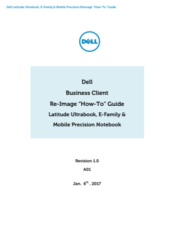
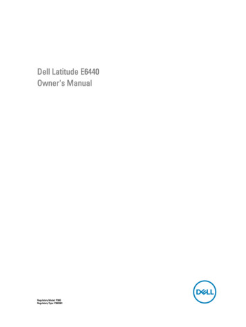
Disassembly and reassemblySystem OverviewFigure 1. Back View — Back Cover Removed1.base corner caps2.power connector3.heatsink assembly4.memory module5.SD card6.ExpressCard slot7.optical drive8.WLAN card9.coin-cell battery10.WWAN card82
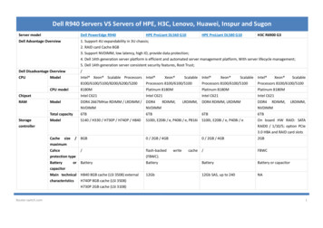
Figure 2. Top View — Keyboard and Palmrest Assembly removed1.WiFi-switch board2.ExpressCard cage3.speakers4.hard-drive bay5.system board6.I/O boardRemoving the Secure Digital (SD) Card1.Follow the procedures in Before Working Inside your computer2.Press in on the SD card to release it from the computer. Slide the SD card out of the computer.Installing the Secure Digital (SD) Card1.Slide the SD card into its slot until it clicks into place.2.Follow the procedures in .After Working Inside Your ComputerRemoving the ExpressCard1.Follow the procedures in Before Working Inside your computer.2.Press in on the ExpressCard to release it from the computer. Slide the ExpressCard out of the computer.9
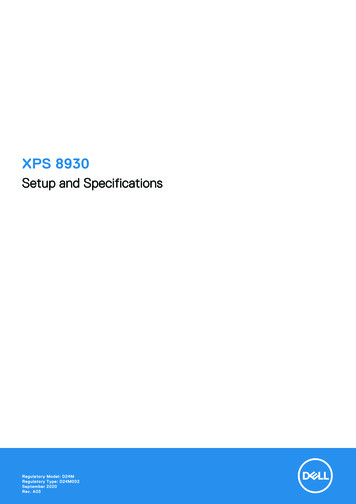
Installing the ExpressCard1.Slide the ExpressCard in its slot until it clicks in place.2.Follow the procedures in After Working Inside Your ComputerRemoving the Battery1.Follow the procedures in Before Working Inside Your Computer.2.Slide the release latches and flip the battery out of the computer.Figure 3. BatteryInstalling the Battery1.Slide the battery into its slot until it clicks into place.2.Follow the procedures in After Working Inside Your Computer.Removing the Base Cover1.Follow the procedures in Before Working Inside Your Computer.2.Remove the screws that secure the base cover to the computer. Lift the base cover and remove it from thecomputer.10
Figure 4. Base coverInstalling the Base Cover1.Place the base cover to align with the screw holes on the computer.2.Tighten the screws to secure the base cover to the computer.3.Install the battery.4.Follow the procedures in After Working Inside Your Computer.Removing the Memory1.Follow the procedures in Before Working Inside your computer.2.Remove:a. batteryb. base cover3.Pry the securing clips away from the memory module until it pops-up and remove the memory module from itsconnector on the system board.Installing the Memory1.Insert the memory into the memory socket.2.Press the securing clips to secure the memory module to the system board.3.Install:a. base coverb. battery4.Follow the procedures in After Working Inside Your Computer.11
Removing the Hard Drive1.Follow the procedures in Before Working Inside your computer.2.Remove the battery.3.Remove the screws that secure the hard drive to the computer. Slide the hard drive out of the computer.4.Remove the screw that secures the hard-drive caddy to the hard drive. Remove the hard-drive caddy from the harddrive.5.Flex the hard-drive isolation. Peel off the hard-drive isolation from the hard drive.12
Installing the Hard Drive1.Fix the hard-drive isolation on the hard drive.2.Attach the hard-drive caddy to the hard drive.3.Tighten the screws to secure the hard-drive caddy to the hard drive.4.Slide the hard drive into the computer.5.Tighten the screws to secure the hard drive to the computer.6.Install the battery.7.Follow the procedures in After Working Inside Your Computer.Removing the Optical Drive1.Follow the procedures in Before Working Inside Your Computer.2.Remove the battery.3.Perform the steps as shown in the illustration:a. Press the optical-drive latch.b. Release the optical drive.c. Pull the optical drive from the computer.4.Remove the screw that secures the optical-drive latch to the optical drive. Slide the optical-drive latch and removeit from the optical-drive.5.Remove the screws that secure the optical-drive latch bracket to the optical drive. Remove the latch bracket fromthe optical drive.13
Installing the Optical Drive1.Align the optical-drive latch bracket to its position on the optical drive.2.Tighten the screw to secure the optical-drive latch bracket to the optical drive.3.Slide the optical-drive latch in the optical-drive latch bracket.4.Tighten the screws to secure the optical-drive latch to the optical-drive latch bracket.5.Slide the optical drive into the drive bay.6.Press the optical-drive latch to secure the optical drive.7.Install the battery.8.Follow the procedures in After Working Inside Your Computer.Removing the Keyboard Trim1.Follow the procedures in Before Working Inside Your Computer.2.Remove battery.3.Using a plastic scribe, pry the keyboard trim to release it from the computer. Lift it up to remove the keyboard trimfrom the computer.14
Installing the Keyboard Trim1.Align the keyboard trim to its slot.2.Press along the sides of the keyboard trim until it clicks in place.3.Install battery.4.Follow the procedures in After Working Inside Your Computer.Removing the Keyboard1.Follow the procedures in Before Working Inside Your Computer.2.Remove the:a. batteryb. keyboard trim3.Remove the screws on the back of the computer and flip the computer.4.Remove the screws that secure the keyboard to the palmrest assembly, lift and flip the keyboard to access thekeyboard-cable.5.Disconnect the keyboard cable from the system board.15
Installing the Keyboard1.Connect the keyboard cable to the system board.2.Slide the keyboard into its compartment until it clicks into place.3.Tighten the screws to secure the keyboard to the palmrest assembly.4.Flip the computer and tighten the screws on the back of the computer.5.Install the keyboard trim.6.Install the battery.7.Follow the procedures in After Working Inside Your Computer.Removing the WLAN Card1.Follow the procedures in Before Working Inside Your Computer.2.Remove:a. batteryb. base cover3.Perform the following steps:a. Disconnect the antenna cables from the WLAN card.b. Remove the screw that secures the WLAN card to the system board.c. Remove the WLAN card from the computer.16
Installing the WLAN Card1.Insert the WLAN card in its connector at a 45–degree angle in its slot.2.Tighten the screw to secure the WLAN card to the computer.3.Connect the antenna cables to their respective connectors marked on the WLAN card.4.Install:a. base coverb. battery5.Follow the procedures in After Working Inside Your Computer.Removing the WWAN Card1.Follow the procedures in Before Working Inside Your Computer.2.Remove:a. batteryb. base cover3.Perform the following steps as shown in the illustration:a. Disconnect the antenna cables from the WWAN card.b. Remove the screw that secures the WWAN card to the computer.c. Remove the WWAN card from the computer.Installing the WWAN Card1.Place the WWAN card in its slot in the system board.2.Press the WWAN card down and tighten the screw to secure the WWAN card to the computer.3.Connect the antenna cables to their connectors on the WWAN card.4.Install:a. base coverb. battery5.Follow the procedures in After Working Inside Your Computer.Removing the Base Corner Caps1.Follow the procedures in Before Working Inside Your Computer.2.Remove the:a. batteryb. base coverc. hard drive3.Remove the screws that secure the left base corner cap, lift and remove it from the computer.17
4.Remove the screw that secures the right base corner cap, lift and remove it from the computer.Installing the Base-Corner Covers1.Place the left and right base-corner covers to align with the screw holes on the computer.2.Tighten the screws to secure the base-corner covers to the computer.3.Install:a. base coverb. battery4.Follow the procedures in After Working Inside Your Computer.Removing the Network Connector1.Follow the procedures in Before Working Inside Your Computer.2.Remove:a. batteryb. base coverc. base corner cap (left)3.Perform the following steps as shown in the illustration:a. Disconnect the cable from the system board [1].b. Release cable from the routing channel [2].c. Remove the screw that secures the network-connector bracket to the computer.18
4.Remove the network-connector bracket from the computer. Lift the network connector from the computer.Installing the Network Connector1.Align the network connector to its position on the computer.2.Place the network-connector bracket on the network connector.3.Tighten the screw to secure the network-connector bracket to the computer.4.Route the cable through the routing channel.5.Connect the cable to the system board.6.Install:a. base-corner cover (left)b. base coverc. battery7.Follow the procedures in After Working Inside Your Computer.Removing the Coin-Cell Battery1.Follow the procedures in Before Working Inside your computer.2.Remove:a. batteryb. base cover3.Disconnect the coin-cell battery cable, pry the coin-cell battery upward, and remove the coin-cell from thecomputer.19
Installing the Coin-Cell Battery1.Place the coin-cell battery in its slot.2.Connect the coin-cell battery cable to the system board.3.Install:a. base coverb. battery4.Follow the procedures in After Working Inside Your Computer.Removing the Heatsink Assembly1.Follow the procedures in Before Working Inside Your Computer.2.Remove:a. batteryb. base cover3.Disconnect the fan cable and remove the screws that secure the heatsink assembly to the system board.NOTE: Remove the screws in the numerical order as displayed in the image.20
4.Perform the following steps as shown in the illustration:a. Lift the heatsink assembly from the computer.b. Slide the heatsink assembly.Installing the Heatsink Assembly1.Place the heatsink assembly to its position on the system board.2.Tighten the screws to secure the heatsink assembly to the system board.3.Connect the fan cable to the system board.4.Install:a. base coverb. battery5.Follow the procedures in After Working Inside Your Computer.Removing the Processor1.Follow the procedures in Before Working Inside your computer.2.Remove:21
a. batteryb. base coverc. heatsink3.Rotate the processor-cam lock in a counter-clockwise direction. Remove the processor from the computer.Installing the Processor1.Align the notches on the processor and the socket, and insert the processor into the socket.2.Rotate the processor-cam lock in a clockwise direction.3.Install:a. heatsinkb. base coverc. battery4.Follow the procedures in After Working Inside Your Computer.Removing the Power Connector1.Follow the procedures in Before Working Inside Your Computer.2.Remove:a. batteryb. base corner cap (right)c. base cover3.22Remove the screw that secures the bracket to the computer and disconnect the camera cable that secures thepower connector to the computer.
4.Unroute the camera and the LVDS cables that secure the power connector to the computer.5.Disconnect the power-connector cable and remove the screw that secures the power connector to the computer.Installing the Power Connector1.Place the power connector in its slot.2.Connect the power-connector cable and tighten the screw that secures the power connector to the computer.3.Route the camera cable and the LVDS cable that secures the power connector to the computer.4.Tighten the screw to secure the power-connector bracket to the computer and connect the camera cable thatsecures the power connector to the computer.5.Install:a. base coverb. base corner cap (right)c. battery6.Follow the procedures in After Working Inside Your Computer.23
Removing the Display-Hinge Cover1.Follow the procedures in Before Working Inside Your Computer.2.Remove the battery.3.Remove the screws that secure the display-hinge cover to the computer and remove it from the computer.Installing the Display-Hinge Cover1.Align the display-hinge cover with the screw holes.2.Tighten the screws to secure the display-hinge cover to the computer.3.Install the battery.4.Follow the procedures in After Working Inside Your Computer.Removing the Palmrest Assembly1.Follow the procedures in Before Working Inside Your Computer.2.Remove:a.b.c.d.e.f.g.h.i.j.3.24SD cardExpressCardbatterykeyboard trimkeyboardhard driveoptical drive
Installing the Hard Drive 1. Fix the hard-drive isolation on the hard drive. 2. Attach the hard-drive caddy to the hard drive. 3. Tighten the screws to secure the hard-drive caddy to the hard drive. 4. Slide the hard drive into the computer. 5. Tighten the screws to secure the hard d