Transcription
HVAC Fundamentalsi
This page intentionally left blank
HVAC FundamentalsSamuel C. SugarmanTHE FAIRMONT PRESS, INC.iii
Library of Congress Cataloging-in-Publication DataSugarman, Samuel C., 1946HVAC fundamentals/Samuel C. Sugarman.p. cm.Includes index.ISBN: 0-88173-489-6 (print) — 0-88173-490-X (electronic)1. Heating—Equipment and supplies. 2. Ventilation—Equipment andsupplies. 3. Air conditioning—Equipment and supplies. I. TitleTH7345.S795 2004697-dc222004056387HVAC fundamentals/Samuel C. Sugarman 2005 by The Fairmont Press, Inc. All rights reserved. No part of thispublication may be reproduced or transmitted in any form or by anymeans, electronic or mechanical, including photocopy, recording, or anyinformation storage and retrieval system, without permission in writingfrom the publisher.Published by The Fairmont Press, Inc.700 Indian TrailLilburn, GA 30047tel: 770-925-9388; fax: d by Marcel Dekker/CRC Press2000 N.W. Corporate Blvd.Boca Raton, FL 33431tel: 800-272-7737http://www.crcpress.comPrinted in the United States of America10 9 8 7 6 5 4 3 2 10-88173-489-6 (The Fairmont Press, Inc.)0-8493-3665-1 (Dekker/CRC Press)While every effort is made to provide dependable information, the publisher, authors,and editors cannot be held responsible for any errors or omissions.iv
Table of ContentsChapter1HVAC Systems . 1Chapter2Heat Flow . 15Chapter3Heating and Ventilating Systems . 25Chapter4Air Conditioning Systems . 47Chapter5Compressors . 73Chapter6Water Chillers . 83Chapter7Fans . 97Chapter8Air Distribution . 115Chapter9Variable Air Volume . 141Chapter10Pumps and Water Distribution . 169Chapter11Control Systems . 195Chapter12Control System Components . 205Chapter13Choosing an HVAC System . 219Chapter14Heat Recovery . 229Chapter15Energy Conservation Opportunities . 241Chapter16Central Plant Water Chiller Optimization . 259Chapter17Fan Drives . 271Chapter18Terminology. 281Chapter19HVAC Timeline . 291Index . 297v
This page intentionally left blank
ForewordHVAC Fundamentals covers the full range of HVAC systems used intoday’s facilities. This is a comprehensive book providing the reader adetailed description of how HVAC systems operate. The HVAC systemsare divided into components and controls for air, water, heating, ventilating and air conditioning to clearly illustrate the way in which eachsystem, subsystem, control or component contributes to providing thedesired indoor environment. The reader will learn why one componentor system may be chosen over another with respect to design, application, energy conservation, indoor air quality and cost. The book alsocovers heat flow fundamentals and the heat flow calculations used inselecting equipment and determining system operating performanceand costs. Fluid flow fundamentals and equations, and fundamentals ofsystem testing and verification of system performance are also coveredin this book. This gives the reader a complete picture of systems fromconception to operation. The chapters are organized in a way that onebuilds upon another and systems, components, design and applicationare revisited as the reader gains knowledge and insight about the workings of HVAC systems.Sam Sugarmanvii
This page intentionally left blank
AcknowledgmentsWriters do not write alone. I would like to acknowledge just a fewof those colleagues, friends and family who shared their support, ideasand guidance for this project. Bill Payne, my acquisitions editor, for hisintellectual support and stimulating ideas. My friend and HVAC contractor Mark Makie, who has discussed HVAC issues with me for 25years. Technical Safety Services, Inc., headquartered in Berkeley, California, gave me an arena for developing concepts and materials and thenthe space for testing and teaching them. My family and loved ones whowatched me stare at my laptop computer for hours on end, for bringingme sustenance, their critiques and then leaving me in relative solitude—almost alone. And the most special thanks to WJ down by the sea, towhom this book is dedicated.ix
HVAC Systems1Chapter 1HVAC Systemshe objectives of HVAC systems are to provide an acceptablelevel of occupancy comfort and process function, to maintain good indoor air quality (IAQ), and to keep system costsand energy requirements to a minimum.THEATING, VENTILATING, ANDAIR CONDITIONING SYSTEMSCommercial heating, ventilating, and air conditioning(HVAC) systems provide the people working inside buildingswith “conditioned air” so that they will have a comfortable andsafe work environment. People respond to their work environment in many ways and many factors affect their health, attitudeand productivity. “Air quality” and the “condition of the air” aretwo very important factors. By “conditioned air” and “good airquality”, we mean that air should be clean and odor-free and thetemperature, humidity, and movement of the air will be withincertain acceptable comfort ranges. ASHRAE, the American Society of Heating, Refrigerating and Air Conditioning Engineers, hasestablished standards which outline indoor comfort conditionsthat are thermally acceptable to 80% or more of a commercialbuilding’s occupants. Generally, these comfort conditions, sometimes called the “comfort zone,” are between 68 F and 75 F forwinter and 73 F to 78 F during the summer. Both these ranges arefor room air at approximately 50% relative humidity and movingat a slow speed (velocity) of 30 feet per minute or less.An HVAC system is simply a group of components workingtogether to move heat to where it is wanted (the conditioned1
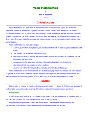
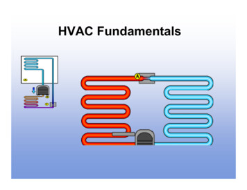
2HVAC Fundamentalsspace), or remove heat from where it is not wanted (the conditioned space), and put it where it is unobjectionable (the outsideair).The components in a typical roof-mounted package HVACsystem (Figure 1-1) are:1. An indoor fan (blower) to circulate the supply and returnair.2. Supply air ductwork in which the air flows from the fan tothe room.3. Air devices such as supply air outlets and return air inlets.4. Return air ductwork in which the air flows back from theroom to the mixed air chamber (plenum).5. A mixed air chamber to receive the return air and mix itwith outside air.6. An outside air device such as a louver, opening or duct toallow for the entrance of outside air into the mixed air plenum.Figure 1-1. Roof-mounted Package Air Conditioning Unit
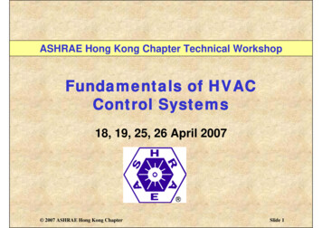
HVAC Systems37. A filter section to remove dirt and dust particles from theair.8. Heat exchangers such as a refrigerant evaporator and condenser coil for cooling, and a furnace for heating.9. A compressor to compress the refrigerant vapor and pumpthe refrigerant around the refrigeration system.10. An outdoor fan (blower) to circulate outside air across thecondenser coil.11. Controls to start, stop or regulate the flow of air, refrigerant,and electricity.HVAC COMPONENTSH is for HeatingBoilers (Figure 1-2) Types of Boilers— Steam— Water Boiler Pressures— Low— High Boiler Fuels— Natural Gas— Oil— Coal— Electricity Boiler Configurations— Fire Tube— Water TubeFurnaces (Figure 1-3) Furnace Fuels— Natural Gas— Oil— Coal— LPG (Liquid Petroleum Gas)— Electricity
4HVAC FundamentalsHeating Coils (Figure 1-4) Types of Heating Coils— Steam— Water— ElectricalV is for Ventilation for each of the following:1) Approximately 20 cfm (cubic feet per minute) of air volumeper person of outside air (OA) for ventilation for non-smoking areas.2)Make-up air (MUA) for exhaust systems such as:— Kitchen hoods— Fume hoods— Toilets3)Room (conditioned space) pressurization— 0.03 to 0.05 inches of water gage for commercial buildings.Figure 1-2. Fire Tube Boiler
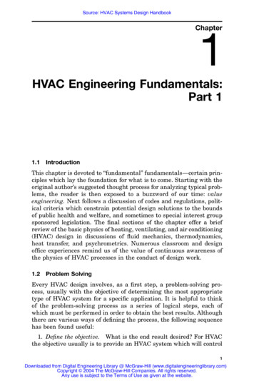
HVAC Systems5Figure 1-3. Natural Gas FurnaceAC is for Air ConditioningFor most of us, air conditioning means comfort cooling witheither chilled water systems or refrigerant systems. Both of thesesystems include cooling coils to remove heat from the air. Chilled Water Systems— Vapor-compression system— Absorption system Refrigeration (DX) Systems— Vapor-compression system Cooling Coils— Water coil— Refrigerant (DX) coil
6HVAC FundamentalsFigure 1-4. Hot Water Heating CoilCooling and heating coils (Figure 1-4) are heat transfer devices or heat exchangers. They come in a variety of types andsizes and are designed for various fluid combinations: water, refrigerant or steam. Water coils are used for heating, cooling ordehumidifying air and are most often made of copper headersand tubes with aluminum or copper fins and galvanized steelframes.
HVAC Systems7AC (Air Conditioning) also meansconditioning the air in the following ways: Temperature (tempering the air)Cooling (removing heat)Heating (adding heat) Humidity control— Dehumidifying (removing moisture)— Humidifying (adding moisture) Volume of airflow— cfm (cubic feet per minute) Velocity (speed) of airflow— fpm (feet per minute) Cleaning— Filtering Pattern of airflow— Direction horizontal verticalCENTRAL HVAC SYSTEM COMPONENTS (Figure 1-5)ComponentsCooling Tower, CTCondenser Water Pump, CWPCondenser Water Supply, CWSCondenser Water Return, CWRCondenser, CondEvaporator (Water Chiller, Water Cooler), EvapCompressor, CompThe condenser, evaporator and compressor together are typically called the Chiller, CH
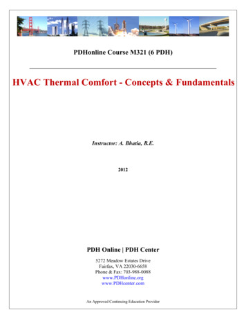
8HVAC FundamentalsFigure 1-5. Air HandlingUnit (AHU)
HVAC Systems9Chilled Water Pump, CHWPChilled Water Supply, CHWSChilled Water Return, CHWRChilled Water Coil (Cooling Coil), CCHeating Water Coil (Hot Water Coil, Heating Coil), HCHeating Water Supply, HWS or HHWSHeating Water Return, HWR or HHWRHeating Water Pump, HWPBoiler, BSupply Air Fan, SAF, SFSupply Air Duct, SAManual Volume Damper, MVDFlex Duct, FlexCeiling Diffuser, CDReturn Air Inlet, RAReturn Air Duct, RAReturn Air Fan, RAFReturn Air Dampers, RA, ATC Damper (Automatic TemperatureControl Damper)Exhaust Air (Dampers), EA, ATCDOutside Air (Dampers) OA, ATCDFilters, FWater Valves, 3-way or 2-way ATC Valve(Automatic TemperatureControl Valve). MBV (Manual Balancing Valve) or Self-regulating Balancing ValveThis AHU is located on the roof and is therefore designatedas a “roof top unit” (RTU).HOW AN HVAC SYSTEM WORKSAn HVAC system is designed to provide conditioned air tothe occupied space, also called the “conditioned” space, to maintain the desired level of comfort. To begin to explain how anHVAC system works let’s set some design conditions. First, we
10HVAC Fundamentalswill need to determine the ventilation requirements. We know thatin the respiratory process the contaminate carbon dioxide is exhaled. In buildings with a large number of people, carbon dioxideand other contaminants such as smoke from cigarettes and odorsfrom machinery must be continuously removed or unhealthy conditions will result. The process of supplying “fresh” air (now mostoften called outside air) to buildings in the proper amount to offsetthe contaminants produced by people and equipment is known as“ventilation”. Not only does the outside air that is introduced intothe conditioned space offset the contaminants in the air but because of its larger ion content, outside air has a “fresh air” smell incontrast to the “stale” or “dead air” smell noticed in overcrowdedrooms that do not have proper ventilation. In many instances, local building codes stipulate the amount of ventilation required forbuildings and work environments.Let’s say that an HVAC system supplies air to a suite in anoffice complex and the code requirement is for 20 cubic feet perminute (abbreviated cfm) of outside air for each building occupant. If the suite is designed for 10 people then the total outsideair requirement for the people in the suite is 200 cfm. An additional amount of outside ventilation air may be required if thereare exhaust hoods such as laboratory fume hoods, kitchen hoods,and spray hoods or there are other areas where the air needs tobe exhausted or vented to the outside such as bathrooms andrestrooms. This ventilation air is called make-up air.If more air is brought into a room (conditioned space) thanis taken out of a room the room becomes positively pressurized.If more air is taken out of a room than is brought into a room theroom becomes negatively pressurized. These air pressures,whether positive or negative are measured in inches of watergage (in wg) or inches of water column (in wc).Commercial office buildings are typically positively pressurized to about 0.03 inches of water pressure. This is done to keepoutside air from “infiltrating” into the conditioned space throughopenings in or around doorways, windows, etc. Other areas thatneed positive pressurization are hospital operating rooms and
HVAC Systems11clean rooms. Examples of negative rooms are commercial kitchens,hospital intensive care units (ICU) and fume hood laboratories.Air VolumeUsing the roof top air handling unit (Figur
HVAC Fundamentals covers the full range of HVAC systems used in today’s facilities. This is a comprehensive book providing the reader a detailed description of how HVAC systems operate. The HVAC systems are divided into components and controls for air, water, heating, venti-lating and air conditioning to clearly illustrate the way in which each system, subsystem, control or component .