Transcription
Selection Guide 0.25 kW – 400 kWVLT AutomationDrive FC 301/30298%Energy efficiencySave energy andmoney with up to98% efficient VLT drives.www.danfoss.com/drives
2VLT AutomationDrive 0.25 kW – 400 kW
This brochurecovers0.25 – 400 kWFor drivesfrom 400 kWto 1.4 MW consultthe VLT HighPower DrivesSelection GuideConsistency.Reliability. Versatility.And all the poweryou need.The VLT AutomationDriveis a globally supporteddrive concept that providesexceptional control of allmotor driven applications.From standard to permanent magnetmotors on any industrial machine orproduction line; regardless of wherea VLT AutomationDrive FC 301/302is installed, it saves expensive energy,increases flexibility and strengthensreliability for its owners.Reduce project costs, ensure the lowestpossible cost of ownership and maintainhigh efficiency processes with a premier,proven and future-ready motor controlsolution.Every VLT AutomationDrive is based on45 years of experience and innovation.Easy to use, all models follow the samebasic design and operating principle.Once you know one, you know them all.This selection guide helps you chooseand configure your perfect drive forapplications from 0.25-400 kW. 0.25 kW – 400 kW VLT AutomationDrive3
Control motors down to0.37 kW without a step-downtransformer on 690 V mains.50 C ambient temperaturewithout deratingGLOBAL REACHDanfoss’ efficient global logistics setup makes it possibleto ship VLT drives quickly to any destination.Danfoss’ global support organization is geared to reactswiftly to resolve issues to help you reduce downtime. Inthe event of issues Danfoss’ global hotline helps you findthe right solution quickly and efficiently.In order to provide fast support in major industrial areasDanfoss is also present with highly trained, dedicatedprofessionals. Based close to chemical hotspots, marinehubs and major industrial areas around the world,Danfoss experts are ready to provide fast access to driveand application expertise.TRAINING BASED ON EXPERIENCEKeep up to date on trends, methods and featuresthat save additional energy or offer new technicalopportunities to increase your product quality or decreasethe downtime of your plant.Receive the same quality training anywhere in the worldwith Danfoss-developed material and trainers. Trainingcan take place at one of Danfoss’ facilities or directly atthe customer’s own facility. Teaching is conducted bylocal trainers who have broad experience in the manyconditions that may affect performance, so you get themost out of your Danfoss solution.Additionally, the online platform Danfoss Learning offersyou the opportunity to extend your knowledge in smalland compact lessons up to extensive training courses,when and wherever you want.Read more at learning.danfoss.com4VLT AutomationDrive 0.25 kW – 400 kW
Flexible, modular and adaptableBuilt to lastA VLT AutomationDrive is built on aflexible, modular design concept toprovide an extraordinarily versatilemotor control solution. The drivesis equipped with a wide rangeof industry features that enableoptimal process control, higherquality output and reduce costsrelated to spare parts and service.Up to 1.4 MWAvailable in a power range from0.25 kW to 1.4 MW the VLT AutomationDrive FC 300 series cancontrol nearly all standard industrialmotor technologies, includingpermanent magnet motors, copperrotor motors and direct line PM.The frequency converter is designed towork with all common supply voltages:200-240 V, 380-480/500 V, 525-600 Vand 525-690 V. This means that systemdesigners, OEMs and end users are freeto connect the drive to their chosenmotor and remain confident that thesystem will perform to the highestpossible standards.690 VThe 690 V versions of VLT AutomationDrive FC 302 units for thepower range from 1.1 kW up to 75 kWcan control motors down to 0.37 kWwithout step-down transformer. Thisenables you to choose from a broadvariety of compact, reliable and efficientdrives for demanding productionfacilities operating from 690 V mainsnetworks.Reduce costs withcompact drivesA compact design and efficient heatmanagement enable the drives to takeup less space in control rooms andpanels, thereby reducing initial costs.Compact dimensions are also anadvantage in applications wheredrive space is restricted. This makesit possible for designers to developsmaller applications without beingforced to compromise on protectionand grid quality. For example,the D frame versions of the VLT AutomationDrive FC 302 from 90400 kW are 25-68% smaller thanequivalent drives.the setup process, which results infewer faults due to configuration andparameterization errors.Especially impressive is the 250 kW,690 V version, which is the smallest inits power class on the market today,and is available in an IP 54 enclosure.Despite the compact dimensions,all units are nevertheless equippedwith integrated DC link chokes andEMC filters, which help to reduce gridpollution and reduce cost and effortsfor external EMC-components andwiring.The IP 20 version is optimized forcabinet mounting and features coveredpower terminals to prevent accidentalcontact. The unit can also be orderedwith optional fuses or circuit breakersin the same package size. Control andpower cables are fed in separately atthe bottom.The frequency converters combinea flexible system architecture, whichallows them to be adapted to specificapplications, with a uniform userinterface across all power classes. Thisallows you to adapt the drive to theexact needs of your specific application.As a result project work and costs aresubsequently reduced. The easy to useinterface reduces training requirements.The integrated SmartStart guidesusers quickly and efficiently throughA3 frameD3h frameVLT PLATFORM HIGHLIGHTS Versatile, flexible, configurableUp to 1.4 MW in common voltagesAsynchronous & PM motor control14 fieldbuses supportedUnique user interfaceGlobally supportedEMC filters integrated as standard 0.25 kW – 400 kW VLT AutomationDrive5
Available in any sizeand all protection classesAll Danfoss VLT frequency converters are designedfor efficient and cost saving cooling.VLT AutomationDrives are availablein a broad range of enclosures sizesand protection ratings from IP 20 toIP 66 to enable easy installation in allenvironments: mounted in panels,switch rooms or as stand-alone units inthe production area.same time it removes heat efficientlywhich helps to prolong product life,increase the overall availability of thesystem and reduce faults related tohigh temperatures.that also allows to conduct the heatinto the outside of the control room.Both methods make it possible toreduce the initial cost of the panel orswitch room.In VLT AutomationDrives there is totalseparation between cooling air andthe internal electronics. It protectselectronics from contaminants. At theFor example, by exhausting heatdirectly outside it is possible to reducethe size of the cooling system in thepanel or switch room. This can beachieved with Danfoss’ panel throughcooling system or the extremelyefficient back channel cooling concept,In daily use the benefits are equallyclear as the energy consumption relatedto cooling can be reduced significantly.This means that designers can reducethe size of the air conditioning system,or even eliminate it entirely.PANEL THROUGH COOLINGAn accessory mounting kit for small andmid -range drives enables heat losses tobe dissipated directly outside the panelroom.BACK CHANNEL COOLINGBy directing air through a rear coolingchannel up to 85-90% of the drive’s heatloss is removed directly outside theinstallation room.NO AIR OVER ELECTRONICSComplete separation between coolingair and the internal electronics ensureefficient cooling.Cost saving heat management6VLT AutomationDrive 0.25 kW – 400 kW
VLT AutomationDrivesare available in all enclosureratings from IP 20 to IP 66.Coated circuit boardsThe VLT AutomationDrive is asstandard conforming to class 3C2(IEC 60721-3-3). If used in especiallyharsh conditions it is possible to order aspecial coating that complies with class3C3.Ruggedized for extraprotectionThe VLT AutomationDrive is availablein a ‘ruggedized’ version, that ensuresthat components remain firmly in placein environments characterized by highdegrees of vibration such as Marine andmobile equipment.RETROFITTING.FAST UPGRADE TO NEWESTTECHNOLOGY PLATFORMAs technologies evolve and newer,smaller and more efficient modelsreplace old drives, it is importantto Danfoss that you can changeand upgrade as easily as possible.Minimize downtime in yourproduction and update yourinstallation in a few minutes withprepared tools from Danfoss.With a Danfoss conversion kit itis easy and fast to prepare yourapplication for the future: Mechanical adaptationElectric adaptationParameter adaptationProfibus adaptation 0.25 kW – 400 kW VLT AutomationDrive7
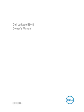
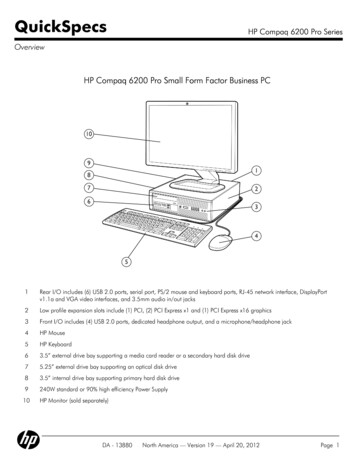
Danfoss VLT AutomationDrivesare equipped with DCchokes that reducemains interferenceto a THDi of 40%.3001500[V]-150-3008162432[ms]HARMONIC DISTORTIONHigh inverter loads without mitigationaffect mains quality.3001500[V]-150-3008162432[ms]OPTIMISED HARMONICPERFORMANCEEfficient harmonic mitigation protectselectronics and increases efficiency.8VLT AutomationDrive 0.25 kW – 400 kW
Optimize performanceand grid protectionBuilt-in protection as standardExpand grid protectionwith filter solutionsThe VLT AutomationDrive FC 300contains all modules necessary forcompliance with EMC standards.If needed, Danfoss’ wide range ofsolutions for harmonic mitigation canprovide additional protection, suchas theA built-in scalable RFI filter minimizeselectromagnetic interference.Integrated DC chokes reduce harmonicdistortion in the mains network, whichincreases the lifetime of the DC linkcapacitors and the drive system’s overallefficiency. VLT Advanced Harmonic Filter AHFVLT Advanced Active Filter AAFVLT Low Harmonic DrivesVLT 12-pulse DrivesThe design of the VLT Automation Drive makes it a perfect choice inapplications that require long motorcables. Without needing additionalcomponents the drive provides troublefree operation with cable lengthsof up to 150 m screened or 300 munscreened. This allows the drive tobe installed in a central control rooma distance away from the applicationwithout affecting motor performance.Provide motor protection with: VLT Sine Wave Filter VLT dU/dt FilterThe solutions save cabinet space, asthey are integrated in the drive fromthe factory. Efficient EMC mitigationalso enables the use of cables withsmaller cross-sections, which againreduces installation costs.With this solutions you may achieveoptimum performance for yourapplication, even in weak or unstablegrids.EMC StandardsConducted emissionEN 55011Facility operators mustcomply with EN 55011Standards andrequirementsUse motor cables up to 300 mEN/IEC 61800-3Converter manufacturersmust conform to EN 61800-3Class BHousingand light industriesClass A Group 1IndustrialenvironmentClass A Group 2Industrial environmentCategory C1Firstenviroment, homeand officeCategory C2Firstenviroment, homeand officeCategory C3SecondenviromentnnnFC 301/302 compliance 1)For further details see the VLT AutomationDrive Design Guide1)Compliance to mentioned EMC classes depends on the selected filter 0.25 kW – 400 kW VLT AutomationDrive9
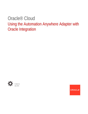
Terminal 37 can be used as “safe coast” for Safe Stop.Safety solutions today span from Safe Torque Off (STO)functionality to extensive safety systems. What is importantis that the chosen solution easily can be integrated inexisting machine concepts.Tailored safetyProtect both equipmentand operatorsVLT Safety Option MCB 140The VLT AutomationDrive FC 302 isdelivered as standard with the STO (SafeTorque Off ) function in compliancewith ISO 13849-1 PL d and SIL 2,according to IEC 61508/IEC 62061.This safety function can be extendedto include SS1, SLS, SMS, SSM, safe jogmode, etc. with the VLT Safety OptionMCB 140 Series and VLT Safety OptionMCB 150 Series.The MCB 140 option is an easy to mountinternal or external safety module.Programming is fast and easy via threebuttons which enables users to set alimited number of parameters whichare handled independently of the drivecontrol algorithm. The module canbe used in high demand applicationsaccording to ISO 13849-1 up to PL e,providing functions such as Safe Stop1 (SS1), Safely Limited Speed (SLS) andSafe Maximum Speed (SMS), controlof external contactors and safety doormonitoring and unlocking.VLT Safety Option MCB 150The VLT Safety Option MCB 150 isintegrated directly in the frequencyconverter and is prepared for futureconnection to common safety bussystems. The module is certifiedaccording to ISO 13849-1 up to PL das well as IEC 61508/IEC 62061 up toFrequencyconverterwithout STO(VLT 5000)OmissibleSafetymodulActuatorContactorsVLT Safety Option MCB 140BeforeFrequencyconverterwith STO(FC 300)AfterTwo contactors can be omitted in safety installations due to the safety functionalityin VLT AutomationDrive.10VLT AutomationDrive 0.25 kW – 400 kW VLT Safety Option MCB 150
Increase flexibility with theVLT Motion Control OptionSIL 2 and provides SS1 and SLS (SMS)functionality. The option can be usedin low and high demand applications.SS1 offers ramp and time basedfunctionality. SLS can be configuredboth with and without ramp down onactivation.Parameter configuration is fullyintegrated into the Danfoss VLT Motion Control Tool MCT 10 frequencyconverter engineering tool and enablessimple start-up and easy maintenance.Key advantages are easy diagnosis andcertification documentation necessaryfor safety acceptance tests, which aresupported by the engineering tool.The VLT Motion Control OptionMCO 305 is an integratedprogrammable motion controllerthat adds additional functionalityand flexibility to the VLT AutomationDrive.In addition the option enables youto implement a variety of applicationfunctions, such as monitoring andintelligent error handling.Dedicated options are preprogrammed for specific tasks:With the Motion Control Option,the VLT AutomationDrive becomesan intelligent drive with highlyaccurate, dynamic motion control,synchronization (electronic shaft),positioning and electronic CAMcontrol.Dedicated options VLT Synchronizing ControllerMCO 350 VLT Positioning ControllerMCO 351 0.25 kW – 400 kW VLT AutomationDrive11
Most popular fieldbuses supportedIncrease productivityWith the wide range of fieldbusoptions the VLT AutomationDrive canbe easily connected to the fieldbussystem of your choice. This makesthe AutomationDrive a future-readysolution that can easily be expandedand updated if your needs change.See the complete list of fieldbuses onpage 34.Danfoss fieldbus options can also beinstalled as a plug-and-play solution ata later stage, if the production layoutdemands a new communicationplatform. This way, you can beconfident that you can optimize yourplant without being forced to replaceyour existing drive system.12VLT AutomationDrive 0.25 kW – 400 kW Download drivers foreasy PLC integrationIntegrating a drive into an existing bussystem can be time consuming andcomplicated. To make this process easyand more efficient, Danfoss providesall necessary fieldbus drivers andinstructions, which can be downloadedfor free from the Danfoss website.After installation the bus parameters,typically only a few, can be set directlyin the VLT drive via the local controlpanel, the VLT MCT 10 or the fieldbusitself.
Software toolsEasy engineering andsetup with VLT MotionControl Tool MCT 10In addition to operating the drive viaLCP (local control panel), VLT drivescan also be configured and monitoredwith Danfoss own PC software. Thisprovides plant managers with acomprehensive overview of the systemat any point in time, adding a newlevel of flexibility in configuration,monitoring and troubleshooting.MCT 10 is a windows based engineeringtool with a clearly structured interfacethat provides an instant overview ofall the drives in a system of any size.The software runs under Windowsand enables data exchange over atraditional RS485 interface, fieldbus(Profibus, Ethernet, etc.) or via USB.existing plant or installation or if youare planning a new installation fromscratch.various additional harmonic reductionmeasures, including Danfoss harmonicfilters.The user-friendly interface allows youto configure the mains environment asdesired and returns simulation results,which you can use to optimize yournetwork.With VLT Motion Control Tool MCT 31,you can determine whether harmonicswill be an issue in your installation, andif so, what strategies will be most costeffective in addressing the problem.Contact your local Danfoss salesoffice or visit our website for moreinformation or visit directly atwww.danfoss-hcs.comVLT Motion Control Tool MCT 31features include: Short circuit current ratings can beused instead of transformer size andimpedance when transformer data isunknown Project oriented for simplifiedcalculations on several transformers Easy to compare different harmonicsolutions within the same project Supports current Danfoss productline as well as legacy drive modelsVLT Motion ControlTool MCT 31 HarmonicsCalculation SoftwareVLT MCT 31 calculates systemharmonic distortion for both Danfossand non-Danfoss drives. It is alsoable to calculate the effects of usingParameter configuration is possibleboth online on a connected drive andoffline in the tool itself. Additionaldocumentation, such as electricaldiagrams or operating manuals, canbe embedded in MCT 10. This reducesthe risk of incorrect configuration whileoffering fast access to troubleshooting.Analyse harmonic distortionwith VLT HarmonicCalculation Software HCSThis is an advanced simulation programthat makes calculating harmonicdistortion in your mains network fastand easy. It is the ideal solution bothif you are planning to extend your 0.25 kW – 400 kW VLT AutomationDrive13
Intuitive setup withgraphical interfaceThe VLT AutomationDrive featuresa user-friendly, hot pluggable localcontrol panel (LCP) for easy setup andparameter configuration.After choosing language navigatethrough setup parameters individually.Alternatively, use a pre-defined quickmenu or a StartSmart guide forapplication specific setup.The LCP can be detached andused to copy settings to otherAutomationDrives in the system. Itcan also be mounted remotely on acontrol panel fascia. This enables theuser to take full advantage of the LCP,eliminating the need for additionalswitches and instrumentation.14VLT AutomationDrive 0.25 kW – 400 kW
Save commissioning timewith SmartStartUsing the graphical control panelSmartStart provides a quick, guideddrive setup procedure that covers themost common applications. By guidingusers through a number of steps, usersavoid the potential confusion whichmay be encountered when accessingthe entire parameter set. By onlypresenting information that is relevant,basic setup is fast and less prone toerror. Conveyor: configuration of horizontalloads in e.g. assembly line, conveyorsand material handling lines. Pump/fan: parameter settingof PID controller Mechanical brake control:configuration of vertical loads such assimple hoists with mechanical brakecontrol. Fieldbus connection: automaticallyallows users to configure the fieldbusconnection when a communicationoption is plugged in the drive andthe application programming isfinished. 0.25 kW – 400 kW VLT AutomationDrive15
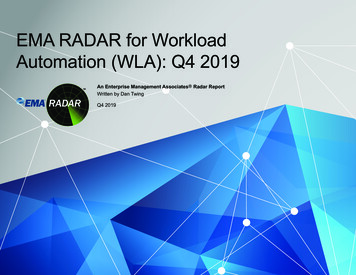
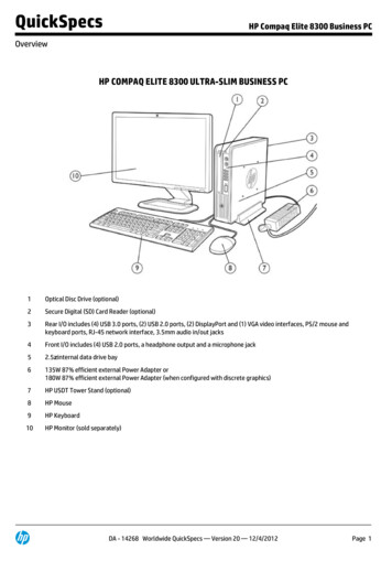
16729835104Modular simplicityDelivered fully assembled and tested to meet your specific requirementsTwo performance levels3. Protective coatingUse the FC 301 version forstandard needs and the FC 302version for applications that needgreater functionality and dynamicresponse.All VLT AutomationDrives conformto class 3C2 (IEC 60721-3-3). If usedin especially harsh conditions it ispossible to order a special coatingthat complies with class 3C3.1. Enclosure4. Removable fanThe drive meets requirements forenclosure class IP 20/Chassis. IP 21/Type 1, IP 54/Type 12, IP 55/Type 12or IP 66/Type 4X.Like most of the elements, thefan can be quickly removed andremounted for easy cleaning.2. EMC and Network effectsDouble-stack, spring-loaded cageclamps enhance reliability andfacilitate easy commissioning andservice.All versions of VLT Automation Drive comply as standard withEMC limits B, A1 or A2 according tothe EN 55011 norm. The standardintegrated DC coils ensure lowharmonic load on the networkaccording to EN 61000-3-12 andincrease the lifetime of the DC linkcapacitors.16VLT AutomationDrive 0.25 kW – 400 kW 5. Control terminals6. Programmable optionsA programmable Motion ControllerMCO 305 adds functionalityand flexibility to the alreadyvery comprehensive standardfunctionality of the drive. Preprogrammed Motion Controllersfor Synchronizing and Positioningare also available, ready for use(MCO 350 and MCO 351).7. Fieldbus optionSee complete list of availablefieldbus options on page 34.8. I/O extensionsA wide range of I/O options areavailable either factory-mounted oras retrofit.9. Display optionDanfoss VLT Drives’ removableLocal Control Panel is available witha variety of language packs: EastEuropean, West European, Asianand North American.
1768953210114English and German are available inall drives.Alternatively the drive can becommissioned via the built-in USB/RS485 connection or a fieldbusfrom with VLT Motion Control ToolMCT 10 setup software.10. 24 V external power supplyThe external 24 V supply keeps theVLT AutomationDrive logic “alive”when the AC mains is removed.11. Mains disconnectThis switch interrupts the mainssupply and has a free useableauxiliary contact.SafetyThe FC 302 is delivered as standardwith the Safe Torque Off (STO)function in compliance with ISO13849-1 Category 3 PL d andSIL 2 according to IEC 61508 lowdemand and high demand mode.The safety functions can beextended to include SS1, SLS, SMS,SSM, safe jog mode etc. with theVLT Safety Option MCB 140 Seriesand VLT Safety Option MCB 150Series.Built-in Smart LogicControlleraction and then starts monitoringfor the next pre-defined event.20 steps of events and resultingactions are available beforereturning to the first set.Logic functions can be selectedand run independent from thesequence control. This enablesdrives to monitor variables or signaldefined events in an easy andflexible way independently of themotor control.The Smart Logic Controller isa clever way to add customerspecific functionality to the driveand increase the opportunities forthe drive, motor and applicationworking together.The controller monitors a specifiedevent. When an event occurs, thecontroller performs a pre-defined 0.25 kW – 400 kW VLT AutomationDrive17
The big pictureAn investment that paysIncrease application performance and streamline processes withenergy efficient, adaptive motor control. Combine reliable, highperforming solutions from a single supplier to reduce the lifetimecosts of your applications.Minimize energy costsReduce total cost of ownershipFor example, by reducing the averagespeed of the motor from 100% to 80%in for example pumps or fans, 50%energy is saved. Reducing the averagespeed by 50% increases the savingsto 80%.During setup Automatic MotorAdaptation (AMA) and later duringoperation Automatic EnergyOptimization (AEO) ensure that thedrive is perfectly adapted to theattached motor and changing loads.Seen over its lifetime, the initial costof a drive only amounts to 10% of thetotal cost of ownership; the remaining90% cover energy consumption,service and maintenance.As energy becomes increasinglyexpensive, variable speed controlof electrical motors has proven tobe one of the most effective costreducing measures available.CostOnce in operation VLT drives servereliably for their entire lifetime. Onlyrequiring minimal maintenance, theVLT AutomationDrives provide a fastreturn on investment and ultimately acompetitive cost of ownership.Automatic EnergyOptimization ensures thatthe motor voltage adaptsautomatically to changingloads. This provides anefficiency boost of up to5-15%, reducing the cost ofownership substantially.Disposal costsInitial costEnergy costOperation andmaintenance costsTimeOn the following pages wehelp you select the optimalVLT for applications from0.25 and 400 kW. For largerdrives, please consult theselection guide for DanfossVLT High Power Drives.18VLT AutomationDrive 0.25 kW – 400 kW
0.25 kW – 400 kW VLT AutomationDrive19
Chose the adequateperformance levelSpecial needs require special features and performancePower range [kW] 200 – 240 VPower range [kW] 380 – (480) 500 VPower range [kW] 525 – 600 VPower range [kW] 525 – 690 VIP 20/21 (Type 1)IP 54/IP 55 (Type 12)IP 66/Type 4xAmbient temperature C w/o de-ratingVVC vector controlU/fFlux vector controlCable length – screened/unscreenedPermanent magnet motor operation (w/wo feedback)KTY-monitoring of temperatureMonitoring of over-voltageSmart Logic ControlSafety function Safe Torque Off (STO – EN 61800-5-2)Galvanic isolation PELVConformal coated PCBs (IEC 60721-3-3), 3C2Removable fanRS 485 and USB-interfaceModbus RTUFC ProtocolGraphical/numerical control panel (LCP 102/101)Scan interval/response time msOutput frequency (OL)Max load (24 V DC) for analogue output and Control card [mA]Pluggable control terminalsAnalogue input (changeable)Analogue output resolutionProgrammable digital inputProgrammable digital output changeableProgrammable Relay OutputProcess PID controlFlying start – catch spinning motorAutomatic Energy Optimization (AEO)Precise Start/StopNumber of fixed parameter setsDigital motor potentiometerIntegrated motor databaseKinetic back-up* For frequency up to 1000 Hz please contact your local Danfoss partner.20VLT AutomationDrive 0.25 kW – 400 kW FC 301 (A1-frame)0.25 – 1.50.37 – 1.5––FC 3010.25 – 370.37 – 75 (480 V )––FC 3020.25 – 370.37 – 1000 (500 V)0.75 – 751.1 – 1200nnn––50 Cnnnn50 Cup to 50 Cnnnnnn–25/50 m––50/75 m–n150/300 nnnnnnnnnnOption50.2 to 590 Hz130Option50.2 to 590 Hz130Option10 to 590 Hz*200nnn0 . 10 V / 4.20 mA12 bit5 (4)110 . 10 V / 4.20 mA12 bit5 (4)110 . 10 V / 4.20 mA12 bit6 (4)22nnnnnnnnnnnn444nnnnnnnnn
SpecificationsBasic unit without extensionsMain supply (L1, L2, L3)Supply voltageSupply frequencyDisplacement power factor(cos ф)Harmonic disturbanceOutput data (U, V, W)Output voltageOutput frequencySwitching on outputRamp timesDigital inputsProgrammable digital inputsChangeable to digital outputLogicVoltage levelMaximum voltage on inputInput resistance, RiScan intervalAnalogue inputsAnalogue inputsModesVoltage levelCurrent levelAccuracy of analogue inputsPulse/encoder inputsProgrammablepulse/encoder inputsVoltage levelPulse input accuracy(0.1 - 1 kHz)Encoder input accuracy(1 – 110 kHz)Digital outputProgrammabledigital/pulse outputsVoltage level atdigital/frequency outputMax. output current(sink or source)Maximum output frequency atfrequency outputAccuracy on frequency outputFC 301FC 302200 – 240 V 10%380 – 480 V 10% 380 – 500 V 10%525 – 600 V 10%525 – 690 V 10%50/60 Hz /- 5% 0.98 near unityMeets EN 61000-3-12FC 301FC 3020 – 100% of supply voltage0.2-590 Hz0-590 HzUnlimited0.01-3600 sec.FC 301FC 3024 (5) 1)4 (6) 1)1 (terminal 27)2 (terminal 27, 29)PNP or NPN0 – 24 V DC28 V DCApprox. 4 kΩ5 ms1 msFC 301FC 3022Voltage or current0 to 10 V-10 to 10 V(scaleable)(scaleable)0/4 to 20 mA (scaleable)Max. error: 0.5% of full scaleFC 301FC 3022/10 – 24 V DC (PNP positive logic)Max. error: 0.1% of full scaleMax. error: 0.05% of full scaleenter 32 (A), 33 (B) and 18 (Z)FC 301FC 302120 – 24 V DCAnalogue outputProgrammableanalogue outputsCurrent range atanalogue outputMax. load to common at analogue output (clamp 30)Accuracy on analogue outputFC 301Control cardUSB interfaceUSB plugRS485 interfaceModbus RTUMax. load (10 V)Max. load (24 V)FC 301FC 3021.1 (Full Speed)Type “B”Up to 115 kBaudSurroundings/externalEnclosureVibration testMax. relative humidityAggressive environment(IEC 60721-3-3)Ambient temperatureGalvanic isolation of all10/4 – 20 mA500 ΩMax. error: 1% of full scale15 mARelay outputProgrammable relay outputsMax. terminal load (AC)on 1-3 (break), 1-2 (make),4-6 (break) power cardMax. terminal load (AC) on 4-5(make) power cardMin. terminal load on1-3 (break), 1-2 (make),4-6 (break), 4-5 (make)power cardFC 302130 mA200 mAFC 3011FC 3022240 V AC, 2 A400 V AC, 2 A24 V DC 10 mA, 24 V AC 20 mAFC 301FC 302IP 00, IP 20, IP 21, IP 54, IP 55, IP 661.0 g (D-enclosure: 0.7 g)5% – 95% (IEC 60721-3-3; Class 3C3(non-condensing) during operationStandard coated PCB Class 3C2,optional coated class 3C3Max. 50 C without derating (highertemperatures possible with derating)I/O supplies according to PELVProtection mode for longest possible up-timeElectronic thermal motor protection against overloadTemperature monitoring of the heat sink ensures that the FC 300 cuts outif the temperature reaches 100 CThe FC 300 is protected against short-circuits and earth fault onmotor terminals U, V, WProtection against mains phase loss1) Terminals 27 and 29 can also be programmed as output.40 mA0 to 32 kHzMax. error: 0.1% of full scaleGlobal Marine 0.25 kW – 400 kW VLT AutomationDrive21
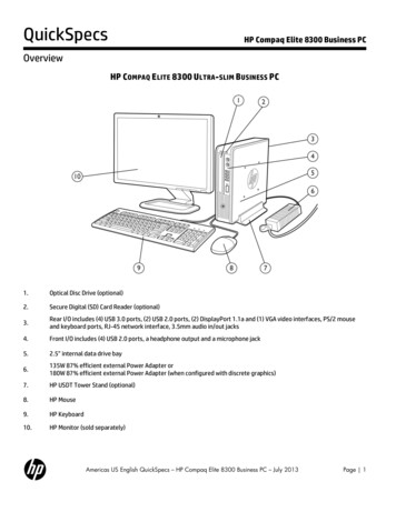
Connection examples3 PhasepowerinputDC bus 10VdcSwitch ModePower Supply24Vdc10Vdc15mA 130/200mA88 (-)89 ( )50 ( 10 V OUT) - ON53 (A IN)S202ON54 (A IN)-relay1ON 0/4-20mAOFF 0/-10Vdc 10Vdc03* relay224V (NPN)0V (PNP)0419 (D IN)24V (NPN)0V (PNP)(COM A OUT) 39(D IN/OUT)24V (NPN)0V (PNP)ON24VS8011 224VAnalog Output0/4-20 mAON TerminatedOFF Open5V24V (NPN)0V (PNP)S8010V32 (D IN)24V (NPN)0V (PNP)33 (D IN)24V (NPN)0V (PNP)*37 (D IN)The diagram shows the terminals of the FC 301 and FC 302.Additional options will expand the number of terminals.Brake chopper (terminals 81 and 82) and load sharing(terminals 88 and 89) must be specified when configuring/ordering.All FC 301/302 have an RS485, a
Selection Guide 0.25 kW – 400 kW VLT AutomationDrive FC 301/302 98% Energy efficiency Save energy and . Receive the same quality training anywhere in the world with Danfoss-developed material and trainers. Training . The design of the VLT Automation-Drive makes it a perfect