Transcription
www.PDHcenter.comPDH Course M197www.PDHonline.orgFundamentals of HVAC ControlsCourse ContentFundamentals of HVAC ControlsThe application of Heating, Ventilating, and Air-Conditioning (HVAC) controls starts with anunderstanding of the building and the use of the spaces to be conditioned and controlled. All controlsystems operate in accordance with few basic principles but before we discuss these, let’s addressfew fundamentals of the HVAC system first.Why Automatic Controls?The capacity of the HVAC system is typically designed for the extreme conditions. Most operation ispart load/off design as variables such as solar loads, occupancy, ambient temperatures, equipment &lighting loads etc keep on changing through out the day. Deviation from design shall result in drasticswings or imbalance since design capacity is greater than the actual load in most operating scenarios.Without control system, the system will become unstable and HVAC would overheat or overcoolspaces.HVAC systemsHVAC systems are classified as either self-contained unit packages or as central systems. Unitpackage describes a single unit that converts a primary energy source (electricity or gas) andprovides final heating and cooling to the space to be conditioned. Examples of self-contained unitpackages are rooftop HVAC systems, air conditioning units for rooms, and air-to-air heat pumps.With central systems, the primary conversion from fuel such as gas or electricity takes place in acentral location, with some form of thermal energy distributed throughout the building or facility.Central systems are a combination of central supply subsystem and multiple end use subsystems.There are many variations of combined central supply and end use zone systems. The mostfrequently used combination is central hot and chilled water distributed to multiple fan systems. Thefan systems use water-to-air heat exchangers called coils to provide hot and/or cold air for thecontrolled spaces. End-use subsystems can be fan systems or terminal units. If the end usesubsystems are fan systems, they can be single or multiple zone type. The multiple end use zonesystems are mixing boxes, usually called VAV boxes.Another combination central supply and end use zone system is a central chiller and boiler for theconversion of primary energy, as well as a central fan system to delivery hot and/or cold air. Thetypical uses of central systems are in larger, multistoried buildings where access to outside air is morerestricted. Typically central systems have lower operating costs but have a complex control sequence.Page 1 of 67
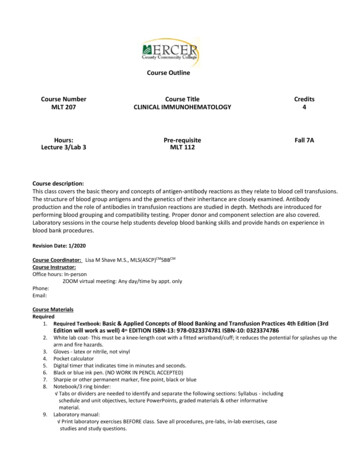
www.PDHcenter.comPDH Course M197www.PDHonline.orgHow does central air-conditioning system work?Cooling Cycle (chilled water system): The supply air, which is approximately 20 F cooler than theair in the conditioned space, leaves the cooling coil through the supply air fan, down to the ductworkand into the conditioned space. The cool supply air picks up heat in the conditioned space and thewarmer air makes its way into the return air duct back to the air handling unit. The return air mixeswith outside air in a mixing chamber and goes through the filters and cooling coil. The mixed air givesup its heat into the chilled water tubes in the cooling coil, which has fins attached to the tubes tofacilitate heat transfer. The cooled supply air leaves the cooling coil and the air cycle repeats.The chilled water circulating through the cooling coil tubes, after picking up heat from the mixed air,leaves the cooling coil and goes through the chilled water return (CHWR) pipe to the chiller'sevaporator. Here it gives up the heat into the refrigeration system. The newly "chilled" water leavesthe evaporator and is pumped through the chilled water supply (CHWS) piping into the cooling coilcontinuously and the water cycle repeats.The evaporator is a heat exchanger that allows heat from the CHWR to flow by conduction into therefrigerant tubes. The liquid refrigerant in the tubes "boils off" to a vapor removing heat from the waterand conveying the heat to the compressor and then to the condenser. The heat from the condenser isconveyed to the cooling tower by the condenser water. Finally, outside air is drawn across the coolingtower, removing the heat from the water through the process of evaporation.The figure below provides a conceptual view of chilled water air-conditioning system with watercooled condenser.The main equipment used in the chilled water system is a chiller package that includes1) A refrigeration compressor (reciprocating, scroll, screw or centrifugal type),2) Shell and tube heat exchanger (evaporator) for chilled water production3) Shell and tube heat exchanger (condenser) for heat rejection in water cooled configuration(alternatively, air cooled condenser can be used, where water is scarce or its use is prohibited)4) A cooling tower to reject the heat of condenser water5) An expansion valve between condenser and the evaporatorThe chilled water system is also called central air conditioning system. This is because the chilledwater system can be networked to have multiple cooling coils distributed through out a large ordistributed buildings with the refrigeration equipment (chiller) placed at one base central location.Page 2 of 67
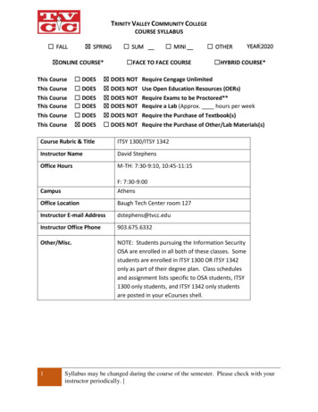
www.PDHcenter.comPDH Course M197www.PDHonline.orgThe heating cycle also follows the same cycle with a difference that the chilled water is replaced withhot water/steam and the chiller is replaced with boiler. The condenser and cooling tower circuit is notneeded.What Parameters are controlled?A proper environment is described with four variables: temperature, humidity, pressure andventilation.TemperatureASHRAE 55-1992 suggests the following temperature ranges for overall thermal comfort.While no single environment can be judged satisfactory by everybody, it varies between people,regions and countries. Uniformity of temperature is important to comfort. The temperatures should notvary within single zone or change suddenly or drastically.HumidityHumidity is the presence of water vapor in air and it affects human comfort. ASHRAE 55-1992recommends the relative humidity (RH) to be maintained between 25 and 60%. Usually air ishumidified to between 25 -45% during winter and dehumidified to below 60% during summer. Anyfigure outside this range shall produce discomfort and indoor air quality (IAQ) problems.VentilationASHRAE Standard 62-1999: “Ventilation for Acceptable Indoor Air Quality” recommends minimumventilation rates per person in the occupied spaces. In many situations, local building codes stipulatethe amount of ventilation required for commercial buildings and work environments. Therecommended value of outside air is typically 20 CFM for each occupant.The ventilation rates specified by ASHRAE effectively dilutes the carbon dioxide and othercontaminants created by respiration and other activities; it supplies adequate oxygen to theoccupants; and it removes contaminants from the space. The ventilation rates greater thanrecommended by ASHARE criteria are sometime required controlling odours and where cooling is notprovided to offset heat gains.PressureAir moves from areas of higher pressure to areas of lower pressure through any available openings. Asmall crack or hole can admit significant amounts of air, if the pressure differentials are high enough(which may be very difficult to assess). The rooms and buildings typically have a slightly positivepressure to reduce outside air infiltration. This helps in keeping the building clean. Typically the stablePage 3 of 67
www.PDHcenter.comPDH Course M197www.PDHonline.orgpositive pressure of .01-.05” is recommended. Pressure is an issue that comes in to play in buildingswhere air quality is strictly watched for example hospitals.Special Control RequirementsThe special requirements pertain to the interlocking with fire protection systems, smoke removalsystems, clean air systems, hazardous or noxious effluent control etc.Control StrategiesThe simplest control in HVAC system is cycling or on/off control to meet part load conditions. Ifbuilding only needs half the energy that the system is designed to deliver, the system runs for aboutten minutes, turns off for ten minutes, and then cycles on again. As the building load increases, thesystem runs longer and its off period is shorter.One problem faced by this type of control is short-cycling which keeps the system operating at theinefficient condition and wears the component quickly. A furnace or air-conditioner takes severalminutes before reaching "steady-state" performance. "Well," you say, "why not just lengthen the timebetween starts to avoid short-cycling?" This is possible but at a cost of some discomfort for short time.The longer the time between cycles, the wider the temperature swings in the space. Trying to find acompromise that allows adequate comfort without excessive wear on the equipment is modulation orproportional control. Under this concept, if a building is calling for half the rated capacity of the chiller,the chilled water is supplied at half the rate or in case of heating furnace; fuel is fed to the furnace athalf the design rate: the energy delivery is proportional to the energy demand. While this system isbetter than cycling, it also has its problems. Equipment has a limited turn-down ratio. A furnace with a5:1 turn-down ratio can only be operated above 20% of rated capacity. If the building demand is lowerthan that, cycling would still have to be used.An alternate method of control under part-load conditions is staging. Several small units (e.g., fourunits at 25% each) are installed instead of one large unit. When conditions call for half the designcapacity, only two units operate. At 60% load, two units are base-loaded (run continuously), and athird unit swings (is either cycled or modulated) as needed. To prevent excessive wear, sequencing isoften used to periodically change the unit being cycled. To continue our example at 60% load:assume Units 1 and 2 are base-loaded, and Unit 3 has just cycled on. When the cycling portion of theload is satisfied, Unit 1 cycle off, and Units 2 and 3 become base loaded. When more capacity isneeded, Unit 4 cycles on, and so on.Where are HVAC controls required?The HVAC control system is typically distributed across three areas:1) The HVAC equipment and their controls located in the main mechanical room. Equipmentincludes chillers, boiler, hot water generator, heat exchangers, pumps etc.2) The weather maker or the “Air Handling Units (AHUs)” may heat, cool, humidify, dehumidify,ventilate, or filter the air and then distribute that air to a section of the building. AHUs are availablein various configurations and can be placed in a dedicated room called secondary equipmentroom or may be located in an open area such as roof top air-handling units.Page 4 of 67
www.PDHcenter.comPDH Course M197www.PDHonline.org3) The individual room controls depending on the HVAC system design. The equipment includes fancoil units, variable air volume systems, terminal reheat, unit ventilators, exhausters, zonetemperature/humidistat devices etc.Benefits of a Control SystemControls are required for one or more of the following reasons:1) Maintain thermal comfort conditions2) Maintain optimum indoor air quality3) Reduce energy use4) Safe plant operation5) To reduce manpower costs6) Identify maintenance problems7) Efficient plant operation to match the load8) Monitoring system performancePage 5 of 67
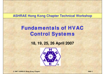
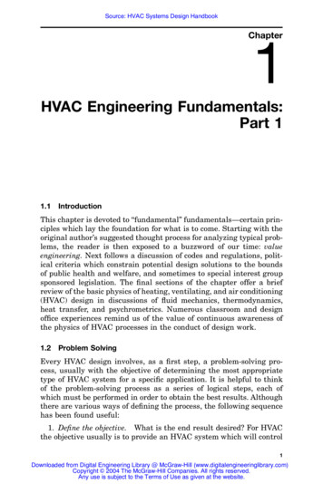
www.PDHcenter.comPDH Course M197www.PDHonline.orgControl BasicsWhat is Control?In simplest term, the control is defined as the starting, stopping or regulation of heating, ventilating,and air conditioning system. Controlling an HVAC system involves three distinct steps:1) Measure a variable and collect data2) Process the data with other information3) Cause a control actionThe above three functions are met through sensor, controller and the controlled device.Elements of a Control SystemHVAC control system, from the simplest room thermostat to the most complicated computerizedcontrol, has four basic elements: sensor, controller, controlled device and source of energy.1) Sensor measures actual value of controlled variable such as temperature, humidity or flow andprovides information to the controller.2) Controller receives input from sensor, processes the input and then produces intelligent outputsignal for controlled device.3) Controlled device acts to modify controlled variable as directed by controller.4) Source of energy is needed to power the control system. Control systems use either a pneumaticor electric power supply.Figure below illustrates a basic control loop for room heating. In this example the thermostatassembly contains both the sensor and the controller. The purpose of this control loop is to maintainthe controlled variable (room air temperature) to some desired value, called a setpoint. Heat energynecessary to accomplish the heating is provided by the radiator and the controlled device is the 2-waymotorized or solenoid valve, which controls the flow of hot water to the radiator.Theory of ControlsBasically there are two types of controls viz. open loop control and closed loop control.Open loop controlOpen loop control is a system with no feedback i.e. there is no way to monitor if the control system isworking effectively. Open loop control is also called feed forward control.Page 6 of 67
www.PDHcenter.comPDH Course M197www.PDHonline.orgIn open loop control the controller may operate an actuator or switch and is often done by a timer andis best explained by the following example of a cooking oven. If the required temperature inside theoven is achieved by switching on and off a heating element, this is known as sequence or open loopcontrol. A timer is set by the operator which operates the electrical circuit to the electric heatingelement. Once the oven reaches the desired temperature, the timer will “close” the
Fundamentals of HVAC Controls The application of Heating, Ventilating, and Air-Conditioning (HVAC) controls starts with an understanding of the building and the use of the spaces to be conditioned and controlled. All control systems operate in accordance with few basic principles but before we discuss these, let’s address few fundamentals of the HVAC system first. Why Automatic Controls? The .