Transcription
Instruction Manual – GRBL CNC Controller1INSTRUCTION MANUAL – GRBL CNC CONTROLLER1Version: 1.2J Tech Photonics, Inc. www.jtechphotonics.comJune 25th, 2018V1.2 Copyright 2018
Instruction Manual – GRBL CNC Controller2CONTENTSInstruction Manual – GRBL CNC Controller .1General .3Overview .3Specifications .3Safety.4Disclaimer .4Connections .4GRBL 1.1 Pinouts .4Setup With Kit Purchase .6Mode Select Jumpers .7Wiring limit switches .7Setting Motor Current Limit .9GRBL Configuration .10DimenSions .112J Tech Photonics, Inc. www.jtechphotonics.comJune 25th, 2018V1.2 Copyright 2018
General3GENERALOVERVIEWThis breakout board is designed to work with the popular GRBL open source firmware for controlling CNC and lasermachines. We have been very involved in the evolution of GRBL and this shield/breakout board is a simple andeffective way to control a machine with GRBL. It offers easy to connect pinout for all signals and JST connectors forthe more well used signals.The board has these features: 4 Standard stepper board pinout carriers.Ability to select clone axis for multiple motor use.Noise suppression limit switch connections.Screw terminal and JST connectors for easy hookup.Reset select for either GRBL reset or Arduino Reset.Works with GRBL 1.1f and Laser ModeThe board has 4 slots for stepper drivers. It comes included with DRV8825 stepper drivers using the TexasInstruments DRV8825 motor driver chip.Stepper Driver Features: 45 V maximum supply voltageSix different step resolutions: full-step, half-step, 1/4-step, 1/8-step, 1/16-step, and 1/32-stepAdjustable current limit setting with potentiometerOver-temperature thermal shutdown, over-current shutdown, and under-voltage lockoutShort-to-ground and shorted-load protectionSPECIFICATIONSSpecificationMinimum Operating Voltage8.2VMaximum Operating Voltage45VContinuous Current Per Phase1.5 ampsMaximum Current Per Phase2.2 ampsCurrent Limit AdjustmentMicrostep ResolutionsConnectors:Operating Temperature:Analog Trim PotFull, 1/2, 1/4, 1/8, 1/16, and 1/32Screw Terminal and JST PH Connectors0 to 40 CStorage Temperature:-40 to 70 CDimensions:3.25” x 2.25”3J Tech Photonics, Inc. www.jtechphotonics.comJune 25th, 2018V1.2 Copyright 2018
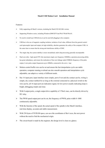
Connections4SAFETY Operate the GRBL Shield - Breakout Board in an explosion free area.The GRBL Shield - Breakout Board may reach high temperatures under operation. Make sure there isadequate airflow to the Driver Board. Also, make sure there is adequate protection around the DriverBoard and that it is not in contact with other materials.DISCLAIMER The GRBL Shield - Breakout Board is designed as an OEM product to be integrated into a final solution.All statements of safety are only applied when the driver board is used in its intended purpose.You are legally responsible for any injury to anybody resulting from the use of or assembly of the GRBLShield - Breakout Board or their finished products.You Accept this driver board as a COMPONENT for integration in a system of YOUR OWN design and willbe legally responsible from any and all LIABILITIES.CONNECTIONSGRBL 1.1 PINOUTSGRBL 1.1 has all of the following outputprovided for operating the CNC machine orLaser machine. All of these signals arerouted through the GRBL shield to theproper places for the stepper drivers andoutput connectors.The GRBL Shield goes on top of the ArduinoUno. It is designed to work with GRBL 0.9 to1.1f. Full kits came pre-installed withversion 1.1f on them.You can see the outputs on the GRBL boardin the following diagram.4J Tech Photonics, Inc. www.jtechphotonics.comJune 25th, 2018V1.2 Copyright 2018
Connections Motor Connections: These are standard 4 pin Dupont Connectors that typical stepper motors come with.Reset: There is a screw terminal connection for an external reset switch as well as a red button on theboard. Both do the same thing. Select using the Reset jumper select to either reset the Arduino(recommended) or just reset GRBL.Step and Direction Clone jumpers: These set the A Motor to follow either X, Y, or Z for step and direction.Make sure both Step and Direction are THE SAME axis you clone. For example, make both Y to clone the Yaxis.Limit Switches: Connect them according to the section “wiring limit switches”.J Tech Photonics, Inc. www.jtechphotonics.comJune 25th, 2018V1.2 Copyright 201855
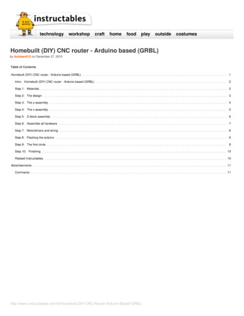
Connections6SETUP WITH KIT PURCHASEIf you bought J Tech stepper motors or a full machine kit, then your machine will be set up correctly with all of theswitches, driver current, and settings out of the box. You will just need to connect the motor cables to the correctmotor axis on the control board.Connecting the motors in this way will make the zero position of your machine be in the front left corner of yourmachine.6J Tech Photonics, Inc. www.jtechphotonics.comJune 25th, 2018V1.2 Copyright 2018
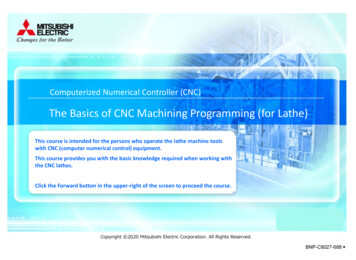
Connections7MODE SELECT JUMPERSThe GRBL Shield – Breakout Board will have jumpers for the stepping mode for the stepper drivers. Use thefollowing table to configure based on your machine requirements.WIRING LIMIT SWITCHESThe limit switches are used to detect the physical limits of the working area and to position the head in initialposition during the homing process. Properly connected limit switches can significantly increase the reliability ofthe GRBL - the microcontroller pins connected to the switches are very vulnerable to any noise.Before starting, make sure your coordinate frame is setup properly on your CNC machine and satisfies the righthand rule. If you're not sure, its explained in the quick setup guide here. Otherwise, you will likely encounterproblems with the homing cycle, where it behaves strangely. If you are having issues with the homing cycle, readthis FAQ.There are two types of end switches wiring: Normally Opened end switches (NO) - switches are connected in parallel, if the head hits one of theswitches the resistance becomes low ( 10 Ohm). The wiring is simple but there is no indication if one ofthe switches is disconnected (broken wire). Normally Closed end switches (NC) - switches are connected in serial, if the head hits one of the switchesthe resistance become high ( 1 MOhm). The wiring is more complicated but if any of the switches isdisconnected (broken wire) this will be immediately detected. This is the way how all professional CNCmachines end switches were wired.J Tech Photonics, Inc. www.jtechphotonics.comJune 25th, 2018V1.2 Copyright 20187
Connections8You can use only one limit switch to do the homing sequence if you want. We prefer to do this with our machines.However, if you would like to connect multiple switches together, here is how.8J Tech Photonics, Inc. www.jtechphotonics.comJune 25th, 2018V1.2 Copyright 2018
Connections9SETTING MOTOR CURRENT LIMITIf you purchased this board as a kit with motors included, then you can skip this as they are already set correctly.If you have purchased just the GRBL shield board, then you need to adjust the current limit to match your specificmotors. First thing you need to do is see what the current rating of your motors are. The DRV8825 can provide upto 1.5amps, but never go over this. We recommend using motors that are less than the maximum current level ofthe driver chip.There is a very good video on how to set the current limit here: https://youtu.be/89BHS9hfSUkThe video shows a way to set the current limit by measuring the voltage on the “ref” pin and to calculate theresulting current limit (the current sense resistors are 0.100Ω). The ref pin voltage is accessible on a via that iscircled on the bottom silkscreen of the circuit board. The current limit relates to the reference voltage as follows:Current Limit VREF 2So, for example, if you have a stepper motor rated for 1 A, you can set the current limit to 1 A by setting thereference voltage to 0.5 V.Note: The coil current can be very different from the power supply current, so you should not use the currentmeasured at the power supply to set the current limit. The appropriate place to put your current meter is in serieswith one of your stepper motor coils.9J Tech Photonics, Inc. www.jtechphotonics.comJune 25th, 2018V1.2 Copyright 2018
GRBL Configuration10GRBL CONFIGURATIONGRBL has settings for different parameters of the machine. You can find the details on the website onfigurationBelow is the list of the configuration that is on the board by default from us. 0 10Step pulse, microseconds 1 25Step idle delay, milliseconds 2 0Step port invert, mask 3 0Direction port invert, mask 4 0Step enable invert, Boolean 5 0Limit pins invert, boolean 6 0Probe pin invert, boolean 10 1Status report, mask 11 0.010Junction deviation, mm 12 0.002Arc tolerance, mm 13 0Report inches, boolean 20 0Soft limits, boolean 21 0Hard limits, boolean 22 0Homing cycle, boolean 23 0Homing dir invert, mask 24 25.000Homing feed, mm/min 25 500.000Homing seek, mm/min 26 250Homing debounce, milliseconds 27 1.000Homing pull-off, mm 30 255Max spindle speed, RPM 31 0Min spindle speed, RPM 32 1Laser mode, boolean 100 250.000X steps/mm 101 250.000Y steps/mm 102 250.000Z steps/mm 110 8000.000X Max rate, mm/min 111 8000.000Y Max rate, mm/min 112 500.000Z Max rate, mm/min 120 400.000X Acceleration, mm/sec 2 121 400.000Y Acceleration, mm/sec 2 122 10.000Z Acceleration, mm/sec 2 130 200.000X Max travel, mm 131 200.000Y Max travel, mm 132 200.000Z Max travel, mm10J Tech Photonics, Inc. www.jtechphotonics.comJune 25th, 2018V1.2 Copyright 2018
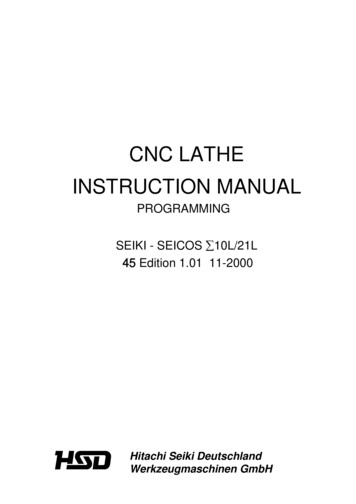
11DIMENSIONS11J Tech Photonics, Inc. www.jtechphotonics.comJune 25th, 2018V1.2 Copyright 2018
This breakout board is designed to work with the popular GRBL open source firmware for controlling CNC and laser machines. We have been very involved in the evolution of GRBL and this shield/breakout board is a simple and effective way to control a machine with GRBL. It offers easy