Transcription
CNC LATHEINSTRUCTION MANUALPROGRAMMINGSEIKI - SEICOS å10L/21L45 Edition 1.01 11-2000Hitachi Seiki DeutschlandWerkzeugmaschinen GmbH
2
IntroductionThank you for your having purchased the machine, favoring our product lines for your use.This manual contains fundamental information on the programming. Please read and fullyunderstand the contents for your safe machine operation.In particular, the contents of the items concerning safety in this manual and the descriptions on the“caution plates” attached to the machine are important. Please follow the instructions containedand keep them always in mind to ensure safe operation.The reference record papers on adjusting setting values such as a parameter list are attached tothe machine unit and enclosed in the packing. These are necessary for maintenance andadjustment of the machine later on. Please keep them safely not to be mislaid.The design and specifications of this machine may be changed to meet any future improvement.As the result, there may arise some cases where explanations in this manual could become partlyinconsistent with the actual machine. Please note this point in advance.In this manual, items on the standard and optional specifications are handled indiscriminately.Please refer to the “delivery note” for the detailed specification of your machine confirmation.1
2
CONTENTS1. PREPARATION FOR TOOL LAYOUT . 1 - 11-1 Tool Set . 1 - 21-2 Tool Layout . 1 - 61-3 NC Address and Range of Command Value . 1 - 72. PROGRAMMING . 2 - 12-1 Basis for Programming . 2 - 12-1-1 Program Reference Point and Coordinate Values . 2 - 12-1-2 Regarding Machine Zero Point . 2 - 22-1-3 Program Example. 2 - 32-2 Details of F, S, T and M Functions . 2 - 42-2-1 F Function (Feed Function) . 2 - 42-2-2 S Function (Spindle Function) . 2 - 52-2-3 T Function (Tool Function) . 2 - 72-2-4 M Function (Miscellaneous Function) List (TS15, HT20RIII/23RIII) . 2 - 112-3 Details of G Function . 2 - 332-3-1 List of G Function (SEICOS-S10L/20L) . 2 - 332-3-2 G50 Maximum Spindle Speed Setting . 2 - 362-3-3 G00 Positioning . 2 - 362-3-4 G01 Linear Cutting . 2 - 382-3-5 G02, G03 Circular Cutting . 2 - 402-3-6 G04 Dwell . 2 - 442-3-7 G09 Exact Stop . 2 - 442-3-8 G61 Exact Stop . 2 - 452-3-9 G10 Programmable Date Input . 2 - 452-3-10 G20, G21 Inch Input/Metric Input . 2 - 462-3-11 G22, G23 Stored Stroke Limit . 2 - 472-3-12 Stroke Limit Check Before Move . 2 - 502-3-13 G27 Reference Point Return Check . 2 - 512-3-14 G28 Automatic Reference Point Return . 2 - 522-3-15 G30 2nd Reference Point Return . 2 - 522-3-16 G31 Skip Function . 2 - 552-3-17 G54 Work Coordinate System Setting (Work Length) . 2 - 562-3-18 Canned Cycle . 2 - 572-3-19 G70, G71, G72, G73, G74, G75 Compound Repetitive Cycle (Option) . 2 - 662-3-20 G32, G92, G76 Thread Cutting . 2 - 82i
2-3-21 Continuous Thread Cutting . 2 - 1062-3-22 G34 Variable Lead Thread Cutting (Option) . 2 - 1062-3-23 Multi-thread Cutting (Option) . 2 - 1072-3-24 G150, G151, G152 Groove Width Compensation . 2 - 1083. AUTOMATIC CALCULATING FUNCTION OF TOOL NOSE RADIUSCOMPENSATION . 3 - 13-1 Outline . 3 - 13-2 Preparation to Execute the Automatic Calculating Function ofTool Nose Radius Compensation . 3 - 23-3 Three Conditions of Nose Radius Compensation . 3 - 33-3-1 Tool Nose Radius Compensation Block (During Cutting) . 3 - 43-3-2 Start-up Block and Compensation Cancel Block (Approach/Retreat) . 3 - 63-4 Caution Point of Approach to Workpiece . 3 - 103-5 Tool Nose Radius Compensation to Direct Designation G Code (G141, G142) . 3 - 114. PROGRAM EXAMPLE (NC PROGRAM) . 4 - 14-1 Chuck Work . 4 - 14-1-1 Machining Drawing . 4 - 14-1-2 Chuck Work Program . 4 - 24-2 Center Work . 4 - 64-2-1 Machining Drawing . 4 - 64-2-2 Center Work Program . 4 - 74-3 Bar Work . 4 - 94-3-1 Machining Drawing . 4 - 94-3-2 Bar Work Program . 4 - 104-4 Grooving . 4 - 124-4-1 OD Grooving . 4 - 124-4-2 ID Grooving . 4 - 134-4-3 End Face Grooving . 4 - 154-5 1st and 2nd Process Continuous Machining Method . 4 - 164-5-1 Machining Method by Single Program. 4 - 174-5-2 Machining Method by Subprogram Calling . 4 - 184-6 Operation Example of Many Short Length Works . 4 - 195. REFERENCE MATERIALS . 5 - 15-1 How to Calculate the Tool Nose Radius Compensation AmountWithout Using the Tool Nose Radius Compensation Function . 5 - 15-2 Calculation Formulas . 5 - 105-2-1 How to Obtain Side and Angle of Right Triangle. 5 - 105-2-2 How to Obtain Side and Angle of Inequilateral Triangle . 5 - 125-2-3 How to Obtain Taper and Intersecting Point of Circular Arc . 5 - 13ii
5-2-4 Others . 5 - 176. SPECIFICATIONS OF C-AXIS CONTROL (SEIKI-SEICOS S21L) . 6 - 16-1 Outline . 6 - 16-2 Standard Specifications . 6 - 16-3 Program . 6 - 36-3-1 Coordinate Axis . 6 - 36-3-2 Plane Selection of G17, G18, G19 . 6 - 36-3-3 Miscellaneous Function for Rotating Tool (M Code) . 6 - 46-3-4 Fixed Cycle for Hole Making G80 G89, G831, G841, G861 . 6 - 56-3-5 Program Example. 6 - 166-4 Polar Coordinate Interpolation Function . 6 - 236-4-1 Polar Coordinate Function . 6 - 236-4-2 G Function . 6 - 236-4-3 Program Example (X-axis : Linear axis/C-axis : Rotating axis) . 6 - 256-5 G40, G41, G42, G140, G143, G145 Tool Radius Compensation Function . 6 - 266-5-1 Direction of Tool Radius Compensation . 6 - 266-5-2 Movement of Tool Radius Compensation . 6 - 276-6 Program Example (Polar Coordinate Interpolation,Tool Radius Compensation Function) . 6 - 306-7 G824, G843 Direct Tapping . 6 - 326-8 G271 Cylindrical Interpolation . 6 - 357. REFERENCE(SPECIFICATIONS OF C-AXIS CONTROL) . 7 - 17-1 How to Calculate C-axis Feed Rate for Long Hole Machining . 7 - 17-2 How to Calculate the Number of Rotation and Feed Rate of the Rotating Tool . 7 - 3iii
iv
1. PREPARATION FOR TOOL LAYOUTThere are limit of range of travel and other limits according to the machinespecifications and safety.Refer to “Specifications Manual” of each machine type for stroke, workoperation range, tool interference diagram and Q setter work interferencediagram of the machine, which should be fully understood as they are premisesfor machine operation, programming and tool layout.1-1
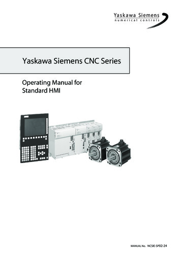
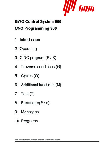
1-1 Tool SetStandard Tool SetIn order to keep operation procedure of the work and to avoid interference of the tool and thechuck large tools such as the base holder shall be set permanently.Further, set the tools as you like in order to satisfy the operation accuracy of the small toolssuch as the boring bar, and also to perform the turret indexing by one rotation.The standard tool set is shown as below.T08 ID groovingT07 OD groovingT06 ID rough boringT05 OD profiling or face groovingT09 OD and face finishingT04 DrillT10 ID finishingT03 OD profiling or face groovingT11 OD threadingT02 Center drill or Starting drillT12 ID threadingT01 Rough cuttingfor face and ODSpecifications of 12-station Variable turret
Standard Tool SetT06 ID groovingT05 OD groovingT07 OD and face finishingT08 ID finishingT04 ID rough boringT03 OD profiling or face groovingT09 OD threadingT10 ID threadingT01 Rough cuttingT02 Drillfor face and ODSpecifications of 10-station Variable turret
Standard Tool SetT06 ID groovingT05 OD groovingT07 OD and face finishingT08 ID finishingT04 ID rough boringT03 OD profiling orT09 OD threadingface groovingT02 DrillT10 ID threadingT01 Rough cutting for face and ODSpecifications of 10-station QCT turret1-4
Standard Tool SetT07 OD groovingT08 ID groovingT06 ID rough boringT05 OD profiling orT09 OD and face finishingface groovingT10 ID finishingT04 DrillT03 OD profiling orT11 OD threadingface groovingT02 Center drill or Starting drillT12 ID threadingT01 Rough cuttingfor face and ODSpecifications of 12-station QCT turret1-5
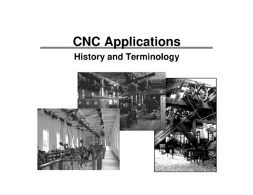
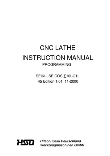
1-2 Tool LayoutExample of tool layout for chuck workCNC LATHE:TOOL LAYOUT DRAWINGProcess :Process 1, 2NC unitPart name SAMPLEMaterialS48CT1T3T5T7T9OD finishingOD threadingWidth 2mm R0.8R0.8OD groovingOD roughingT2T4T6R0.8φ30T8T10R0.8φ20 ID finishingφ20 ID roughing1-6φ25 ID threading
1-3 NC Address and Range of Command ValueFunctionAddressProgram No.Sequence No.ONPreparatory functionCoordinate valueGX, Y, Z, U, V,W, I, J, K, Q,R, A, B, CFeedrateSpindle functionFSTool functionAuxiliary functionTMDwellCall up program No.P, X, UPNumber of repetitionLRange of command value1 999999991 999999990 999 99999.999(mm) 9999.999(inch) 99999.999(deg) 99999.999(deg)0.001 999.999(m/rev)0.0001 99.9999(inch/rev)0 999999990 9999990 999999990 99999.999(sec)1 999999991 999999991-7
1-8
2. PROGRAMMING2-1 Basis for Programming2-1-1 Program Reference Point and Coordinate ValuesFor a CNC lathe, coordinate axes X and Z are set on the machine and their intersectingpoint is called a “program reference point”. The X axis assumes a spindle center line tobe a position of “XO”, and the Z axis assumes a workpiece finish end face on the tail stockside to a position of “ZO”.To move a tool, specify its moving position, adding signs “ ” and “ ” to both X and Z axes,with this program reference point as a datum point. Position of the tool A .Since it is locates a plus 50 dia. on the X-axis and plus 35mm (1.4”) on the Z-axis,X50.0 Z35.0 . (Omit the plus sign) Position of the tool B .Since it is locates a plus 80 dia. on the X-axis and minus 25mm (1.0”) on the Z-axis,X80.0 Z 25.02-1
2-1-2 Regarding Machine Zero PointProperly speaking, the machine zero point and reference point is a different position,however, as for our NC lathe make the both points the same position.Therefore, here in after the reference point calls as the machine zero point in this manual.It is a position which is the machine proper and the machine zero point which is the basisof program set the end of each axis.This machine zero point utilizes an electrically identical point, a grid point, and stop aservo motor at the certain point.Turn on the power at the starting time in the morning, it can be entered a programoperation by execution of the zero return.2-2
2-1-3 Program ExampleNC Program2-3
2-2 Details of F, S, T and M Functions2-2-1 F Function (Feed Function)G99 modeF ooo.ooo(Up to 6 digits in increment of 0.001)mm/rev Specify a cutting “feed rate” per spindle revolution or a lead of the threading.(Example) 0.3 mm/rev F0.3 or F301.0 mm/rev F1.0 or F1001.5 P thread F1.5 or F150In case of thread cutting, it is possible to command down to 5 digits of decimals.Fooo.ooooo(0.00001 unit; max. 8 digits)Whether lead designation or thread number designation should be selected for theaddress of E depends on parameter setting.When 8th place from the right of the parameter No.2403 is 0 . Lead designation.(Example)In case of 14 threads per inchFeed rate 25.4 1.814285714 threads 1.81429mm/rev F1.81429When 8th place from the right of the parameter No.2403 is 1 . (Thread numberdesignation)(Example)E14.0Max. feed rate 10,000mm/min.A maximum feed rate depends on the spindle speed used.Assuming the spindle speed to be N; 5000N(Example) When the spindle speed is 1,000 rpm, the maximum feed rate is;50001000G98 mode 5.0 F 5.0 mm/revFoooooo A decimal point cannot be used.mm/min Feed rate per minuteGenerally, you specify a feed rate per spindle revolution for in case of turning.However, if specified in the G98 mode, a feed rate per minute is set.(Example) 200 mm/min F200Notes) 1. Since the G99 mode is set when turning on the power, you do not have to specify it,unless G98 is to be used.2. A cutting feed in taper cutting or circular cutting is that of a tool advance direction(tangent direction).3. If a cutting feed in G98 mode (G01, G02, G03) is specified, the turret head moves evenif the spindle is not running.4. When commanding G98 from G99 mode or G99 mode from G98, be sure to command2-4
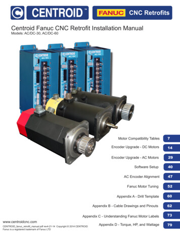
F . as well.In case of F command is missing in the block, F value is effective which is designatedjust preceding block in G98, G99 mode respectively.To be concrete, it becomes as follows:Indicate “F” that becomes effective in that block with [].(Feed per minute) (Feed per revolution)When the power is turn ON00.00N1 G99 F1.23 ;0[1.23]N2 —— ;0[1.23]N3 G98 F1000 ;[1000]1.23N4 —— ;[1000]1.23N5 G32 F2.34567 ;1000[2.34567]N6 —— ;1000[2.34567]N7 G99 ;1000[2.34]N8 —— ;1000[2.34]N9 G98 ;[1000]2.34N10 —— ;[1000]2.34N11 G32 ;1000[2.34567]2-2-2 S Function (Spindle Function)Specify a spindle speed or surface speed (cutting speed) with S 4-digit numeral(Soooo).CommandG50SooooDescriptionMax. spindle speed limit(Example) G50 S1800 : A maximum spindle speed is limited to 1,800 (mim 1)G97SooooConstant surface speed cancelSpecify a spindle revolution with Soooo .(Example) G97 S1000 : A spindle speed per minute is set to 1,000 (mim 1)G96SooooConstant surface speed controlWhen performing constant surface speed control, specify a cutting speed “V”(m/min) with an S 4-digit code (Soooo ).2-5
(Example)G96 S150: A spindle speed is controlled to 150150 m/min cutting speed at the cutting point. Refer to the left figure.* Formula for calculating the spindle speed from thesurface speedN 1000 Vπ DV : Surface speed (m/min)π : 3.14D : Tool nose position (φ mm)N : Spindle speed (mim 1)Spindle speed “N” at the position A 1000 150 1193 (mim 1)3.14 40φSpindle speed “N” at the position B 1000 150 795 (mim 1)3.14 60φSpindle speed “N” at the position C 1000 150 682 (mim 1)3.14 70φAs mentioned above, an automatic change of the spindle speed relating to the workdiameter is called as the constant surface speed control.Notes) 1. Considering a workpiece chucking condition, specify the maximum spindle speed limitwith S 4-digit code in a G50 block at the beginning of a program.2. When roughing with G96, calculate maximum and minimum spindle speeds so thatcutting will be performed in a constant power range as much as possible.3. When changing over from G96 to G97 and vice versa, specify not only a G code, butalso an S code.4. When changed over from G96 to G97 and no S code is specified, the spindle is run withthe speed specified in the latest S code in G96 mode.5. When changed over from G96 to G97 and no S code is specified, the spindle turns withthe previously used surface constant speed is S code had been specified in G96 mode.Also, when no S code is specified in G96 mode, S results in 0.6. The following interlocks are provided as the rotating conditions of spindle.(1) The direction of the chuck inner clamp and outer clamp key shall be the samedirection as that of chuck clamping.(2) Q-setter shall be stored.(3) Rotating speed shall be command with G96 Sxxx.(4) The lamp of advance or retract of center support shall be on. (Option)(5) The door shall be closed.2-6
In case of rotary tool, there are four additional interlocks as follows.(1) The connection of C-axis shall be in the status of OFF (M40 command). (Option)(2) The connection of rotating tool shall be in the status of OFF (M45 command).(Option)(3) Set up of the ACT shall be cancel condition. (Option)(4) The safety door of the ATC magazine shall be closed. (Option)2-2-3 T Function (Tool Function)The tool used and its offset No. can be selected with a 4-digit number following “T”.Too Turret face selectionOffset No.Face 01 maximum number of faces1. Setting Coordinate of Tool-nose PositionAs a general usage, it is not necessary to command of offset No. Only command ofcalling of turret as shown below can set the tool-nose position.Example) If the turret No. 3 is to be called, program as follows:T03002. Setting Coordinate of Tool-nose Position for Arbitrary Offset No. When using anarbitrary offset No., program as follows.Setting is done with the tool mounting position (diameter, length) of the offset No. 13.Example)T0313Turret No. 3Offset No.selectedNote 1. Be sure to input the tool-nose point on the tool layout screen.2. Input “9” to the tool-nose point for drilling end-milling tool. (When a rotating toolis equipped.)CautionWhen “Too ” command is specified on the same line as the axis travelcommand, the indexing of turret is made simultaneously with traveling and acoordinate is set after completion of traveling.Be careful not to command T function together with the travel command.2-7
3. Compound OffsetWhen an adjustment is made on diametrical dimension of 50 and 70mm respectively atthe following workpiece, two or more offset can be applied on one tool.Example 1)T0900G97 S2546G00 X50.0G96 Z3.0G01 Z 15.0M08Z10.0 M03S200F0.2X70.0 T0919Compound offsetZ 40.0Offset No. 19X84.0 T0900Compound offsetG00cancelG97 X200.0 Z200.0 S500M01Example) Input status of dimension adjustment when the part φ70 is made larger by0.03.TOOL LAYOUTOFFSET19X0.03Z0R0T0Note) Be sure to input zero for R and T.Example 2)Cutting with taper of 0.3 at φ30 partT0500G97G00G01G00OFFSET25 X 0.3 Z0 R0 T02-8S2000Z3.0X40.0X24.0Z1.0X30.0Z 90.0M08M03F1.0F0.2Z 2.0T0525X57.00 T0500X62.0 Z 92.5X200.0 Z5.0M01Compound offsetOffset No. 25Compound offsetcancel
4. Multi tool compensationWhen set up tools 2 or more on the same face on the turret described below, giveplural compensation on a face and set up the coordinate for each tool respectively.Command system of compound compensation, and furthermore, set up tools deem asdifferent one by setting data in nose radius and control point.T0100〜(Example) N100〜T0131A tool with turret face No.1 is indexed and setting-upis performed by the data of offset No.1.A tool with turret face No.1 is indexed and setting-upis performed by the data of offset No.31.Note 1) When a tool, which is not required tool point and tool nose R such as drill etc., isapplied to multi tool, set a tool point as 9. (Tool nose R may be set as zero.)2) When set the Q setter, the cursor position of tool offset coincide with the tool No.mounted on the turret face indexed at machining position at this moment.Any No. can be selected by moving the cursor by cursor key.Multi tool compensation and compound compensation is divided by data of toolpoint and tool nose R as follows:Tool nose R and tool point of offset No. on effect the compound compensationand multi tool compensation.1 Both tool nose R and tool point are zero Compound compensation2 Data of tool point from 1 to 9 and setting of tool nose R3 Tool point is zero and set a tool nose R2-9 Multi tool cutting Alarm (No.182)
D. Program exampleT06T01T03Turret face No.1Turret face No.3Offset No.1Offset No.3Turret face No.6(Compound compensation 33, 34)T0100The turret face No.1 is indexed and setting-up is〜N100(Offset No.6, 36)performed by the data of offset No.1.M01T0300The turret face No.3 is indexed and setting-up is〜N300Z T0333Compound compensation ON (Offset No.33)〜G01performed by the data of offset No.3.ZT0334Compound compensation ON (Offset No.34)〜XCancel compound compensation〜T0300M01T0600The turret face No.6 is indexed and setting-up is〜N600Compound compensation ON (Offset No.36)Multi tool compensation ON (Offset No.36)〜T0636M01Example of compensating r0.8306Q-setterQ-setter0.4233Extremelysmall amountExtremelysmall amount00Extremelysmall amountExtremelysmall amount00Q-setterQ-setter0.4234362 - 10
2-2-4 M Function (Miscellaneous Function) List (TS15, HT20RIII/23RIII)Please refer to the details on the Delivery specificationsas to the discrimination between Standard or Option.M codeM00FunctionProgram stopDescriptionThis code can stop the machine during its operation,when measuring a workpiece or removing cutting chips.(The spindle and coolant also stop.) To restart, pressthe CYCLE START key. However, since the spindleand coolant are being suspended, specify M03/M08 in asubsequent block.M01Optional stopSame function as M00.An M01 command on a program can be either executedor ignored by means of the OPTIONAL STOP key onthe operation panel.Executed when a lamp is lit up.(optional stop is effective)Sheet keyIgnored when a lamp is lit off.(optional stop is not effective)M02Program endThis code is used in the tape operation and isprogrammed at the end of the program.It stops the spindle and coolant, and resets NC.M03Spindle forward start Viewing from the tailstock side, this code starts thespindle in the counterclockwise direction.M04Spindle reverse start Viewing from the tailstock side, this code starts thespindle in the clockwise direction.M05Spindle stopThis code stops the spindle.When changing over spindle revolution from forward toreverse (or the other way), stop the spindle once withM05, and then specify M04 (M03).M08Coolant startThis code starts discharging coolant.M09Coolant stopThis code stops discharging coolant.M12Work count (toolNormally, this code starts a work counter or tool countercount)to count up.Note) : M05 and M09 are executed after the completion of the axes travel. Do not specify M codes in the same block duplicately.2 - 11
M codeM18FunctionDescriptionRelease the spindle Release the spindle positioning.PositioningM19Spindle PositioningThe spindle can be position at the one point.M23Chamfering ONThis code performs automatic thread chamfering during(automatic threada threading cycle (G92). A chamfering length can be setchamfering)in the parameter in increment of 0.1 L.When M23 is specified.M24Chamfering OFFThis code cancels M23.M25Tailstock lowLow speed advance until advance end. The commandspeed advanceis completed when work pushed and hydraulic becomeON. But, alarm is on when work is not under pushingwithin the time set by timer.(D1006).M26Tailstock high speed Completed when tailstock retracted at high speed forretractM27the time set by timer setting table. (TMR011)Tailstock high speed Completed when tailstock advanced at high speed foradvancethe time set by timer setting table. (TMR007)Don’t touch work by command of high speed advance.M28Tailstock retract end The tailstock moves the retract end.M30Program endThis code is used instead of M02 in case of(memory operation) memoryoperation. In addition to the function of M02,this code returns the program to the top.(Specify in an independent block.)M31No-workpiece chuck 1) Tool life check.Number check2) Machined work number check by preset typeworkcounter.3) When a bar feeder is equipped, non blank check.2 - 12
M codeM32FunctionTop cut chuckDescriptionBlock ship ON, however, block skip becomes OFF bythe top cut signal ON.M33Top cut resetReset the top cut signal.M34ProgrammableProgrammable tailstock pushes work.tailstock advanceM35ProgrammableProgrammable tailstock stops pushing work.tailstock retractM36Power off is effective Power is off by command of M00, M01, M02 or M30at program stopwhen the power cut off is ON.Power off is notM37effective at program Power does no
CNC LATHE INSTRUCTION MANUAL PROGRAMMING SEIKI - SEICOS 10L/21L 45 Edition 1.01 11-2000. 2. 1 Introduction Thank you for your having purchased the machine, favoring our product lines for your use. This manual contains fundamental information o