Transcription
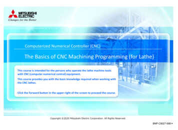
Computerized Numerical Controller (CNC)The Basics of CNC Machining Programming (for Lathe)This course is intended for the persons who operate the lathe machine toolswith CNC (computer numerical control) equipment.This course provides you with the basic knowledge required when working withthe CNC lathes.Click the Forward button in the upper-right of the screen to proceed the course.Copyright 2020 Mitsubishi Electric Corporation. All Rights Reserved.BNP-C8027-688*
IntroductionObjectives of this courseThis course describes the basic knowledge of CNC Lathe machining program and how to use the common instructions to theCNC control.The goal of this course is to help you to be able to prepare the basic machining program with referring the manuals of yourCNC or machine tool.
IntroductionContents of this courseThe contents of this course are as shown below.Chapter 1 The basic knowledge for programmingThe terms and commands you should know before learning CNC programmingChapter 2 Positioning and interpolationThe basic instructions needed to move axesChapter 3 Coordinate systemConcept of coordinate system on machine toolFinal testScore to pass: 70% or more
IntroductionHow to use this e-Learning toolGo to the next pageGo to the next page.Back to the previous pageBack to the previous page.Move to the desired page"Table of Contents" will be displayed, enabling you to navigate to thedesired page.Exit the learningExit the learning.
IntroductionFor your safety Safety precautionsWe recommend using MITSUBISHI CNC software for training (NC Trainer2) to verify your CNC machining program operation.NC Trainer2 allows you to check how your program runs within your PC environment but without actual machine.In case you attempt to verify your program with machine tool, be educated about the operations and safety of yourmachine tool and be thoroughly familiar with your machine tool prior to using.Note that the CNC instruction format may vary from one MTB to the next because they have to meet them to their ownspecific features of the machines.Thus, the CNC functions and command formatting shown in this course may NOT be applicable to the ones used on yourmachine tool.In this case, please give the first priority on the manual issued by your machine tool builder.
Chapter 1 The basic knowledge for programmingThis chapter discusses the terms and commands you should know before learning CNC programming.1.1 Configuration of the machine tool (CNC Lathe)1.2 The axes of CNC Lathe1.3 Format of machining program1.4 Address1.5 Sequence number1.6 Preparatory function (G code)1.7 Spindle function (S code)1.8 Tool Function (T code)1.9 Miscellaneous function (M code)1.10 Comment
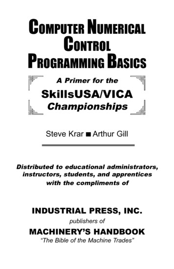
1.1Configuration of the machine tool (CNC Lathe)Lathe is a type of machine tool that removes the material from rotating workpiece (the stock to be machined) with cuttingtool (single point tool, or tooling/drilling bits) to make the workpiece form a desired shape.CNC lathes generally consist of various equipment such as the chuck to hold the workpiece, spindle and its motor to rotate theworkpiece, servo motor(s) to move the cutting tool to the machining points.SpindleChuckWorkpieceCutting tool (single point tool)Tool postFeed screwSpindle motorBeltServo motor
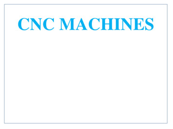
1.2The axes of CNC LatheLathe has the coordinate system to designate the positions required for machining the workpiece.As shown below, the vertical direction is called X axis, and the horizontal direction is called Z axis. The X axis and the Z axisform the right angle.X axis direction of motionX axisZ axis- direction of motionCutting tool (single point tool)Z axis direction of motionX axis- direction of motionChuckWorkpieceZ axis
1.3Format of machining programMachining program is a measure to tell the CNC how and in which order it makes the machine tool move.The primary unit of CNC command that constitutes the machining program is made in the combination of an alphabeticalletter and the numerical value.This primary unit (alphabetical letter numerical value) is called a “word”.The alphabetical letter at the head of a word is called an ical value
1.3Format of machining programIn the formatting of machining program, one or more “words” (commands) constitute one line.The sign of new line at the end of a line is shown as “;” on CNC display screen.One line of machining program is called a “block”.Write “%” at the end of the machining program.The machining program will be executed block by block.WordN1N2N3N4N5N6N7:%G28 U0 ;G28 W0 ;G50 S2000 ;T0101 ;G96 S180 M03 ;G00 X10. Z5. M08 ;G99 G01 Z-5. F0.3 ;End of blockBlockEnd of program
1.4AddressLet’s discuss the various “address” that composes each word prior to looking into the primary unit of machining program“word”.Address has the specific name and meaning as shown below.WordExample of AddressAddressApplicationsNBlock line int designation to whichthe axis movesSFeedrate/speed designationof the axisTTool DesignationMMiscellaneous functionG28X-1.234AddressNumerical valueNext, let’s discuss how to use the “word”, the combination of address letter and numerical value.
1.5Sequence Number“N” is the address to be used to visually identify a certain machining content (block) by the programmer/operator.“N” is called as “Sequence number” when accompanied by the numerical value.This sequence number can be used to identify the location of the executing block of the program.The display screen of the CNC control shows the status of the CNC operation.When you run a program, the sequence number of currently running block will appear on the display.Note that the sequence number on the screen is retained even after it is executed, so the latest sequence number the control ran willappear even while the control is running other blocks with no sequence numbers (N).N1N2N3N4N5N6:G28 U0 ;G28 W0 ;G50 S2000;T0101 ;G96 S180 M03 ;G00 X10. Z3. ;* You do not have to use the sequence number in every block.
1.6Preparatory function (G code)“G” is the letter address to be used to tell the control preparatory-purpose command.The word “G” accompanied by a numerical value is called preparatory function, G function, or G code(s).There are the types of G codes as shown in table below, and they have group for each function.Example of G codeG G9805G9905::DescriptionPositioning (Rapid motion command)Linear interpolation (Cutting feed command)Circular interpolation (Clockwise)Circular interpolation (Counterclockwise):Dwell:Plane selection, X-YPlane selection, Z-X:Feed per minuteFeed per revolution (Synchronous feed):
1.6.1Preparatory function (G code): Modal and non-modal (unmodal)G codes can be roughly classified into two. Let’s see this using switch analogy.Modal commandThe G codes other than group 00, such like group 01 or 02, are to be used to restate the mode within the same group. These G codes arecalled Modal command.You do not have to restate the modal command except when you need to change the modal.G02G01Group01: Specify the preparatory functionG03G00・・・G code GroupDescriptionG0001Positioning (Rapid motion command)G0101Linear interpolation (Cutting feed command)G0201Circular interpolation (Clockwise)G0301Circular interpolation (Counterclockwise):::Non-modal (unmodal) commandG code in Group 00 is only valid within one block. This kind of G code is called Non-modal (unmodal) command.Non-modal (unmodal) command must be repeatedly written for every block even when commanding the same instructions.G04CommandedNotcommandedG code GroupDescriptionG0001Positioning (Rapid motion command)G0101Linear interpolation (Cutting feed command)ONG0201Circular interpolation (Clockwise)G0301Circular interpolation (Counterclockwise):::G0400DwellOFF* G04 (Dwell) is a non-modal (unmodal) G code that provides the dwell period for the axis move.See 2.8 for the detail of dwell command.
1.7Spindle function (S code)“S” is the letter address to be used to tell the control the spindle rotation speed.The word “S” accompanied by a numerical value is called spindle function, or S function.The numerical value after the letter address is to specify the angular velocity of the spindle (rev/min) (number of revolutionsof spindle per minute).When the speed of spindle is 500 revolutions per minute (500min-1), write as shown below.S500 ;The spindle cannot start rotation only by writing the S command.To make the spindle start the rotation, add M03(clockwise rotation) or M04(counterclockwise rotation). (See 1.9 for detail of the commandusing address letter M.)To instruct the spindle speed and the start of clockwise rotation within one block, write as shown below.S500 M03;To stop the spindle rotation, command M05.M05;
1.8Tool Function (T code)“T” is the address letter to be used to select the tool.The word “T” accompanied by a numerical value is called the tool function or T code.The four digit-numerical value after the address T runs the following two functions. Select tool Tool length compensationT0202;5Tool length compensation number. The tool compensation data corresponding to thespecified number will be added to the position of theaxis once this command is issued.Tool number you want to use The turret moves to make the tool available to use.6748321
1.9Miscellaneous function (M code)“M” is the address used to instruct the CNC control to perform miscellaneous functions of the machine tool such like the ON and OFF ofspindle (CW/CCW), turning on/off the coolant.The word “M” accompanied by a numerical value is called the miscellaneous function or M code.There are the types of M codes as shown in table below.Example of M codeM codeFunctionDescriptionProgram stopHalts the execution of the program.M01Optional stopHalts the execution of the program.You can choose not to halt the program execution with thecorresponding switch on the machine operation panel.M02End of programTells the control the end of execution of the machining program.M03Spindle on (clockwise)Turns on the spindle rotation in clockwise.M04Spindle on(counterclockwise)Turns on the spindle rotation in counterclockwise.M05Spindle stopTurns off the spindle rotation.M30End of programTells the control the end of execution of the machining program.M00* The machine behaviors and function assigned to each M code may vary from one machine tool to the next.You must check in the machine tool builder's manual to determine a machine's behaviors and function prior to using M code.
1.10CommentThough this is not categorized to “word” discussed to this point, you can use “comment” function when you want to add thedescription to describe the meaning or notes in your machining program.The comment can be used to inform the other people of what the program is intended to do.So it can be a help when you review your program later, or even when you read the program prepared by the otherprogrammer.The description enclosed in the parentheses “(“ and “)” is regarded as the comment. You can use alphabet, numerical value,and symbols to write the comment.You can use whole of one line to write a comment. You can also add comment after writing a commands.N1 G28 U0 ;N2 G28 W0 ;(COMMENT-1) ;N3 G50 S2000 ;N4 G40 G80 G54 G18 ;N5 T0101 (COMMENT-2) ;N6 G96 S180 M03 ;:
Chapter 2 Positioning and interpolationIn this chapter, we will discuss the basic instructions needed to move axes.2.1 How to command position: Absolute mode and incremental mode2.2 How to command position: Specify in diameter2.3 How to command position: Use of decimal point in numerical value2.4 Positioning command: G00 (Rapid)2.5 Linear interpolation: G01 (Cutting feed)2.6 Feed rate (F command)2.7 Circular interpolation : G02, G032.8 Dwell: G04
2.1How to command position: Absolute mode and incremental modeFor the machining of workpiece, it is necessary to move the tool to the intended position.In CNC program, the axes move on the machine tool is instructed by the designation of both the target axes to move and thedestination of the axes.There are two kinds of positioning mode; “Absolute mode” to specify the destination with the coordinates. “Incremental mode” to specify the amount of motion relative to the previous position.In general, we choose the best mode depending on how the dimensions on a drawing are specified. Absolute mode: When the destination is being specified with its coordinates. Incremental mode: When the destination is being specified with the amount of motion relative to the current position.Following shows how to determine which mode to choose when you move the tool from point A to point B.Incremental modeAbsolute mode110230A0B230Move the tool tocoordinates 230.A0To specify the destination of positioning, use address X, Z and U, W discussed in Chapter 1.Next, let’s look at the detail of how to command position.B230Move in positivedirection 110 frompoint A.
2.1.1How to command position: Absolute modeWhen using absolute mode, write the address letter(s) (X, Z) corresponding to the axis to move to specify the coordinates of thedestination.The machining program shown below is the example when moving the tool tip from the current position of point A to point B, whosecoordinates is (X, Z) (10.0, 20.0).In absolute mode, the command to be used is identical in both cases either when moving the tool from point A to point B or whenmoving from point A’ to point B.X10. Z20. ;X40.Point A30.20.Point A’Point B10.0X5.10.15.20.25.Z30.Z
2.1.2How to command position: Incremental modeIn incremental mode, we use address U and W as the axis address. Address U corresponds to X axis direction, and the address W to Z axis.The machining program shown below is the example when moving the tool tip from the current position point A (20.0 , 5.0) to point B(10.0 , 25.0).You must use the address letters (U and W) respectively corresponding to the X-axis and Z-axis, and also the amount of motion(Coordinates of point B - coordinates of point A) (10.0-20.0, 25.0-5.0) (-10.0 , 20.0). When the direction of motion is negative, add minus(-) symbol to the amount of motion.In incremental mode, the destination is specified by the amount of motion relative to the position at commanding, thus the command (U10. W20) moves the tool to point B when it is told at point A, but moves the tool to point B’ when it is told at point A’.U-10. W20. ;X(U)30.20.Point A’Point A-10.Point B10.20.05.10.15.Point B’20.20.25.30.35.40.45.50.Z(W)
2.2How to command position: Specify in diameterIn general, for the lathe machines the cylindrical workpiece, so the position along X axis is specified as the diameter-basis concept.Following shows how to specify the position in X axis when you move the tool from point A to point B. When in absolute mode (X), two times of r1 When in incremental mode (U), two times of r2XZDiameterXPoint APoint BSpindler2r1r12r1ZAbsolute mode: X2r1Incremental mode: U2r2
2.3How to command position: Use of decimal point in numerical valueCNC machine tool distinguishes in which unit the command are told, depending on the use of decimal point in the numericalvalue after the address (such like X, Z, U, W and F) being used to specify the amount of motion, coordinates, angle, period oftime, or speed. With decimal point: in mm Without decimal point: in μmThe drawings are commonly written in mm, so add decimal point when preparing your machining program. With decimal pointX123. is identical to X123000. (Corresponds to the position 123.000mm in X axis.) Without decimal pointX123 is identical to X0.123 in X axis. (Corresponds to the position 0.123mm in X axis.)One of the most common failure in the machining program is to leave out the decimal point.If the CNC control is told "X10" despite the programmer wanted to write X10.000, the CNC control behaves as it is told"X0.010".
2.4Positioning command: G00 (Rapid)The tool moves to the specified position by X and Z (respectively U and W) within the command, and the type of motion is inaccordance with the G code.When you want to rapidly move the tool without interfering with the workpiece, such as in the case the tool moves to the startingpoint of machining on the workpiece, use G00 (Positioning) command. G00 is a command to move the tool to the specified positionat rapid rate and is also called rapid positioning command.* The rapid rate is determined in the machine tool builder’s manual. You must check in the machine tool builder's manual for detail.Together with G00, it is necessary to designate the destination point using X and Z or U and W.When to run rapid positioning from point A to point B, tell the machine as shown below.Absolute mode: G00 X10. Z25. ;Incremental mode: G00 U-20. W15. 5.10.15.20.PointB25.30.Z
2.5Linear interpolation: G01 (Cutting feed)To perform cutting by the linear axis motion on the workpiece, G01 (Linear interpolation) command will be used.Together with G01, it is necessary to designate the destination point using X and Z or U and W. Then the tool moves along astraight line toward the destination point specified.In G01 command, it is also necessary to specify the feedrate (F) to be applied during the axis move, in addition to theinstruction to move the axes.* Details of feedrate will be discussed in 2.6.When to run cutting operation from point A to point B along a straight line, tell the machine as shown below.Absolute mode: G01 X10. Z25. F0.3 ;Incremental mode: G01 U-20. W15. F0.3 ;Linear interpolationXDestination40.Point A30.20.-20.10.15.05.10.15.20.PointB25.30.ZFeedrate
2.6Feed rate (F command)During G01 (Linear interpolation) presentation, we discussed that the G01 is used when the axis moves while performing the cuttingoperation, and also mentioned that the feedrate applied in the cutting operation must be instructed.To specify the feedrate, use the address letter F and the distance per revolution (mm/rev) (also called feed per revolution).To specify the feedrate of G01 at 0.3mm per revolution in spindle, write as shown below.G01 Z-10. F0.3 ;The numerical value specified together with the address F is retained once it is specified.So you can omit the feedrate underlined as shown below when you would like to use the same feedrate during the consecutivecommands.G01Z-10. F0.3G01 X10. Z-20. F0.3G01Z-30. F0.3G01 X20. Z-10. F0.5:;;;;Feedrate0.3mm/rev0.5mm/revFor the target we discuss in this course is the lathe, the unit of the feedrate is presented in the distance per spindle revolution(mm/rev). But in some cases, there are the machining operations that allows to use the unit in the distance per minute (mm/min)(feed per minute).To change the unit of the F command, use appropriate G code. Reference the machine tool builder’s manual or CNC manufacturer’smanual for detail.
2.7Circular interpolation : G02, G03For the cutting operation in a straight line motion, we adopted G01 (Linear interpolation).Now let’s discuss the command that is used for the cutting operation along a circular motion.To perform cutting by the circular axis motion on the workpiece, G02 or G03 (Circular interpolation) command will be used.G02 can run machining motion in the form of a clockwise (CW) arc path, on the other hand G03 in the form of a counterclockwise(CCW) arc path.As with G01, both G02 and G03 require the destination point (X and Z, or U and W) and feedrate (F).Additionally, circular motion requires the radius of the arc being specified by programmer, using address letter R.To run CW circular cutting operation from point A to point B at the radius of 15.0[mm], tell the machine as shown below.G02 X30. Z5. R15. F0.3 ;Clockwise DestinationRadiusFeedrateX40.Point B30.G02ClockwiseG03CounterclockwiseR 15.20.Point A10.05.10.15.20.25.30.Z
2.8Dwell G04This G code is used to provides a waiting for the axis move with giving a dwell period.For example, it is necessary to temporary pause the axis motion during performing cutoff operation, to prevent the insufficient cutting at thebottom of the cutoff, or to remove the remaining material.The command to be used in such case of machining is called Dwell command (G04).Let’s discuss the case that runs the cutoff operation using G01 command.When the consecutive G01 commands (linear interpolation) exist, the CNC control decelerates as the axis reaches close to the positionspecified in the first block and prepares for the acceleration for the next block as shown in figure (A) to smoothen the axis motion at thepoint between the two blocks.As the angle made by the two blocks gradually decreases as shown in (A), (B) and (C), the axis starts the motion of the second block withoutreaching the specified position in the first block. Thus the machine behavior shown in (C) induces an insufficient cutting.In addition, if the tool does not make at least one revolution around the axis with keeping its position at the bottom of the flute, theinconsistent surface may caused.But when the Dwell command (G04) exist between the two blocks, you can avoid this kind of insufficient cutting.G01InsufficientcuttingG01(A)Boundary betweentwo blocks(B)(C)G04Not commandedG01G01(D)G04Commanded
2.8Dwell G04 (Specifying the dwell period)Dwell (G04) causes the axis to pause for a specified period.The dwell period is specified using the address P or X. When using address P, the period is specified in 1/1000 sec. No decimal point in this value. When using address X, the period is specified in sec. Use decimal point in this value.When specifying the 1.5 sec pause in dwell command, tell the machine as shown below.Address P: G04 P1500 ;Address X: G04 P1.5 ;G01G01:G01 X10. F100. ;G04 X1.5 ;G01 X50. ;:Pause for 1.5 secDwell command (G04) allows to specify the period to pause using the number of revolution of the spindle.Because the cutting operation on lathe is commonly performed in feed per revolution, the dwell period is generally specifiedin the number of revolution.
Chapter 3 Coordinate systemIn this chapter, we will discuss the coordinate system on CNC machine tool.3.1 Coordinate system3.2 Workpiece coordinate system offset3.3 Reference position and reference position return: G28
3.1Coordinate systemCNC machine tool has coordinate systems, called Machine coordinate system and Workpiece coordinate system.The machine coordinate system is used to instate the positions specific to the machine tool.The “Machine position” counter shown on the monitor screen of CNC unit displays the coordinates in the machine coordinatesystem.The position at which the “machine position” counter displays zero is called machine coordinate origin.The workpiece coordinate system is commonly used when writing the machining program.The position (X, Z) (0, 0) in the machining program is called workpiece coordinate origin.The “Workpiece coordinate position” counter shown on the monitor screen of CNC unit displays the coordinates in theworkpiece coordinate system.X axis Machine coordinate systemWorkpiece coordinate systemXZMachine position counterZ axisMachine coordinate originWorkpiececoordinate originWorkpiececoordinateposition counter
3.2Workpiece coordinate system offsetThe position of workpiece coordinate origin in the machine coordinate system is specified with Workpiece coordinate system offset.The workpiece coordinate system offset can be specified with the CNC unit's setting screen of the coordinate system offset.Setting screen of workpiece coordinate system offsetX axisMachine coordinate systemWorkpiece coordinate systemXWorkpiece coordinatesystem offsetZMachine coordinate originZ axisWorkpiece coordinate origin(Program zero)
3.3Reference position and reference position return: G28Reference position is a specific point defined by a coordinates in the machine coordinate system, and is utilized as the point atwhich the machine is told as the start point of motion.To move the tool to reference position, we use G28 (Reference position return).By the axis letter address in absolute mode (X, Z) included in G28 command, you can specify the intermediate position(intermediate point) to which the axis will first move prior to moving to the reference position. This intermediate point is usedto avoid unintended interference between the tool and the workpiece.For example, the command shown below tells the machine to first move the tool from point A to (X, Z) (150.0, -200.0) then tomove the reference position.G28 X150. Z-200. ;Machine coordinate systemReferencepositionWorkpiece coordinate cecoordinate origin
3.3Reference position and reference position return: G28In case you would not like to specify the intermediate point, use zero in incremental positioning (U0, W0) in G28 to directly movethe tool to the reference position. In this case, it is generally preferred to move the axis one by one to avoid unintendedinterference between the tool and the workpiece.Following show the example when moving the X axis and Z axis independently to reference position.G28 U0 ;G28 W0 ;X axisMachine coordinate system Move to reference position in Z axis onlyG28 W0Move to referenceposition in X axis onlyG28 U0Reference positionSimultaneously return to reference position in X and Z axesG28 U0 W0InterferenceZ axis
3.4Summary of this courseTo summarize the whole contents of this course, here is the example machining path and its corresponding machining program.N12N11N9X40.30N8.20N7N6 .10R12.5.5.-30. -25. -20. -15. -10. -5.Program(REVIEW-PROGRAM) ;N1 G28 U0 ;N2 G28 W0 ;N3 G50 S2000 ;N4 G40 G80 G54 G18N5 T0101 ;N6 G96 S180 M03 ;N7 G00 X10. Z5. ;N8 G99 G01 Z-5. F0.3 ;N9 G03 X20. Z-15. R12.5 ;N10 G01 Z-20. ;N11 G01 X40. ;N12 S0 M05 ;N13 G28 U0 ;N14 G28 W0 ;N15 M02 ;%N5Z10.MessageThis is the comment or notes in program. (1.10)Moves the X axis to reference position. (3.3)Moves the Z axis to reference position.Defines the maximum spindle rotation speed at 2000[rev/min].Initializes the current modal.Selects the tool at reference position. (1.8)Turns on constant surface speed control prior to starting cutting operation, then turn on the spindle.(1.9)This is NOT the cutting operation, but the positioning command at rapid rate. (2.4)Cutting operation along the straight line at the rate in feed per revolution. Feedrate required. (2.5)Runs circular cutting operation. Specifying the radius is required. (2.7)Cutting operation along the straight line. F command can be omitted.G01 is the modal command, and not necessary to write again except when you need to change the modal.Turns the spindle off after the completion of cutting operation. (1.9)Moves to reference position.First moves the Z axis to reference position in X(U) axis like above, then in Z(W) axis. This reduces the risk ofinterference with the workpiece.End of program (1.9)End of program (1.3)
TestFinal TestNow that you have completed all of the lessons of The Basics of CNC Machining Programming (for Lathe) course, youare ready to take the final test. If you are unclear on any of the topics covered, please take this opportunity to reviewthose topics.There are a total of 10 questions,(10 topics) in this Final Test.You can take the final test as many times as you like.How to score the testAfter selecting the answer, make sure to click the Answer button. Your answer will be lost if you proceed withoutclicking the Answer button. (Regarded as unanswered question.)Score resultsThe number of correct answers, the number of questions, the percentage of correct answers, and the pass/failresult will appear on the score page.To pass the test, you have toanswer 70% of the questionscorrect. Click the Proceed button to exit the test. Click the Review button to review the test. (Correct answer check) Click the Retry button to retake the test again.
You have completed the Computerized Numerical Controllers (CNC)The Basics of CNC Machining Programming (for Lathe) Course.Thank you for taking this course.We hope you enjoyed the lessons and the information you acquired inthis course will be useful in the future.You can review the course as many times as you want.
The Basics of CNC Machining Programming (for Lathe) Computerized Numerical Controller (CNC) This course is intended for the persons who operate the lathe machine tools with CNC (computer numerical control) equipment. This course provides you with the basic knowledge re