Transcription
EML 2322L -- MAE Design and Manufacturing LaboratoryCNC MachiningIntro to CNC Machining CNC stands for computer numeric controlled. It refers to anymachine tool (i.e. mill, lathe, drill press, etc.) which uses a computerto electronically control the motion of one or more axes on themachine. The development of NC machine tools started from a task supportedby the US Air Force in the early 1950’s, involving MIT and severalmachine-tool manufacturing companies. The need was recognizedfor machines to be able to manufacture complex jet aircraft parts. As computer technology evolved, computers replaced the moreinflexible controllers found on the NC machines; hence the dawn ofthe CNC era. CNC machine tools use software programs to provide the instructionsnecessary to control the axis motions, spindle speeds, tool changesand so on. CNC machine tools allow multiple axes of motion simultaneously,resulting in 2D and 3D contouring ability. CNC technology also increases productivity and quality control byallowing multiple parts to be produced using the same program andtooling.
Basics of CNC ProgrammingThere are two ways to program modern CNC machine tools.1. Conversational Programming. This is the simpler of the twomethods. In effect, this is a macro programming language used toinstruct the machine to perform pre-programmed cycles (i.e.facing, drilling holes in arrays, etc.). When writing aconversational program, you simply enter the appropriateparameters associated with each machining cycle. This isanalogous to using the polar array function in SolidWorks orPro/E; you don’t have to do the layout or trig to find the locationof the features; you just specify the essential parameters and thesoftware does the rest for you.2. CAM Programming. This is the more powerful of the twomethods. Using this method, you import your part model into aCAM (computer aided manufacturing) program and define theparameters associated with each and every machined feature on thepart. These parameters include tool diameter and length, depth ofcut, tool path geometry, etc.
Conversational CNC ProgrammingThe following cycles are typical of the machining operations availablewhen programming a 3-axis CNC milling machine.Position. Used to move the XYZ coordinates at rapid feedrate.Drill one. Used to position the tool at a specific XYZ coordinateposition in order to automatically drill a hole. The automatic drill cyclesallow for simple drilling, peck drilling, spot-facing and bore cycles.Drill pattern. Used to define polar or rectangular hole arrays forautomatic drilling.Line. Used to cut straight lines along an axis or a diagonal at the desiredfeedrate.Arc. Used to cut a circle or partial circle that is part of a series of cutsthat usually includes lines as well.Face. Used to define a rectangular zig-zag pattern used to clean off apart surface.Pocket. Used to clear the material out of a rectangle, circle or polygon.Frame. Used to cut the inside or outside outline of a rectangle, circle orpolygon.Tool. Used to enter tool parameters, machine function parameters andprogram pause/stop codes.Scale/mirror. Used to scale and/or mirror other part features.Rotate. Used to repeat other part features around a specific center ofrotation.
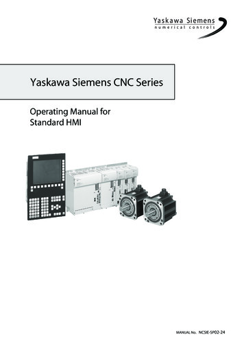
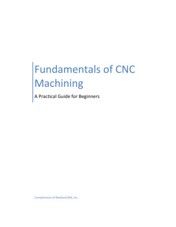
Conversational CNC Programming Example #1Drill Pattern Bolt Circle Variables (G121):X X centerY Y centerR RadiusA Start angle (absolute)N # of holesH # of holes to drill
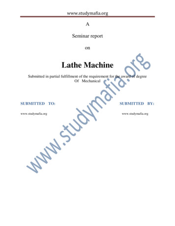
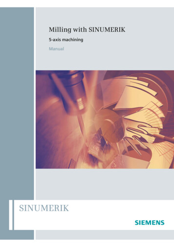
Conversational CNC Programming Example #2Arcs and Lines (dashed line is tool path for 1/8” diameter endmill)
Conversational CNC Programming Example #2 (con’t)Below is the actual tool path code for the previous example. After theuser enters the basic parameters, this is the program that is generated bythe conversational interface to run on the CNC.An analogy to software programming is that conversationalprogramming is similar to programming using a compiler (ie C, Fortran,VB, etc.) and the actual tool path code generated is equivalent to thefinal compiled machine code or instructions.G90 G0 X0 Y-0.75 Z1 F5Z0 M3G1 Z-0.1 E2Y-0.5625G2 J0.5625 X0 Y0.5625G1 X0.6507X1.5625 Y0.03608Y-0.3G2 I-0.2625 X1.3 Y-0.5625G1 X0G0 Y-0.75 Z1M30[G90 absolute; G0 rapid; F XY feed][M3 spindle on, CW][G1 linear motion; E Z feedrate][G2 CW circular motion][G1 linear motion][G2 CW circular motion][G1 linear motion][G0 rapid][M30 end of program/rewind]
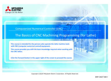
CNC CAM ProgrammingOnce the part has been designed using conventional mechanical designmethods (structural analysis, FEA, fatigue study, etc.), the part ismanufactured using the following method.1. Create a solid 3D model of the part to be produced. Any standardCAD format is acceptable.2. Import the solid model into the CAM (computer aidedmanufacturing) software. (this demonstration uses MasterCAM)3. Input the raw material stock size and set the part’s coordinateorigin.4. Input the necessary information for each tool used in machiningthe part features. Typically, a tool library will exist, which issimply a database of tools and their related parameters.5. For each part feature, select the appropriate tool from the libraryand set the parameters necessary for machining that feature.Typical parameters include spindle speed, depth of cut, feedrate,number of passes, tool path pattern, etc.6. Verify the programmed tool path(s) by running the CAMsoftware’s virtual machining cycle.
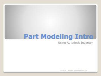
Figure 1. Inventor CAD model of example part (mirrored for clarity).
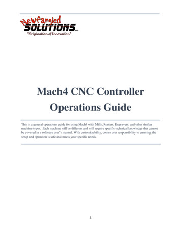
Figure 2. CAM part setup and coordinate zeroing.
Figure 3. Tool library showing database of previously used tools.
Figure 4. Tool parameters stored for each cutting tool used.
Figure 5. CAM parameters for cutting one feature (pocket) in the part.
Figure 6. CAM roughing and finishing parameters.
Figure 7. CAM operations list showing all cutting operations & tools.
Figure 8. Virtual verification cycle used to catch errors before cutting.
Figure 9. Final program ready to be processed by the CNC machine.
Final Facts about CNC Machining CNC manufacturing offers advantages on two types of parts: (1) simple parts that are mass producedand/or (2) complex parts with features requiring multiple axes of simultaneous motion. For simpleparts in low quantity, it is often quicker to produce the parts on manual machines (as in lab). CNC does not inherently imply increased part accuracy. An old CNC with a lot of hours of use willproduce less accurate features than a new quality manual machine and vise-versa; so don’tautomatically associate higher accuracy with CNC machines. (Accuracy has more to do with machinedesign, component selection and mechanical wear.) Modern CNC machines offer increased productivity due to stiffer machine and spindle designs, morepowerful motors, high pressure coolant (up to 1000 psi) that floods the cutting zone, automatic toolchangers, digital workpiece and tool probing, and/or horizontally mounted spindles. Downsides to CNC machines are higher initial cost, larger space and electrical requirements, increasedmaintenance cost, required programming skillset and their inherent complexity means there’s a higherprobably of component failure during the useful lifespan.
CNC Machining . Intro to CNC Machining CNC stands for computer numeric controlled. It refers to any machine tool (i.e. mill, lathe, drill press, etc.) which uses a computer to electronically control the motion of one or more axes on the machine. The development of NC