Transcription
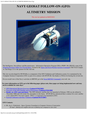
NAVY GEOSAT FOLLOW-ON ALTIMETER MISSION Home PageNAVY GEOSAT FOLLOW-ON (GFO)ALTIMETRY MISSIONThis site last updated on 06/05/2010The Intelligence, Surveillance and Reconnaissance - Information Operations Program Office (PMW-180, ISR-IO) a part of theProgram Executive Office for C4I and Space, located at the Space and Naval Warfare Systems Command's Old Town Campusin San Diego, CA is the sponsor for this web site.This site was developed for SPAWAR as a component of the GFO Validation and Calibration system. It is maintained by theComputer Sciences Corporation (CSC) as part of its contract with SPAWAR. Our thanks to NOAA for hosting the revised site.For an overall view of the Navy's activities in METOC go to the Naval METOC Command's own web site.For more information on GFO, go to the following pages (please note, these pages are being implemented now and maynot be available for some days:GFO Operational Mission Overview (Updated 07/02/2005)Overview of the GFO Satellite and its Performance (Updated 07/02/2005Details on GFO past and future The GFO altimetry satellite that was launched in February 1998 was de-orbited inDecember 2008 and will reenter the atmosphere in the future. SPAWAR has announced that a contract for a new satelliteto be called GFO-2 has been signed. GFO-2 is expected to be launched in 2014.Payload Calibration and Data Validation (Updated 01/27/2007)GFO Contacts:Mr. Jay L. Finkelstein - Space Systems Consultant to Computer Sciences Corporation[E-mail - finkelsj (at) surffirst dot net or finkelsj (at) compuserve dot pcoe/[6/12/14, 3:28:42 PM]
NAVY GEOSAT FOLLOW-ON ALTIMETER MISSION Home PageMr. Morton Rau -- GFO Project Manager at Computer Sciences Corporation[E-mail - mrau4space (at) earthlink dot net]Mr. John Lillibridge -- GFO contact at NOAA[E-mail -- John dot Lillibridge (at) noaa dot gov]Note: If you need to contact the above, please replace the '(at)' and the 'dot' in the email addresses above with an '@' symbol and a period respectively andremove any extraneous spaces. We are trying to prevent automated programs from skimming email addresses from this site.For comments or questions about this Web Site contact Mr. Jay L. Finkelstein at either e-mail /bmpcoe/[6/12/14, 3:28:42 PM]
GFO Mission OverviewGFO Mission OverviewThe GEOSAT Follow-On (GFO) program is the Navy's initiative to develop an operational series of radar altimetersatellites to maintain continuous ocean observation from the GEOSAT Exact Repeat Orbit. GFO is the follow-on to thehighly successful GEOSAT-A and was launched in February 1998.On 29 November 2000 the Navy accepted thesatellite as operational.The Navy GEOSAT MissionThe 5-year GEOSAT mission and its extensive data validation program demonstrated the ability of the radar altimeter tomeasure the dynamic topography of the Western Boundary currents and their associated rings and eddies, to providesea surface height data for assimilation into numerical models, and to map the progression of El Nino in the equatorialPacific. Descriptions of the GEOSAT system characteristics were collected in two special issues of the Johns HopkinsAPL Technical Digest (Ref. 1). Extensive references and collections of ocean science results were presented in specialissues of the Journal of Geophysical Research devoted to GEOSAT (Ref. 2).References:1. Vol. 8, No. 2, April-June 1987; Vol. 10, No. 4, October-December 1989.2. Vol. 95, No. C3, March 15, 1990; Vol. 95, No. C10, October 15, 1990.Program gfo/bmpcoe/Mission/missiona.htm[6/12/14, 3:28:43 PM]
GFO Mission OverviewThe METOC Systems Office of the Space and Naval Warfare Systems Command has overall responsibility forexecuting the procurement and operations of the Navy's environmental sensor satellite.Why GFO , GFO Satellite and Mission Design,---- return to GFO front page pcoe/Mission/missiona.htm[6/12/14, 3:28:43 PM]
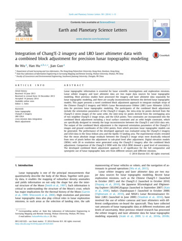
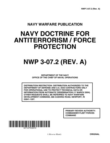
hardwaraGFO Satellite OverviewThis page was last updated on 07/02/05The Navy Prime Contract for the GFO system design, production, and test was awarded by the Space and NavalWarfare Systems Command in August 1992. The system elements included the satellite, payloads, launch vehicle andupdates to the Navy Satellite Ground System.The finished GFO satellite was launched on 10 February 1998, andaccepted on 29 November 2000. The satellite and the ground system are now operational.A summary of the performance to date of the GFO spacecraft on-orbit is posted on the Performance Summary Page.The chart on that page gives an overview of the on-orbit performance of the satellite and with a hyperlink toinformation on any satellite or ground-system anomalies.GFO SpacecraftThe image below shows the spacecraft structure during its Modal Survey and Vibration testingGFO Launch Vehicle - TAURUSThis image shows the expendable launch vehicle on the launch pad at Vandenberg Air ForceBase prior to the 10 February /bmpcoe/Ball hwr/hardwara.htm[6/12/14, 3:28:45 PM]
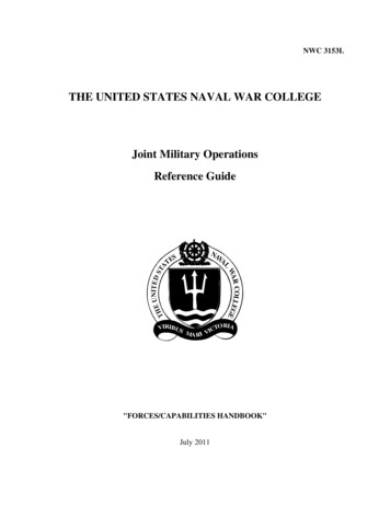
hardwaraGFO RadiometerThis image shows the water vapor microwave radiometer flight unit ready for spacecraft a/gfo/bmpcoe/Ball hwr/hardwara.htm[6/12/14, 3:28:45 PM]
hardwaraGFO AltimeterThis image shows the all solid state microwave radar altimeter flight unit ready for spacecraft integration.GFO SpacecraftThis shows the integrated spacecraft during its system o/bmpcoe/Ball hwr/hardwara.htm[6/12/14, 3:28:45 PM]
hardwara--- return to GFO front page coe/Ball hwr/hardwara.htm[6/12/14, 3:28:45 PM]
exec colProgram and Operations Status ReportUpdated on 01/25/2010The GEOSAT Follow-On satellite altimeter sponsored by the Oceanographer of the Navy was launched 10February 1998. Several difficult problems including confounding interactions between CPU and compilerversions prevented the satellite from running consistently until they were overcome through the intense work anddedication of NAVSOC (The Naval Space Operational Command), the Cal/Val team, Ball Aerospace (the primecontractor for the spacecraft) , in addition to researchers in academia and government laboratories such as theNOAA Laboratory for Satellite Altimetry.The GPS receivers onboard never achieved operational use. Fortunately, NASA had provided a laser retroreflector for the satellite prior to launch and the International Laser Ranging Service (ILRS) provided trackingfrom its global network of laser ranging stations to support the project. Thus high accuracy orbits were providedfor the satellite in addition to the orbit solutions based on the on-board Doppler beacon. (For additional details onILRS, go tohttp://ilrs.gsfc.nasa.gov.) Precise time was provided by synchronizing the drift of the on-board UltraStable Oscillator to NAVSOC ground systems.GFO was accepted by the Navy in 2000. NAVSOC ran the spacecraft during its lifetime, and the data wasprocessed daily at the Naval Oceanographic Office.In summary, there were several critical failures that would have ended the mission before useful data wereprovided if not for the passion and dedication of many individuals and organizations that turned the mission into asuccess.Through the years, GFO performed extremely well thanks to the continued dedication of the people noted above.The data provided by GFO has been used by operational centers to assimilate into numerical prediction systemsthat in both research and operational modes provided critical information such as currents and ocean environmentstructure during many incidents throughout the globe. The data flow was a necessary contributor to movingocean forecasting from the point of a theoretical possibility on which we could conjecture to a soliddemonstration of the feasibility and what the capability can provide and to the point of implementation intooperational forecast centers. It has proved a great success especially since the entire mission was accomplishedon a total budget of 85M. The continued monitoring and careful guidance from NAVSOC, the Cal/Val team,and Ball Aerospace engineers allowed the satellite to outlive its original predicted life of 8 years. Degradation ofbattery capability and attitude control sensitivity to heat excursions brought the satellite system to the point whereit was no longer maintainable. The decision was made to de-orbit the satellite at the end of 2008. All those whocontributed can be proud of what they have achieved.In memoriam, we would also like to remember the contributions of two individuals who helped make the missionsuccessful: Jimmy Mitchell and Vince Noble -- they are no longer with us, but their names are inscribed on aplaque on the satellite.Many of us will keep a little space in our hearts and a little space on our disk drives for the GFO data from "thelittle satellite that could".Added Note: For those who are not part of DoD: All GFO altimetry data was authorized for unconditional (andunclassified) release by SPAWAR. Hence all GFO data (SDRs, GDRs and raw data over some ice areas) wasforwarded to NOAA (and NASA) for distribution and use by the civilian community. NOAA used the SDRsalong with the Medium Laser orbit data from NASA to produce an independent set of GDRs known as theIGDRs. For non-DoD users, NOAA is the formal point of contact for data dissemination. If you are not part ofDoD and wish access to GFO data, please contact John Lillibridge.Future Plans -- the Space and Naval Warfare Systems Command in San Diego intends to launch a new version oe/Exec col/exec col.htm[6/12/14, 3:28:45 PM]
exec colthis satellite to be known as GFO-2. It is expected to be available in 2013.For reference, the nominal GFO satellite ERO orbit parameters are:Semi Major Axis7162.62 Km.Eccentricity0.0008035Inclination108.0448 deg.Argument of Perigee90.5350 deg.--- Return to GFO front page coe/Exec col/exec col.htm[6/12/14, 3:28:45 PM]
Payload Calibration and Data ValidationPayload Calibration and Data ValidationUpdated 07/02/05For information on the SDR and NGDR products go to:Data Product FormatsFor a description of the current GFO timing system go to: System Time ManagementTo delineate the flow of data through the GFO program to those efforts go toData FlowFor a description of the Cal/Val plan and its players, go to the GFO Calibration, Validation and Quality Control Plan(updated 7/02/05)For information on the activities associated with the calibration and validation effort use the buttons/images/hyperlinksbelow.Payload Calibration and Data ValidationOhio State WebSite--- return to GFO front page coe/calval default.htm[6/12/14, 3:28:46 PM]
Why GFO?Why GFO?Navy requirements for geodetic and oceanographic information have been a driving force through the history ofsatellite radar altimetry. The Navy's collection of geodetic information was initially acquired by ship surveys whichwere slow, expensive, and, incomplete. Now, space-borne altimeters provide a more efficient method of collecting thenecessary information to support its environmental predictions and enhance its warfighting capability.Navy applications of GFO will include use of altimeter data in coastal oceanography, in mapping mesoscale fronts andeddies, and, in using basin-scale data for generating eddy-resolving global ocean models. The length and time scales ofthese processes are too large for conventional in-the-water oceanographic instrumentation configurations to measure.Satellite altimetry is the only known method by which oceanographers can precisely measure sea surface topography.The shape of the sea surface is the only physical variable directly measurable from space that is directly and simplyconnected to the large-scale movement of water and the total mass and volume of the ocean.The GFO Mission will support Navy, NOAA, NASA, and University ocean science and ocean monitoring. It isbelieved that ocean circulation may be a major cause of decadal climate change. New scientific evidence indicates thatdramatic, even catastrophic climate changes can occur over the space of only a few years. Recent ice core samplessupport several models where shifts of as much as 10 degrees Celcius occur in as short a time as 3-5 years. Bycomparison, the "little ice age" of 750 years ago resulted from a climate change of only 2 degrees Celsius.Habitable temperatures in the North Atlantic region is due primarily to flow of warmer surface water. As water flowsnorth is becomes more dense and saline through evaporation. Part of the flow sinks and flows south as deep watercurrents. The remainder flows east toward the United Kingdom before turning south as a surface current. Rising globaltemperatures could cause high volumes of melt-water from ice caps to alter the density and salinity in North Atlanticwaters. This might dramatically change the deep and surface circulation of the water leading to drastic climate changesin North America and Europe. NOAA has established the prediction of decadal climate as a major strategic mpcoe/Mission/missionb.htm[6/12/14, 3:28:47 PM]
Why GFO?The measurement performance of the satellite altimeter has been extensively validated. During the Synoptic OceanPrediction (SYNOP) experiment, an aircraft under-flight of a GEOSAT pass dropped Air ExpendableBathythermographs (AXBT's). The rms difference in absolute topography between the altimeter and the AXBT's of 6.8cm when processing the altimeter data with a "synthetic geoid" to provide a precise surface of no motion at mesoscalewavelengths. The GEOSAT data below was provided by o/bmpcoe/Mission/missionb.htm[6/12/14, 3:28:47 PM]
Why GFO?---- more ------- return to GFO front page pcoe/Mission/missionb.htm[6/12/14, 3:28:47 PM]
Spacecraft and Mission DesignThe GFO Spacecraft and Mission DesignThe GFO satellite includes all the capabilities necessary for the precise measurement of bothmesoscale and basin-scale oceanography. A water vapor radiometer has been added to thebasic GEOSAT measurement capability. GFO also included GPS receivers but these are notworking.GFO was launched aboard a TAURUS launch vehicle on 10 February 1998 from VandenbergAir Force Base in California. The launch was near the minimum of the solar cycle. The satellitewas accepted by the Navy on 29 November 2000.During its mission life, the satellite will beretained in the GEOSAT Exact Repeat Mission (ERM) orbit (800 km altitude, 108 degreeinclination, 0.001 eccentricity, and, 100 min period). This 17-day Exact Repeat Orbit (ERO)retraces the ERM ground track to /-1 km. As with the original GEOSAT ERM, the data willbe available for ocean science through NOAA/NOS and NOAA/NESDIS.The 300-kg spacecraft is approximately 3-m long and supports the following payloads:1. Radar Altimeter - single frequency (13.5 GHz) with 3.5-cm height precision.2. Water Vapor Radiometer - dual frequency (22 and 37 GHz) nadir-looking with a pathcorrection accuracy of 1.9 cm rms.3. GPS Receivers – Not working4. Doppler Beacon - GEOSAT performance-stable oscillators and doppler beacons willallow operational orbits to be determined with 1.8-cm rms radial orbit error for mesoscaleoceanography (after tilt and bias removal along a 3000-km arc-filter length.The payloads will feature complete redundancy, light weight (47 kg total), and low powerconsumption (121 W /bmpcoe/Mission/missiond.htm[6/12/14, 3:28:48 PM]
Spacecraft and Mission Design---- more pcoe/Mission/missiond.htm[6/12/14, 3:28:48 PM]
SATELLITE PERFORMANCE SUMMARYSATELLITE PERFORMANCE SUMMARY FOR 2005FOR THE CURRENT 17 DAY CYCLESUpdated07/02/05BACKGROUNDThe Navy is tracking the performance of the satellite since it was accepted on 29 November 2000. The first 17-day Cycle afteracceptance by the Navy isnumbered 000 and is used as a reference for the succeeding cycles.The 17-day Cycle which startedon December 16, 2000 (Julian day 352) is the beginning of the first evaluation cycle, Cycle 001, which ended on 2 January2001 (Julian day 2001 002). Each subsequent 17 day cycle is consecutively numbered.The Navy is also tracking any systemanomalies such as component failures, required use of redundant systems, and existence of permanent/intermittent lossconditions. The results are shown on the System Anomaly page (Updated 07/02/05)Performance of the satellite and its sensors is tracked by four effectiveness measures, Coverage, Tracking System Precision,Radar Altimeter (RA) Precision, and Water Vapor Radar (WVR) Precision. These measures are calculated as follows:Coverage -- The coverage is determined for each 17-day cycle by a summation of the over water crossover points in theNAVY Geophysical Data Records (NGDRs) that corresponded to Sensor Data Records (SDRs) from the Ball providedPOC which have the altimeter in fine track and which are not flagged as bad (missing, incomplete, out-of-range, etc) forboth the ascending and descending arcs. The result is compared with the maximum possible number of over watercrossovers. The ratio of these two numbers expressed as a percentage is the measure of system coverage.Tracking System Precision - The precision of the tracking system is determined by computing the global mean square ofthe altimeter crossover residuals for a 17-day cycle. The Tracking System Precision is defined as the mesoscalecomponent of this (predominantly) long wavelength error. Although originally applied only to the Doppler system, withthe failure of the GPS on-board receivers and the reliance on the medium quality laser generated orbits, this measure isnow being applied to the MOE data.Radar Altimeter Precision - The altimeter precision is determined as the high frequency limit of the altimeter noisespectrum using collinear track differences. The result is reported as the world-wide equivalent white noise standarddeviation on the 1 second average ranges. The procedure includes editing of isolated noise spikes and avoidance ofareas with high significant wave height.Water Vapor Radiometer Precision - The radiometer precision (radiometer white noise) is determined in the same manneras the altimeter precision with power spectra derived from multiple individual tracks rather than collinear trackdifferences. The result is calculated as the world-wide equivalent white noise standard deviation on the 1 secondsamples of integrated atmospheric water vapor in kg/sq m and converted to the corresponding white noise standarddeviation on the path length in cm ( 0.16 kg/sq m is equivalent to 0.1 cm). This procedure includes editing of areas overland and ice and areas of heavy rainfall.PERFORMANCE TO DATEPERFORMANCE SUMMARYCycleNumberJulian DaysCoverage(%)08108208308408508604 251 - 04 26704 268 - 04 28404 285 - 04 30104 302 - 04 31804 319 - 04 33504 336 - 04 sod/lsa/gfo/bmpcoe/Exec col/satellite performance summary.htm[6/12/14, 3:29:48 20.121Notes3940
SATELLITE PERFORMANCE SUMMARY08708808909009109204 353 - 05 00305 004 - 05 02005 021 - 05 03705 038 - 05 05405 055 - 05 07105 072 - 05 0.12041FOR THE PERFORMANCE OF CYCLES 001 to 020, click hereFOR THE PERFORMANCE OF CYCLES 021 to 040, click hereFOR THE PERFORMANCE OF CYCLES 041 to 060, click hereFOR THE PERFORMANCE OF CYCLES 061 to 080, click hereExplanatory Notes029 - The results for cycle 060 and 061 reflect the fact that the satellite was in its sun-pointing mode with all payloads off forthese two cycles. Hence there is no coverage and the other performance measures are undefined.030 - The coverage result for cycle 062 reflects the fact that the satellite was in its sun-pointing mode with the payloads off forthe first day of this cycle (as a continuation of the above event). This reduced the coverage slightly but did not affect theremaining indices.031 - The coverage result for cycle 064 reflects the fact that the satellite was in its sun-pointing mode with the payloads off for alittle over about three days of this cycle (from about 2218Z on day 336 until about 1736Z on day 340). This reduced thecoverage but did not affect the remaining indices.032 - The raw coverage for cycle 065 was 76.2% which reflects that the satellite was coming out of its sun pointing mode forthe first few days of this cycle. The number shown includes an allowance for ground system losses.033 - The raw coverage for cycle 068 was 90.3%, however an allowance for ground system losses increases the value to 95.3%.034 - The coverage result for cycle 069 reflects the fact that the satellite was in its sun-pointing mode with the payloads off forthe last several days of this cycle to avoid thermal issues with the attitude control wheels. This reduced the coverage but didnot affect the remaining indices.035- The results for cycle 070 and 071 reflect the fact that the satellite was in its sun-pointing mode with all payloads off forthese two cycles and into the beginning of cycle 072. Hence there is no coverage and the other performance measures areundefined.036 - The raw coverage for cycle 072 was 64.0% since the payloads were off during the first few days of the cycle, however anallowance for ground system losses increases the value to 64.1%037 - The raw coverage for cycle 074 was 93.2%, however an allowance for ground system losses increases the value to 94.8%.038 - The raw coverage for cycle 077 was 94.1%, however an allowance for ground system losses increases the value to 94.2%039 - The results for cycle 079, 080 and 081 reflect the fact that the WVR payload was off during the last few days of cycle 79,all of cycle 80 and the beginning of cycle 81 to avoid thermal issues with the attitude control wheels. The indices shown(including coverage) are only for the period when the WVR was on.040 - The raw coverage for cycle 086 was 94.8%, however an allowance for ground system losses increases the value to 95.0%041 - The coverage result for cycle 088 reflects the fact that the satellite was in its sun-pointing mode with the payloads off for aabout 29 hours of this cycle (about 9 hours at the end of day 05 018 and about 20 hours on day 05 019) due to an attitudecontrol anomaly. This reduced the coverage but did not affect the remaining o/bmpcoe/Exec col/satellite performance summary.htm[6/12/14, 3:29:48 PM]
System Time ManagementSYSTEM TIME MANAGEMENTGEOSAT TIME MANAGEMENTThe GFO satellite outputs a measure of time onboard the satellite as part of Doppler beacon payload. The onboardsatellite time is corrected on the ground to yield an altimeter measurement time for the GFO in a manner similar to theoriginal GEOSAT which utilized a Time Management Unit (TMU) in the APL/JHU ground station.THE TIME MANAGEMENT "Ratio" PARAMETERThe Doppler Beacon stable oscillator provides the frequency reference for the altimeter and the Vehicle Time CodeWord (VTCW) that is used to time tag the data. The frequency of this oscillator and therefore the VTCW clock rate(nominally 1E6 ticks/sec) were initially offset 80 ppm from its nominal value but have drifted with respect to thisnominal offset throughout the mission.The GFO ground system tracks the drift in the stable oscillator offset by measuring the drift in the VTCW. A "Ratio"parameter is defined as the VTCW tick interval, the number of seconds per VTCW tick:Ratio sec/tick 1 sec / (1E6 ticks * (1 oscillator offset))The initial factory setting produces:Ratio 1 / (1E6 * (1 80E-6)) 0.99992E-6 sec/tickThe nominal altimeter timing intervals e.g., the 980 microsecond intervals between measurements, are stated at thenominal clock frequency. The real clock is running faster and so the interval must be reduced by the same (nominally)80 ppm:real interval nominal interval / (1 80E-6) secor because of the drift measured by the ratio parameter above, the interval is given exactly by:measured interval nominal interval * Ratio * 1E6 secTIME BIASThe parameter Time Bias (initial), included as field 18 in the SDR header, is provided to allow GDR producers andCal/Val SDR file users to correct time. The bias is a measured parameter, determined from crossovers and collineardifferences. (Note: If this bias is given in satellite time then it must be translated to ground [real] time by ratio*1E6 asshown above. For this and succeeding sections it is assumed that field 18 is already in real [ground] time.) The bias isapplied to data product times as detailed in the following sections. The bias is multiplied by Ratio*1.0E6 in order toaccount for the offset of the VTCW clock as described in the previous section.Each Cal/Val file record is labeled with one UTC word, call it UTC CalVal. The user should apply the time bias as:UTC CalVal Biased UTC CalVal - Time Bias /bmpcoe/Data val/Cal formats/time mgt.htm[6/12/14, 3:31:00 PM]
System Time ManagementSDR TIMEEach SDR record is labeled with one Universal Time Code (UTC) word, call it UTC SDR. The record contains 10height words, H[0], ., H[9]. UTC SDR is the time of H[0], corrected for instrument effects, that is, UTC SDR is thetime the satellite is at height H[0]. As derived above, the 10/sec measurement interval is: 0.0980 * Ratio * 1.0E6seconds, where Ratio (included as field 25 in the SDR Header) accounts for the measured offset of the spacecraftVehicle Time Code Word (VTCW) from its nominal frequency, 1 MHz.Time Bias (initial), included as SDR header field 18, must be applied by the user:UTC SDR Biased UTC SDR - Time Bias initialThe measurement time of height word H[i], call it UTC H[i] is:UTC H[i] UTC SDR Biased (i*0.0980*Ratio*1.0E6) secondsfor i 0, .,9.Any record can be time tagged by computing the number of seconds from the time epoch to the beginning of the SDRday (SDR Header field 5) and adding it to the biased record UTC time (time in seconds since midnight).NGDR TIMEEach NGDR record is labeled with one UTC, call it UTC NGDR. The record contains one Sea Surface H - Uncorrectedheight word, derived from the 10 SDR height words by averaging and applying instrument level corrections. These 10height words are separated by 9 intervals so the measurement time of this word is determined from the correspondingSDR time as:UTC NGDR UTC SDR (4.5*0.0980)*Ratio*1.0E6 - Time Bias initial.(Note: By convention the time of the SSH-height word is taken to be the time of the midpoint of the 9 SDR height wordintervals.)SPACECRAFT TO SDR TIME MANAGEMENTa) VTCW Timing ReferenceThe Vehicle Time Code Word (VTCW) is the key element of all critical timing functions performed on the GFOspacecraft. The VTCW is a 48 bit ripple counter that is driven by the ultra-stable oscillator in the Doppler Beacon thatalso drives the altimeter. The VTCW system includes circuits that allow multiple software functions (users) to latch andread the current value of the VTCW. The VTCW is a counter, not a clock.b) Altimeter Time TagWhen the altimeter outputs a data packet, the VTCW is latched on the leading edge of the "enable" signal, and isappended to the altimeter data.d) Generating The Spacecraft Clock Correlation FileSoftware at NAVSOC operates on the telemetry packets and correlates the VTCW counter with UTC (derived from aground based GPS Receiver). A Spacecraft Clock Correlation file (SCC.dat) is generated that provides the slope coe/Data val/Cal formats/time mgt.htm[6/12/14, 3:31:00 PM]
System Time Managementoffset needed to convert VTCW to UTC. The file is transmitted to the POCC for SDR generation.Conceptually, given two UTC times and two corresponding VTCW counter values from the GPS telemetry data, onecan determine the ratio derived above as a linear fit:Ratio (UTC 2 - UTC 1) / (VTCW 2 - VTCW 1) in UTC sec/VTCW ticksThe SCC.dat file generated contains the Ratio and one UTC SCC, VTCW SCC pair, allowing the UTC time for anyVTCW to be determined:UTC (Ratio * (VTCW-VTCW SCC) UTC SCC) secThe SCC.dat data used for generating the SDR are included in the SDR Header. For example, a day 98073 SDR Headerwould have parameters:UTC year (field 20) 1998UTC doy (field 21) 073UTC sec (field 23) 81053.126000VTCW (field 24) 742452500.00Ratio (field 25) 9.9992E-7Note that the above Ratio reflects exactly the factory value, the field would have the actual value.The NAVSOC software implementation for the SCC.dat generation uses a circular file that can hold a maximum of43,997 UTC/VTCW pairs. Ratio is determined by a linear fit to the available points corrected for telemetry noise. Aminimum of three points is required. The earliest VTCW/UTC pair is included in the SCC.dat file and is the base timein this file.e) Altimeter Range From Time DelayThe GFO altimeter tracks the radar time delay, tau, with a closed loop adaptive algorithm. If the altimeter transmitted apulse and waited for the return from the surface, the resulting surface time delay, call it tau surface, would be a directmeasure of the range to the surface. In order to increase the ocean sampling rate and reduce height noise, the radar hasfive pulses in the air at any time
with a hyperlink to. information on any satellite or ground-system anomalies. GFO Spacecraft. The image below shows the spacecraft structure during its Modal Survey and Vibration testing GFO Launch Vehicle - TAURUS This image shows the expendable launch vehicle on the launch pad at Vandenberg Air Force Base prior to the 10 February launch.