Transcription
ELECTRIC DRYER INSTALLATION INSTRUCTIONS29" WIDE MODELS - U.S.A. ONLYPara obtener acceso al manual de uso y cuidado en español, o para obtener información adicional acerca de su producto, visite:www.whirlpool.comTenga listo su número de modelo completo. Puede encontrar el número de modelo y de serie dentro de la cavidad superior de la puerta.Table of ContentsDRYER SAFETY . 2INSTALLATION REQUIREMENTS . 4Tools and Parts . 4Location Requirements . 5Electrical Requirements . 6Install Leveling Legs . 7Electrical Connection . 7VENTING. 13Venting Requirements . 13Plan Vent System . 14Venting Kits . 14Install Vent System . 16Connect Vent . 16Level Dryer . 16Complete Installation Checklist . 16Reverse Door Swing (Optional) . 17Troubleshooting . 19W10514172BW10514174A-SP
DRYER SAFETY2
3
INSTALLATION REQUIREMENTSTools and PartsGather the required tools and parts before starting installation.Read and follow the instructions provided with any tools listed here.Tools needed:LevelCaulking gun andcompound (for installingnew exhaust vent)Parts supplied (all models):Flat-blade screwdriver#2 Phillips screwdriverLeveling legs (4)Wire stripper(direct wire installations)Tin snips(new vent installations)Parts package is located in dryer drum. Check that all partsare included.Parts needed:Check local codes. Check existing electrical supply and venting,and read “Electrical Requirements” and “Venting Requirements”before purchasing parts.Mobile home installations require metal exhaust system hardware,available for purchase from the dealer from whom you purchasedyour dryer. For further information, please reference the“Assistance or Service” section of the “Use and Care Guide”.1/4" nut driver(recommended)Vent clampsIf using a power supply cord:Use a UL listed power supply cord kit marked for use withclothes dryers. The kit should contain: A UL listed 30-amp power supply cord, rated 120/240 voltminimum. The cord should be type SRD or SRDT and beat least 4 ft. (1.22 m) long. The wires that connect to thedryer must end in ring terminals or spade terminals withupturned ends. A UL listed strain relief.Adjustable wrench thatopens to 1" (25 mm) orhex-head socket wrenchUtility knifeTape measurePliers4
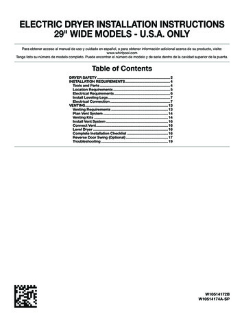
Location RequirementsMinimum spacing for recessed area or closetinstallationThe dimensions shown following are for the minimum spacingallowed. Additional spacing should be considered for ease ofinstallation and servicing. Additional clearances might be required for wall, door, andfloor moldings. Additional spacing of 1" (25 mm) on all sides of the dryeris recommended to reduce noise transfer. For closet installation, with a door, minimum ventilationopenings in the top and bottom of the door are required.Louvered doors with equivalent ventilation openingsare acceptable. Companion appliance spacing should also be considered.Minimum Required SpacingYou will need: A location allowing for proper exhaust installation.See “Venting Requirements.” A separate 30 amp circuit. If you are using power supply cord, a grounded electricaloutlet located within 2 ft. (610 mm) of either side of dryer.See “Electrical Requirements.” A sturdy floor to support the total weight (dryer and load)of 200 lbs. (90.7 kg). The combined weight of a companionappliance should also be considered. Level floor with maximum slope of 1" (25 mm) under entiredryer. (If slope is greater than 1" [25 mm], install ExtendedDryer Feet Kit, Part Number 279810.) If not level, clothesmay not tumble properly and automatic sensor cycles maynot operate correctly.Do not operate your dryer at temperatures below 45 F (7 C). Atlower temperatures, the dryer might not shut off at the end of anautomatic cycle. Drying times can be extended.The dryer must not be installed or stored in an area where it willbe exposed to water and/or weather.Check code requirements. Some codes limit, or do not permit,installation of the dryer in garages, closets, mobile homes, orsleeping quarters. Contact your local building inspector.Installation clearances:The location must be large enough to allow the dryer door toopen fully.14" max.*(356 mm)18"*(457 mm)3"*(76 mm)48 in.2*2(310 cm )24 in.2 * 2(155 cm )1"(25 mm)29"(737 mm)A1"* 27¾"1"(25 mm) (25 mm) (705 mm)B3"*(76 mm)CA. Recessed areaB. Side view - closet or confined areaC. Closet door with vents*Additional spacing recommendedMobile home - Additional installation requirementsThis dryer is suitable for mobile home installations. Theinstallation must conform to the Manufactured HomeConstruction and Safety Standard, Title 24 CFR, Part 3280(formerly the Federal Standard for Mobile Home Constructionand Safety, Title 24, HUD Part 280). Metal exhaust system hardware, which is available forpurchase from your dealer. Special provisions must be made in mobile homes tointroduce outside air into the dryer. The opening (suchas a nearby window) should be at least twice as largeas the dryer exhaust opening.Dryer DimensionsABA. Wide opening side-swing doorB. Wide opening hamper door*Most installations require a minimum 5½" (140 mm) clearancebehind the dryer for the exhaust vent with elbow. See “VentingRequirements.”5
Electrical RequirementsIt is your responsibility: To contact a qualified electrical installer. To be sure that the electrical connection is adequate and inconformance with the National Electrical Code, ANSI/NFPA70-latest edition and all local codes and ordinances.The National Electrical Code requires a 4-wire power supplyconnection for homes built after 1996, dryer circuits involvedin remodeling after 1996, and all mobile home installations.A copy of the above code standards can be obtained from:National Fire Protection Association, One Batterymarch Park,Quincy, MA 02269. To supply the required 3 or 4 wire, single phase, 120/240 volt,60 Hz, AC only electrical supply (or 3 or 4 wire, 120/208 voltelectrical supply, if specified on the serial/rating plate) on aseparate 30-amp circuit, fused on both sides of the line. Atime-delay fuse or circuit breaker is recommended. Connectto an individual branch circuit. Do not have a fuse in theneutral or grounding circuit. Do not use an extension cord. If codes permit and a separate ground wire is used, it isrecommended that a qualified electrician determine that theground path is adequate.Electrical ConnectionTo properly install your dryer, you must determine the type ofelectrical connection you will be using and follow the instructionsprovided for it here. If local codes do not permit the connection of a neutralground wire to the neutral wire, see “Optional 3-wireconnection” section. This dryer is manufactured ready to install with a 3-wireelectrical supply connection. The neutral ground wire ispermanently connected to the neutral conductor (white wire)within the dryer. If the dryer is installed with a 4-wire electricalsupply connection, the neutral ground wire must be removedfrom the external ground connector screw (green screw), andsecured under the neutral terminal (center or white wire) ofthe terminal block. When the neutral ground wire is securedunder the neutral terminal (center or white wire) of the terminalblock, the dryer cabinet is isolated from the neutral conductor. A 4-wire power supply connection must be used when thedryer is installed in a location where grounding through theneutral conductor is prohibited. Grounding through the neutralis prohibited for (1) new branch-circuit installations, (2) mobilehomes, (3) recreational vehicles, and (4) areas where localcodes prohibit grounding through the neutral conductors.If using a power supply cord:Use a UL listed power supply cord kit marked for use withclothes dryers. The kit should contain: A UL listed 30-amp power supply cord, rated 120/240 voltminimum. The cord should be type SRD or SRDT and beat least 4 ft. (1.22 m) long. The wires that connect to thedryer must end in ring terminals or spade terminals withupturned ends. A UL listed strain relief.6If your outlet looks like this:Then choose a 4-wire power supply cord withring or spade terminals and UL listed strainrelief. The 4-wire power supply cord, at least4 ft. (1.22 m) long, must have 4 10-gauge solidcopper wires and match a 4-wire receptacle ofNEMA Type 14-30 R. The ground wire (ground4-wire receptacle conductor) may be either green or bare. The(14-30R)neutral conductor must be identified by a whitecover.If your outlet looks like this:Then choose a 3-wire power supply cord withring or spade terminals and UL listed strainrelief. The 3-wire power supply cord, at least4 ft. (1.22 m) long, must have 3 10-gauge solidcopper wires and match a 3-wire receptacle of3-wire receptacle NEMA Type 10-30R.(10-30R)If connecting by direct wire:Power supply cable must match power supply (4-wire or 3-wire)and be: Flexible armored cable or nonmetallic sheathed copper cable(with ground wire), covered with flexible metallic conduit. Allcurrent-carrying wires must be insulated. 10-gauge solid copper wire (do not use aluminum). At least 5 ft. (1.52 m) long.
Install Leveling LegsElectrical ConnectionPower Supply Cord1.Prepare dryer for leveling legsTo avoid damaging floor, use a large flat piece of cardboardfrom dryer carton; place under entire back edge of dryer.Firmly grasp dryer body (not console panel) and gently laydryer down on cardboard.2.Electrical Connection OptionsScrew in leveling legsdiamondmarkingExamine leveling legs, find diamond marking. Screw legs intoleg holes by hand, use a wrench to finish turning legs untildiamond marking is no longer visible.Now stand the dryer on its feet. Slide the dryer until it isclose to its final location. Leave enough room for electricalconnection and to connect the exhaust vent.1. Choose electrical connection typePower supply cord 4-wire receptacle(NEMA Type 14-30R): Go to steps 1-2 onpage 9 for power supply cord strain relief:then steps 3-6 for 4-wire Power SupplyCord Connection section. Then, go toVenting Requirements.Power supply cord 3-wire receptacle(NEMA Type 10-30R): Go to steps 1-2 onpage 9 for power supply cord strain relief:then steps 3-5 for 3-wire Power SupplyCord Connection section.Then go to Venting Requirements.4-wire direct connection: Go to steps1-2 on page 10 for direct wire strain relief:then steps 3-8 for 4-wire Direct WireConnection section. Then go to VentingRequirements.3-wire direct connection: Go to steps1-2 on page 11 for direct wire strain relief:then steps 3-7 for 3-wire Direct WireConnection section. Then go to VentingRequirements.NOTE: If local codes do not permit connection of acabinet-ground conductor to neutral wire, go to “Optional3-wire Connection” section. This connection may beused with either a power supply cord or a direct wireconnection.7
Direct WirePower Supply Cord ConnectionPower supply cord strain relief1.Attach power supply cordstrain reliefABCDRemove the screws from a 3/4" (19 mm) UL listed strain relief(UL marking on strain relief). Put the tabs of the two clampsections (C) into the hole (B) below the terminal block openingso that one tab is pointing up (A) and the other is pointingdown (D), and hold in place. Tighten strain relief screws justenough to hold the two clamp sections (C) together.2.Attach power supply cordto strain relief2. Remove terminal block coverB CDAPut power supply cord through the strain relief. Be sure thatthe wire insulation on the power supply cord is inside thestrain relief. The strain relief should have a tight fit with thedryer cabinet and be in a horizontal position. Do not furthertighten strain relief screws at this point.EFBefore you start, disconnect power. Remove hold-down screw(D) and terminal block cover (A).A. Terminal block coverB. External ground conductor screwC. Center terminal block screwD. Hold-down screwE. Neutral ground wireF. Hole below terminal block cover8For 3-wire Power Supply Cord Connection, see page 9.For 4 wire Power Supply Cord Connection, continue tostep 3.
4-wire Power Supply Cord Connection5. Connect ground wireIMPORTANT: A 4-wire connection is required for mobilehomes and where local codes do not permit the use of 3-wireconnections.BACA.B.C.D.E.F.G.3.AFEDG4-wire receptacle (NEMA type 14-30R)4-prong plugGround prongNeutral prongSpade terminals with upturned ends3/4" (19 mm) UL listed strain reliefRing terminalsPrepare to connect neutralground wire and neutral wire.FConnect ground wire (F) (green or bare) of power supply cordto external ground conductor screw (A). Tighten screw.6. Connect remaining wiresABERemove center terminal block screw (B). Remove neutralground wire (E) from external ground conductor screw (A).4.Connect neutral ground wireand neutral wireCConnect remaining wires to outer terminal block screws.Tighten screws. Finally, reinsert tab of terminal block coverinto slot of dryer rear panel. Secure cover with hold-downscrew. Now, go to Venting Requirements.3-wire Power Supply Cord ConnectionUse where local codes permit connecting cabinet-groundconductor to neutral wire.BCA.B.C.D.E.F.G.Connect neutral ground wire (E) and neutral wire (white orcenter) (C) of power supply cord under center terminal blockscrew (B). Tighten screw.EABEDG3-wire receptacle (NEMA type 10-30R)3-wire plugNeutral prongSpade terminals with upturned ends3/4" (19 mm) UL listed strain reliefRing terminalsNeutral (white or center wire)F3. Remove center screwBRemove center terminal block screw (B).9
2. Attach direct wire cable to4. Connect neutral wireBstrain reliefCConnect neutral wire (white or center) (C) of power supply cordto center terminal block screw (B). Tighten screw.5. Connect remaining wiresPut direct wire cable through the strain relief. The strain reliefshould have a tight fit with the dryer cabinet and be in ahorizontal position. Tighten strain relief screws.For 3-wire Direct Wire Connection, see page 11.For 4 wire Direct Wire Connection, continue to step 3 below.4-wire Direct Wire ConnectionIMPORTANT: A 4-wire connection is required for mobile homesand where local codes do not permit 3-wire connections.3. Prepare your 4-wire cable fordirect connectionConnect remaining wires to outer terminal block screws.Tighten screws. Finally, reinsert tab of terminal block cover intoslot of dryer rear panel. Secure cover with hold-down screw.Now, go to Venting Requirements.Direct Wire ConnectionDirect wire strain relief1. Attach direct wire strain reliefABCUnscrew the removable conduit connector (A) and any screwsfrom a 3/4" (19 mm) UL listed strain relief (UL marking on strainrelief). Put the threaded section of the strain relief through thehole (B) below the terminal block opening. Reaching inside theterminal block opening, screw the removable conduit connectoronto the strain relief threads (C).101"m)(25 m5(127 "mm)Direct wire cable must have 5 ft. (1.52 m) of extra length so dryermay be moved if needed.Strip 5" (127 mm) of outer covering from end of cable, leavingbare ground wire at 5" (127 mm). Cut 11/2" (38 mm) fromremaining 3 wires. Strip insulation back 1" (25 mm). Shape endsof wires into hooks.4. Connect wires to terminal blockTo connect wires to terminal block, place hooked end of wireunder terminal block screw, facing to the right, squeeze hookedend together and tighten screw.
5. Prepare to connect neutralground wire and neutral wire8. Connect remaining wiresABERemove center terminal block screw (B). Remove neutralground wire (E) from external ground conductor screw (A).6. Connect neutral ground wireand neutral wirePlace hooked ends of remaining direct wire cable wires underouter terminal block screws (hooks facing right). Squeeze hookedends together and tighten screws. Finally, reinsert tab of terminalblock cover into slot of dryer rear panel. Secure cover with holddown screw. Now, go to Venting Requirements.3-wire Direct Wire ConnectionUse where local codes permit connecting cabinet-groundconductor to neutral wire.3. Prepare your 3-wire cable fordirect connection1"m)52( mCB3½"(89 mm)EConnect neutral ground wire (E) and place hooked end (hookfacing right) of neutral wire (white or center wire) (C) of directwire cable under center screw of terminal block (B). Squeezehooked ends together and tighten screw.7. Connect ground wireDirect wire cable must have 5 ft. (1.52 m) of extra length sodryer may be moved if needed.Strip 31/2" (89 mm) of outer covering from end of cable. Stripinsulation back 1" (25 mm). If using 3-wire cable with groundwire, cut bare wire even with outer covering. Shape wire endsinto hooks.4. Connect wires to terminal blockATo connect wires to terminal block, place hooked end of wireunder terminal block screw, facing to the right, squeeze hookedend together and tighten screw.5. Remove center screwFConnect ground wire (green or bare) (F) of direct wire cableto external ground conductor screw (A). Tighten screw.BRemove center terminal block screw (B).11
2. Connect neutral ground wire6. Connect neutral wireand neutral wireBBCCPlace hooked end of neutral wire (white or center) (C) of directwire cable under center terminal block screw (B). Squeezehooked end together. Tighten screw.EConnect neutral ground wire (E) and neutral wire (white orcenter wire) (C) of power supply cord or cable under centerterminal block screw (B). Tighten screw.7. Connect remaining wires3. Connect remaining wiresPlace hooked ends of remaining direct wire cable wires underouter terminal block screws (hooks facing right). Squeeze hookedends together and tighten screws. Finally, reinsert tab of terminalblock cover into slot of dryer rear panel. Secure cover with holddown screw. Now, go to Venting Requirements.Optional 3-wire ConnectionYou must verify with a qualified electrician that thisgrounding method is acceptable before connecting.1. Prepare to connect neutralPlace hooked ends of remaining wires under outer terminalblock screws (hooks facing right). Tighten screws.4. Connect external ground wireAground wire and neutral wireABERemove center terminal block screw (B). Remove neutral groundwire (E) from external ground conductor screw (A).12GConnect a separate copper ground wire (G) from the externalground conductor screw (A) to an adequate ground. Finally,reinsert tab of terminal block cover into slot of dryer rearpanel. Secure cover with hold-down screw. Now, go to VentingRequirements.
VENTINGVenting RequirementsExhaust hoods: Must be at least 12" (305 mm) from ground or any object thatmay obstruct exhaust (such as flowers, rocks, bushes, orsnow).Recommended Styles:Louvered hoodBox hoodAcceptable Style:WARNING: To reduce the risk of fire, this dryer MUST BEEXHAUSTED OUTDOORS.IMPORTANT: Observe all governing codes and ordinances.Dryer exhaust must not be connected into any gas vent,chimney, wall, ceiling, attic, crawlspace, or a concealed spaceof a building. Only rigid or flexible metal vent shall be used forexhausting.Angled hoodElbows: 45 elbows provide better airflow than 90 elbows.Good4"(102 mm)Better4" (102 mm) heavy metal exhaust vent Only a 4" (102 mm) heavy metal exhaust vent and clampsmay be used. Do not use plastic or metal foil vent.Rigid metal vent: Recommended for best drying performance and to avoidcrushing and kinking.Flexible metal vent: (Acceptable only if accessible to clean) Must be fully extended and supported in final dryer location.Clamps: Use clamps to seal all joints. Exhaust vent must not be connected or secured with screwsor other fastening devices that extend into interior of ductand catch lint. Do not use duct tape. Remove excess to avoid sagging and kinking that may resultin reduced airflow and poor performance. Do not install in enclosed walls, ceilings, or floors. The total length should not exceed 73/4 ft. (2.4 m).NOTE: If using an existing vent system, clean lint from entirelength of the system and make sure exhaust hood is notplugged with lint. Replace plastic or metal foil vents with rigidmetal or flexible metal vents. Review “Vent System Chart” and,if necessary, modify existing vent system to achieve best dryingperformance.See “Venting Kits” for more information.13
Alternate installations for close clearancesPlan Vent SystemVenting systems come in many varieties. Select the type bestfor your installation. Two close-clearance installations are shown.Refer to the manufacturer’s instructions.Recommended exhaust installationsTypical installations vent the dryer from the rear of the dryer.Other installations are possible.BCDEFAGBOver-The-Top installation (also available with one offset elbow)HA.B.C.D.DryerElbowWallExhaust hoodE.F.G.H.ClampsRigid metal or flexible metal ventVent length necessary to connect elbowsExhaust outletPeriscope installationNOTE: The following kits for close clearance alternateinstallations are available for purchase.Venting KitsFor more information, call 1-866-698-2538, or visit usat www.whirlpool.com/accessories.Part Number Descriptions148171587RP0–5" Metal vent periscope4396037RP0"-18" Metal vent periscope4396011RP18" - 29" Metal vent periscope439601429" - 50" Metal vent periscope4392892In-Wall metal DuraVent Periscope4396028Sure Connect venting kit(over-the-top installation)4396009RP5' Universal connect vent, flexible dryer venting4396010RP6' SecureConnect vent, flexible dryer venting4396013RBDryer vent installer’s kit4396033RP5' flexible dryer venting with clamps4396727RP8' flexible dryer venting with clamps4396004Dryer offset elbow4396005Wall offset elbow4396006RWDuraSafe close elbow4396007RWThrough-the-wall vent cap4396008RP4" steel dryer venting clamps - 2 pack8212662Flush mounting louvered vent hood 4"
Special provisions for mobile home installations:The exhaust vent must be securely fastened to a noncombustibleportion of the mobile home structure and must not terminatebeneath the mobile home. Terminate the exhaust vent outside.Determine vent path: Select route that will provide straightest and most directVent System Chart(Long Vent Models Only)Number of90 turnsor elbowsTypeof ventBox/louvered, orAngled hoods0Rigid metal120 ft. (36.6 m)1Rigid metal110 ft. (33.5 m)2Rigid metal100 ft. (30.5 m)3Rigid metal90 ft. (27.4 m)4Rigid metal80 ft. (24.4 m)5Rigid metal70 ft. (21.3 m)path outdoors. Plan installation to use fewest number of elbows and turns. When using elbows or making turns, allow as much roomas possible.Install Vent System1. Install exhaust hood Bend vent gradually to avoid kinking. Use as few 90 turns as possible.Determine vent length and elbows needed for bestdrying performance:12" min.(305 mm) Use following Vent system chart to determine type of ventmaterial and hood combinations acceptable to use.NOTE: Do not use vent runs longer than those specifiedin Vent system chart. Exhaust systems longer than thosespecified will: Shorten life of dryer.12" min.(305 mm) Reduce performance, resulting in longer drying timesand increased energy usage.The Vent system chart provides venting requirements that willhelp achieve best drying performance.Vent System ChartNumber of90 turnsor elbowsTypeof ventBox/louveredhoodsAngledhoods0Rigid metal64 ft. (20 m)58 ft. (17.7 m)1Rigid metal54 ft. (16.5 m)48 ft. (14.6 m)2Rigid metal44 ft. (13.4 m)38 ft. (11.6 m)3Rigid metal35 ft. (10.7 m)29 ft. (8.8 m)4Rigid metal27 ft. (8.2 m)21 ft. (6.4 m)Install exhaust hood and use caulking compound to sealexterior wall opening around exhaust hood.2. Connect vent to exhaust hoodVent must fit over the exhaust hood. Secure vent to exhausthood with 4" (102 mm) clamp. Run vent to dryer locationusing straightest path possible. Avoid 90 turns. Use clampsto seal all joints. Do not use duct tape, screws, or otherfastening devices that extend into interior of vent to securevent, because they can catch lint.15
Connect VentNOTE: The dryer must be level for the moisture sensing systemto operate correctly.1. Connect vent to exhaust outletNot LevelLEVELNot Level2. Tighten and adjust leveling legsUsing a 4" (102 mm) clamp, connect vent to exhaust outletin dryer. If connecting to existing vent, make sure vent isclean. Dryer vent must fit over dryer exhaust outlet and insideexhaust hood. Check that vent is secured to exhaust hoodwith a 4" (102 mm) clamp.2. Move dryer to final locationIf dryer is not level, prop up using a wood block, use wrenchto adjust legs up or down, and check again for levelness.Once legs are level, make sure all four legs are snug againstthe ground before tightening them.Complete Installation ChecklistMove dryer to final location. Avoid crushing or kinking vent.After dryer is in place, remove corner posts and cardboardfrom under the dryer.Level Dryer1.Level Dryer Check that all parts are now installed. If there is an extrapart, go back through steps to see what was skipped. Check that you have all of your tools. For power supply cord installation, plug into an outlet.For direct wire installation, turn on power. Check that dryer is level. See “Level Dryer”. Read “Dryer Use” in your “Use and Care Guide”.Dispose of/recycle all packaging materials.Check dryer’s final location. Be sure vent is not crushedor kinked.Remove film on console and any tape remaining on dryer.Wipe dryer drum interior thoroughly with a damp cloth toremove any dust.Set the dryer on a full heat cycle (not an air cycle) for20 minutes and start the dryer.If the dryer will not start, check the following: Controls are set in a running or “On” position. Start button has been pushed firmly. Dryer is plugged into an outlet and/or electrical supplyis on. Household fuse is intact and tight, or circuit breaker hasnot tripped.Check levelness of dryer from side to side. Repeat fromfront to back.16 Dryer door is closed.
When the dryer has been running for 5 minutes, open thedryer door and feel for heat. If you feel heat, cancel cycle andclose the door.3. Lift door off top screwsIf you do not feel heat, turn off dryer, and check thefollowing: There may be 2 household fuses or circuit breakers forthe dryer. Check that both fuses are intact and tight, orthat both circuit breakers have not tripped. If there is stillno heat, contact a qualified technician.NOTE: You may notice an odor when the dryer is first heated.This odor is common when the heating element is first used.The odor will go away.Reverse Door Swing (Optional)29" Super Wide Side-Swing Door1. Place towel on dryerPlace towel on top of dryer to avoid damaging the surface.NOTE: Magnetized screw driver is helpful.2. Remove bottom screwsOpen dryer door. Remove bottom screws from dryer cabinetside of hinges. Loosen (do not remove) top screws from dryercabinet side of hinges.Lift door until top screws in dryer cabinet are in large part ofhinge slot. Pull door forward off screws. Set door (handle sideup) on top of dryer. Remove top screws from dryer cabinet.4. Remove screws from hingesRemove screws attaching hinges to door.5. Remove screws from doorRemove screws at top, bottom, and side of door (4 screws)that hold the inner and outer door together. Holding door overtowel on dryer, grasp sides of outer door and lift to separate itfrom inner door. Set outer door aside.NOTE: Do not pry apart with putty knife or screwdriver.Do not pull on door seal or plastic door catches.17
6. Switch door catch, bezel, & plugCatch and bezel8.Flip door overPlugFlip door over so handle side is down.9.Attach door hingesRemove the door catch, bezel, and plug from the inside ofthe inner door by squeezing and pulling/pushing them. Placethe door catch, bezel, and plug on the sides opposite fromwhere they were.7. Rotate outer doorRotate outer door 180º and set it back down on inner door.Reattach outer door panel to inner door panel so handle ison the side where hinges were just removed. Insert 4 doorscrews.Reattach door hinges to dryer door so that the larger hole isat the bottom of the hinge.18
10. Remove door strike anddoor strike plugDoor strikeInsert screws in hinge holes ondryer cabinetDoor strike plugRemove door strike and door strike plug from dryer cabinet.Insert the door strike into door strike plug hole and securewith screw. Insert door strike plug into original door strikehole and secure with screw.11.12.Remove and transferhinge hole plugsNOTE: Two people may be needed to reinstall door.Insert screws into the bottom holes on left side of dryercabinet. Tighten screws halfway. Position door so largeend of door hinge slot is over screws. Slide door up soscrews are in bottom of slots. Tighten screws. Insert andtighten top screws in hinges.13. Check door strike alignmentUse a small, flat-blade screwdriver to gently remove 4 hingehole plugs on left side of dryer cabinet. Transfer plugs intohinge holes on opposite side of dryer cabinet.Close door and check that door strike aligns with doorcatch. If it is needed, slide door catch left or right within slotto adjust alignment.TroubleshootingSee the Use and Care Guide or visit our website and referenceFrequently Asked Questions to possibly avoid the cost of aser
To contact a qualified electrical installer. To be sure that the electrical connection is adequate and in conformance with the National Electrical Code, ANSI/NFPA 70-latest edition and all local codes and ordinances. The National Electrical Code requires a 4-wire power supply conne