Transcription
Homebuilt (DIY) CNC router - Arduino based (GRBL)by Azielaan015 on December 27, 2015Table of ContentsHomebuilt (DIY) CNC router - Arduino based (GRBL) . . . . . . . . . . . . . . . . . . . . . . . . . . . . . . . . . . . . . . . . . . . . . . . . . . . . . . . . . . . . . . . . . . . . . . . . . . . . . . . . . . .1Intro: Homebuilt (DIY) CNC router - Arduino based (GRBL) . . . . . . . . . . . . . . . . . . . . . . . . . . . . . . . . . . . . . . . . . . . . . . . . . . . . . . . . . . . . . . . . . . . . . . . . . . .2Step 1: Materials . . . . . . . . . . . . . . . . . . . . . . . . . . . . . . . . . . . . . . . . . . . . . . . . . . . . . . . . . . . . . . . . . . . . . . . . . . . . . . . . . . . . . . . . . . . . . . . . . . . . . . . . . . .2Step 2: The design . . . . . . . . . . . . . . . . . . . . . . . . . . . . . . . . . . . . . . . . . . . . . . . . . . . . . . . . . . . . . . . . . . . . . . . . . . . . . . . . . . . . . . . . . . . . . . . . . . . . . . . . .3Step 3: The y-assembly . . . . . . . . . . . . . . . . . . . . . . . . . . . . . . . . . . . . . . . . . . . . . . . . . . . . . . . . . . . . . . . . . . . . . . . . . . . . . . . . . . . . . . . . . . . . . . . . . . . . . .4Step 4: The x-assembly . . . . . . . . . . . . . . . . . . . . . . . . . . . . . . . . . . . . . . . . . . . . . . . . . . . . . . . . . . . . . . . . . . . . . . . . . . . . . . . . . . . . . . . . . . . . . . . . . . . . . .5Step 5: Z-block assembly . . . . . . . . . . . . . . . . . . . . . . . . . . . . . . . . . . . . . . . . . . . . . . . . . . . . . . . . . . . . . . . . . . . . . . . . . . . . . . . . . . . . . . . . . . . . . . . . . . . .6Step 6: Assemble all hardware . . . . . . . . . . . . . . . . . . . . . . . . . . . . . . . . . . . . . . . . . . . . . . . . . . . . . . . . . . . . . . . . . . . . . . . . . . . . . . . . . . . . . . . . . . . . . . . .7Step 7: Motordrivers and wiring . . . . . . . . . . . . . . . . . . . . . . . . . . . . . . . . . . . . . . . . . . . . . . . . . . . . . . . . . . . . . . . . . . . . . . . . . . . . . . . . . . . . . . . . . . . . . . . .8Step 8: Flashing the arduino . . . . . . . . . . . . . . . . . . . . . . . . . . . . . . . . . . . . . . . . . . . . . . . . . . . . . . . . . . . . . . . . . . . . . . . . . . . . . . . . . . . . . . . . . . . . . . . . . .9Step 9: The first circle . . . . . . . . . . . . . . . . . . . . . . . . . . . . . . . . . . . . . . . . . . . . . . . . . . . . . . . . . . . . . . . . . . . . . . . . . . . . . . . . . . . . . . . . . . . . . . . . . . . . . . .9Step 10: Finishing . . . . . . . . . . . . . . . . . . . . . . . . . . . . . . . . . . . . . . . . . . . . . . . . . . . . . . . . . . . . . . . . . . . . . . . . . . . . . . . . . . . . . . . . . . . . . . . . . . . . . . . . . . 10Related Instructables . . . . . . . . . . . . . . . . . . . . . . . . . . . . . . . . . . . . . . . . . . . . . . . . . . . . . . . . . . . . . . . . . . . . . . . . . . . . . . . . . . . . . . . . . . . . . . . . . . . . . . . . 10Advertisements . . . . . . . . . . . . . . . . . . . . . . . . . . . . . . . . . . . . . . . . . . . . . . . . . . . . . . . . . . . . . . . . . . . . . . . . . . . . . . . . . . . . . . . . . . . . . . . . . . . . . . . . . . . . . . . 11Comments . . . . . . . . . . . . . . . . . . . . . . . . . . . . . . . . . . . . . . . . . . . . . . . . . . . . . . . . . . . . . . . . . . . . . . . . . . . . . . . . . . . . . . . . . . . . . . . . . . . . . . . . . . . . . . . . C-Router-Arduino-Based-GRBL/
Intro: Homebuilt (DIY) CNC router - Arduino based (GRBL)Already for a few months or even years, I was planning to build my own CNC milling machine. Now I decided it was time to do it! I read a lot about other DIY projects andin the end I liked the design from the Arduino CNC intstructable that I found here. Although the dimensions where unclear and the programming and calibration was all inSpanish, I figured all that out by myself. In the end, I only used the design for reference.In this instructable, I'll try to explain my steps, from the very beginning of the design, until the very end of your first gcode.Note: I used a 3D printer to make some of the parts, but if you're working accurately, it's possible to make these parts from wood as well!READ PLEASE:I noticed some movement in my design after the first routings. A solution might be using thicker rods than the 12mm that I used. However: This design DOES work!! I'mcurrently still improving the design and might update this instructable in the near future! If you have any questions, please read and I'll try to answer them.If you liked this instructable, please vote for me in the Arduino Contest. :)Step 1: MaterialsTo make this CNC router, I used the following parts:1 piece of hardwood plywood, thick 18mm, 2.44mx1.22m ( 32) (local hardware store)2 steel rods, diameter 12mm, length 900mm ( 6.40) (local hardware store)2 steel rods, diameter 12mm, length 528mm ( 3.75) (local hardware store)2 steel rods, diameter 12mm, length 188mm ( 1.35) (local hardware store)12x nylon linear bearing 12mm ( 5) (local hardware store)2x threaded rod, M8, length 1m ( 4.70) (local hardware store)1x threaded rod, M5, length 1m ( 2.25) (local hardware store)2x coupler nut 5mm-M8 ( 2) (local 3D print shop, 123-3d.nl)1x coupler nut 5mm-M5 ( 1) (local 3D print shop, 123-3d.nl)2x NEMA17 (Wantai 42BYGHW811) 1.8 degree/step stepper motor ( 30) (local 3D print shop, 123-3d.nl)1x NEMA17 (Wantai 42BYGHW208) 1.8 degree/step stepper motor ( 12) (local 3D print shop, 123-3d.nl)3x TB6560 stepper driver ( 16.50) Ebay1x 120W (12v, 10A) power supply ( 10) CNC-Router-Arduino-Based-GRBL/
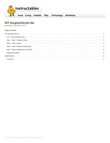
3x 4pin wire of 1 meter ( 6) (local 3D print shop, 123-3d.nl)Some 608 ball bearings ( 4) AliExpress1x Chinese Arduino UNO ( 2.50) AliExpress1x Old laptop / raspberry pi / your own laptop ( ?)Some M8 nuts, some M5 nuts and some screwsTotal: Around 140,Note that this does not yet include the milling device. I used a Dremel 8200 series to start, but will change to add my normal router to it, or make something like a DCspindle onto it.Step 2: The designAs explained in the introduction, my hardware design is based on the Arduino CNC instructable, that I found here. Since no exact dimensions etc. were given in thisinstructable, I made the design all by myself again in Autodesk's Fusion 360.I designed it to have a range of 70cm in y-direction, 40cm in x-direction and 10cm in ilt-DIY-CNC-Router-Arduino-Based-GRBL/
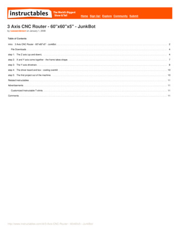
Step 3: The y-assemblyThe y-assembly is one of the easiest (and biggest) parts to make. I attached a building drawing, in which all dimensions are in mm's.Notes:Where 22-7 is written, this means that you need to drill a hole with a diameter of 22mm, and only 7mm's deep. This is for the bearings.Panel A-A and C-C are identical.Panel B-B and D-D are almost identical: In panel B-B you need to drill 1 22mm hole for the coupler nut between the stepper motor and the threaded rod. In panelD-D you don't drill this hole.The 12mm holes in panels B-B and D-D are only 9 mm deep.Before screwing the 80mm and 70mm pieces together, attach the first NEMA17 42BYGHW811 stepper motor to panel B-B. Then, attach the coupling nut and thethreaded rod (cut it to 750mm) to the stepper motor. Now you can screw the 70mm and 80mm pieces together but don't attach the large board yet. Otherwise we won'tbe able to attach the x-assembly. You'll end up with something that looks like figure C-Router-Arduino-Based-GRBL/
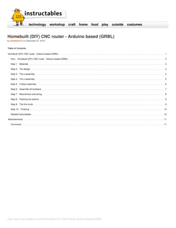
Step 4: The x-assemblyThe x-assembly contains some 3d printed parts. You can find these all on Thingiverse. For the x-assembly, you'll need:4x XY-joint2x Y-nut-holderYou can also make these parts from wood, but then you'll have to be a bit more creative yourself. :)Saw the wood as shown in drawing, but don't screw all parts together before the Z-Block is finished (next step).Note: In the left side panel, the 22mm hole is only 7mm deep (bearing) and the 10mm hole goes through. In the right panel, the 22mm hole goes through (because of thecoupler -CNC-Router-Arduino-Based-GRBL/
Step 5: Z-block assemblyOne of the most difficult part is the Z-block. Drilling of the holes has to be very precise, otherwise the friction will be too high, since the steel rods won't be perfectlyaligned with the holes in the side panels of the x-assembly. My tip is to use a mitre saw to cut the wood and a column drill to drill the holes!In the 3D render, the nut-holder is placed on the outside. To reduce space, I mounted it on the inside in my real design. In the photo taken, you can also see the nylonbearings.The vertical sliding black parts on the images, are 3D printed as well, and can be found on the thingiverse page of the previous step. Same for the motor mount.The wood needs to be sawn and drilled as shown in figure C-Router-Arduino-Based-GRBL/
Step 6: Assemble all hardwareNow start assembling all parts. Begin with the Z parts, then connect them to the X-frame (see the first image). Then attach the bottom part of the x assembly and attachall to the Y-axises. The 3D printed Y-Nut, X-Nut and Z-Block parts have space for a nut that goes over the threaded rods. Use these!Now, make sure that you can move each axis by turning the threaded rod by hand. If this is very difficult, you alignment if probably wrong, causing a lot of friction.Reassemble and realign until this is all good!In the end, you should end up with the full assembly as shown in the second Y-CNC-Router-Arduino-Based-GRBL/
Step 7: Motordrivers and wiringWith the motor drivers I used, the wiring should be as shown in figure 1. The ground on the left of the image, is the ground from the arduino (not from the 12v powersupply).The Phase A and Phase B can be found using a simple multimeter: The resistance over a phase (A and A- for example) is zero. For the wiring, it doesn't matter whichone is A or A-, as long as the resistance between both A wires, is zero. Same for the B phase.The switches on the motor driver are not really clear to me yet, but with S3 and S4 switched in this way, the step size will be 1/8 of the normal step size, resulting is muchmore gentle and precise steps.The wiring on the Arduino is as explained in the grbl wiki on Github. For the minimum basics, we only have to wire digital pins 2-7 and GND to the stepper driver IY-CNC-Router-Arduino-Based-GRBL/
Step 8: Flashing the arduinoDownload and extract GRBL from Github and open the Arduino IDE. Via Sketch - Include Library - Add zip library select the 'grbl' directory from the just extractedfolder. Restart the arduino IDE and under file - Examples, there should now be a grbl example, named grblUpload. Open it and upload it to the Arduino.Now open the Serial monitor (under Tools) and set baudrate to 115000.You should now get the message 'Grbl 0.9j [' ' for help]'So enter and hit return. Now enter and hit return. There you should see all the current settings for your grbl, which should be as default. Now, you can changeeverything you need. Details are explained on the grbl Github. My settings are as attached, but if your axis move in the wrong direction (because you might have B- andB different for example), you should switch these.Step 9: The first circleNow, when the building and the flashing is done, it's time to do something! Download the Universal G-Code Sender here (info on Github, here) and connect to yourArduino with a baudrate of 115200 again.Now power up your power supply and go to 'Machine Control'. You should now be able to move your machine using the controls on this display!!Hook up a pen to your z-axis, and save this text (using notepad) as circle.gcode:G17 G20 G90 G94 G54G0 Z0.25X-0.5 Y0.Z0.1G01 Z0. F5.G02 X0. Y0.5 I0.5 J0. F2.5X0.5 Y0. I0. J-0.5X0. Y-0.5 I-0.5 J0.X-0.5 Y0. I0. J0.5G01 Z0.1 F5.G00 X0. Y0. Z0.25When you go to the File Mode tab in the Universal G Code Sender, you open circle.gcode and as soon as you click Send, your machine should now start painting acircles with a diameter of exact 2 IY-CNC-Router-Arduino-Based-GRBL/
Step 10: FinishingAs soon as you know your machine is working, it's time to hook up your router of dremel to start milling! Because every router is different from others, you have to be a bitcreative yourself. But when you have come this far, I'm sure you'll get your router attached!Good luck!If you liked this instructable, please vote for me in the Arduino Contest. :)Related InstructablesArduino CNC byJohnnieTCNC machinefor shapinglarge pieces ofpolystyrenefoam byRTegelbeckers 400 DIY DrawerSlide CNCMachine (video) 3020 CNC Arduino GRBLby stangtime CNC Shield V3by EricAusomecnc Grbl withAdafruit MototShield v2 t-DIY-CNC-Router-Arduino-Based-GRBL/GRBL PinoutArduino Nanov3.0 by drluffy
/id/Homebuilt-DIY-CNC-Router-Arduino-Based-GRBL/
Intro: Homebuilt (DIY) CNC router - Arduino based (GRBL) Already for a few months or even years, I was planning to build my own CNC milling machine. Now I decided it was time to do it! I read a lot about other DIY projects and in the end I liked the design from the Ardu