Transcription
Power Transformer ProtectionPower Transformer ProtectionByVelimir Lackovic, Electrical EngineerPDHLibrary Course No 020170505 PDH HOURS
Power Transformer ProtectionThe advancement of electrical power systems has been reflected in the developmentsin power transformer manufacturing. This has led to a wide range of powertransformers. Their ratings range from a few kVA to several hundred MVA and areused for a wide variety of applications. Power transformer protection varies with theapplication and transformer importance. In the case of a fault within the powertransformer it is important to minimize tripping time in order to decrease the impact ofthermal stress and electrodynamic forces. Distribution power transformers can beprotected by using fuses or overcurrent protection relays. This leads to time-delayedprotection due to downstream co-ordination requirements. Nevertheless, time delayedshort circuit clearance is unacceptable on larger power transformers due to systemoperation/stability and cost of repair.Power transformer short circuits are typically grouped into five categories:-Winding and terminal short circuits-Core short circuits-Tank and transformer accessory short circuits-On–load tap changer short circuits-Prolonged or uncleared external short circuitsSummary of short circuit causes initiated in the power transformer itself, is shown inFigure 1.Winding and TerminalCoreTank and AccessoriesOLTCFigure 1. Power transformer short circuit statisticsPower Transformer Protection www.pdhlibrary.com2
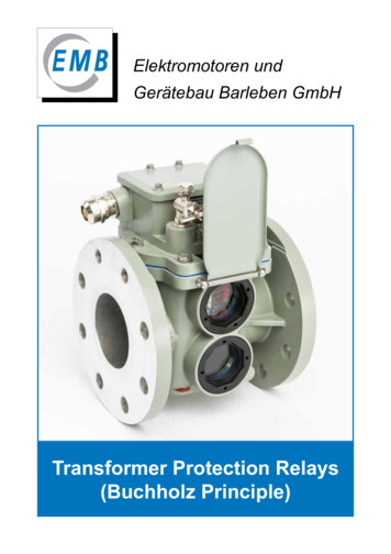
TRANSFORMER WINDING FAULTSA transformer winding fault is limited in magnitude by the following factors:-source impedance-neutral grounding impedance-winding connection arrangement-fault voltage-power transformer leakage reactanceFew distinct cases come up and are described OINTGROUNDED THROUGH AN IMPEDANCEThe winding ground fault current depends on the grounding impedance value and isalso directly proportional to the distance of the fault from the transformer neutral point,since the fault voltage will be directly proportional to this distance. For a fault on atransformer secondary winding, the matching primary current will depend on thetransformation ratio between the primary winding and the short-circuited secondaryturns. This also changes with fault position, so that the fault current in the transformerprimary winding is directly proportional to the square of the fraction of the winding thatis short-circuited. The case is presented in Figure 2. Faults in the lower third of thetransformer winding generate very little current in the primary winding and that makesfault detection by primary current measurement challenging.Power Transformer Protection www.pdhlibrary.com3
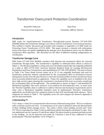
Percentage of respective maximumsingle phase earth fault 0Distance of fault from neutral (percentage of winding)Fault CurrentPrimary CurrentIPIFFigure 2. Ground fault current in resistance grounded star windingSTAR-CONNECTED WINDING WITH NEUTRAL POINT SOLIDLY GROUNDEDThe fault current is limited by the leakage reactance of the transformer winding, whichchanges in a complex pattern with the fault position. The variable fault point voltage isalso a critical factor, as in the case of impedance grounding. For faults close to theneutral end of the transformer winding, the reactance is very low, and results in thegreatest fault currents. The variation of current with fault location is presented in Figure3.Power Transformer Protection www.pdhlibrary.com4
Current (per unit)151050020406080Distance of fault from neutral (percentage of winding)Primary Current100Fault CurrentFigure 3. Ground fault current in solidly grounded star windingFor transformer secondary winding faults, the primary winding fault current is found bythe variable transformation ratio. Since the secondary fault current magnitude remainshigh throughout the winding, the primary fault current is significant for most pointsalong the transformer winding.DELTA-CONNECTED TRANSFORMER WINDINGDelta-connected winding elements do not operate with a voltage to earth of less than50% of the phase voltage. Hence, the range of fault current magnitude is less than fora star winding. The real figure of fault current will still depend on the system grounding.It has to be noted that the impedance of a transformer delta winding is especially highto fault currents running to a centrally placed fault on one leg. It can be expected thatthe impedance is between 25% and 50%, depending on the power transformer rating,regardless of the normal balanced through-current impedance. Since the prefaultvoltage to ground at this point is half the normal phase voltage, the ground fault currentmay be no more than the rated current, or even less than this figure if the source orsystem grounding impedance is appreciable. The current will run to the fault locationfrom each side through the two half windings, and will be split between two phases ofthe system. Hence, the individual phase currents may be relatively low which cancause difficulties in providing protection.Power Transformer Protection www.pdhlibrary.com5
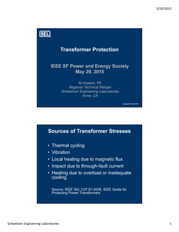
PHASE TO PHASE TRANSFORMER FAULTSFaults between phases within a transformer are relatively uncommon. However, in thecase such fault happens, it will give rise to a significant current comparable to theground fault currents.INTERTURN TRANSFORMER FAULTSIn low voltage transformers, interturn insulation breakdown is unlikely to happenunless the mechanical force on the winding due to external short circuits has causedinsulation degradation, or insulating oil (if used) has become contaminated bymoisture. A high voltage power transformer connected to an overhead transmissionline will be exposed to steep fronted impulse voltages, developing from lightningstrikes, network faults and switching processes. A line surge, which may be of fewtimes the nominal system voltage, will concentrate on the transformer winding endturns because of the high equivalent frequency of the surge front. Part-windingresonance, involving voltages up to 20 times nominal voltage may happen. Theinterturn insulation of the winding end turns is strengthened, but cannot be enhancedin proportion to the insulation to ground, which is relatively high. Therefore, partialwinding flashover is more likely. The consequent progress of the fault, if not discoveredin the earliest stage, may well destruct the evidence of the real cause.A short circuit of a few turns of the transformer winding will give rise to a big faultcurrent in the short-circuited loop. However, the terminal currents will be very small,because of the high ratio of transformation between the whole winding and the shortcircuited turns.The graph in Figure 4 presents the relevant information for a typical transformer of3.25% impedance with the short circuited turns symmetrically placed in the windingcenter.TRANSFORMER CORE FAULTSA conducting bridge across the laminated structures of the transformer core can allowsufficient eddy-currents which can cause serious overheating. The bolts that clampthe core together are always insulated to prevent this problem. If any part of the corePower Transformer Protection www.pdhlibrary.com6
insulation becomes faulty, the resultant heating may attain a magnitude sufficient to100108086064042020Primary current (multiples rated current)Fault current (multiples of rated current)damage the winding.005101520Turns short-circuited (percentage of winding)Fault current in short circuited turns25Primary input currentFigure 4. Interturn fault current/number of short-circuited turnsEven though additional core loss causes serious local heating, it does not generate adetectable change in input current and could not be discovered by the typical electricalprotection. Nevertheless it is crucial that the situation is discovered before a significantfault has been created. In an oil-immersed power transformer, core heating highenough to cause winding insulation damage also causes oil breakdown with anaccompanying evolution of gas. This gas flows to the conservator and is used to runa mechanical relay.TRANSFORMER TANK FAULTSLoss of oil through transformer tank leaks eventually creates a dangerous situation,either because of a reduction in winding insulation or because of. Overheating mayalso happen due to sustained overload, blocked cooling ducts or failure of the forcedcooling mechanism.Power Transformer Protection www.pdhlibrary.com7
EXTERNALLY APPLIED CONSIDERATIONSCauses of abnormal stress in a power transformer are:-overload-system short circuits-overvoltage-reduced system frequencyOVERLOADOverload creates increased 'copper loss' and a subsequent temperature increase.Overloads can be tolerated for limited periods and suggestions for oil-immersed powertransformers are provided in IEC 60354.The transformer thermal time constant of naturally cooled power transformers liesbetween 2.5-5 hours. Shorter time constants are applicable for the force-cooled powertransformers.SYSTEM SHORT CIRCUITSSystem faults generate a relatively intense heating rate of the feeding transformerswhile the copper loss increases in proportion to the square of the per unit short circuitcurrent. The common external short circuits duration that power transformer cansustain without damage if the fault current is limited only by the self-reactance ispresented in Table 1. IEC 60076 gives additional instructions on short-circuit withstandlevels.Transformer Short circuit currentAllowable faultreactance (%) (Multiple of rating) duration (seconds)42525202616.62714.22Table 1. Power transformer short circuit current withstand informationMaximum mechanical stress on transformer windings happens during the first cycle ofthe fault. Avoidance of damage is a matter of power transformer design.Power Transformer Protection www.pdhlibrary.com8
OVERVOLTAGESOvervoltage situations are of two kinds:-transient surge voltages-power frequency overvoltageTransient overvoltages develop from faults, switching, and lightning disturbances.They are liable to cause interturn faults. These overvoltages are typically fixed byshunting the high voltage terminals to ground either with a plain rod gap or by surgediverters, which constitute a stack of short gaps in series with a non-linear resistor.The surge diverter, in contrast to the rod gap, has the advantage of eliminating theflow of power current after discharging a surge. In this way it prevents subsequenttransformer isolation.Power frequency overvoltage causes both an increase in insulation stress and aproportionate working flux increase. The second effect increases both the iron lossand magnetising current. In addition, flux is diverted from the laminated core intostructural steel elements. The core bolts, which typically carry little flux, may beexposed to a high flux diverted from the greatly saturated region of core alongside.This ends in a rapid temperature rise in the bolts, damaging their and coil insulation.REDUCED SYSTEM FREQUENCYSystem frequency reduction affects flux density. Transformer can function with somedegree of overvoltage with a matching increase in frequency, but transformer servicemust not be extended with a high voltage input at a low frequency. Service cannot bemaintained when the ratio of voltage to frequency, with these quantities expressed inper unit of their rated values, exceeds unity by more than a small number, for exampleif V/f 1.1. If a significant increase in system voltage has been taken care of in thetransformer design stage, the base of 'unit voltage' should be taken as the greatestvoltage for which the power transformer is designed.TRANSFORMER MAGNETISING INRUSHThe process of magnetising inrush is a transient condition that primarily happens whena power transformer is energised. It is not a fault condition, and hence transformerPower Transformer Protection www.pdhlibrary.com9
protection must stay stable during the inrush transient. Figure 5(a) presents a powertransformer magnetizing characteristic. To minimize costs, weight and size, powertransformers are typically operated near to the ‘knee point’ of the magnetising curve.Accordingly, only a small raise in core flux above normal working levels will end in agreat magnetising current. Under normal steady-state conditions, the magnetisingcurrent related with the operating flux level is relatively small, as presented in Figure5(b). Nevertheless, if a power transformer winding is energized at a voltage zero, withno remanent flux, the flux level during the first voltage cycle (2 x normal flux) will endin core saturation and a great non-sinusoidal magnetizing current waveform, aspresented in Figure 5(c). This current is known as magnetising inrush current and mayremain for few cycles. Few factors impact the magnitude and magnetising currentinrush duration:-point on wave switching-residual flux – worst-case conditions end in the flux peak value achieving 280%of normal value-number of banked power transformers-transformer design and rating-system short circuit current levelThe big flux densities mentioned above are so far beyond the normal working rangethat the incremental relative permeability of the core approximates to unity and theinductance of the transformer winding falls to a figure near that of the 'aircored'inductance. The current wave, starting from zero, increases slowly at first. The fluxhas a value just above the residual value and the permeability of the core being fairlybig. As the flux passes the normal working value and enters the greatly saturatedportion of the magnetizing curve, the inductance decreases and the current quicklyrises to a peak that may be 500% of the steady state magnetizing current.Power Transformer Protection www.pdhlibrary.com10
FluxNormal peakfluxMagnetisingcurrentVoltage and fluxTransient flux 80%residual at switchingTransient flux noresidual at switchingSteady-state fluxVoltageTimeSlow decrementZeroaxisZeroaxisFigure 5. Power transformer magnetizing inrush (a) Common magnetizingcharacteristic (b) Steady and maximum offset fluxes (c) Common inrush current (d)Inrush without offset, due to yoke saturationWhen the peak is passed at the next voltage zero, the next negative half cycle of thevoltage wave decreases the flux to the starting value and the current symmetricallydrops to zero. Hence, the current wave is totally offset and is only restored to thesteady state condition by the circuit losses. The transient time constant has a rangebetween 0.1 second (for a 100kVA power transformer) to 1.0 second (for a large powertransformer). As the magnetising characteristic is non-linear, the envelope of thePower Transformer Protection www.pdhlibrary.com11
transient current is not purely of exponential form. It can be noted that the magnetisingcurrent changes up to 30 minutes after switching on. Even though right choice of thepoint on the wave for a single– phase power transformer will result in no transientinrush, mutual effects ensure that a transient inrush happens in all phases for threephase power transformers.INRUSH WAVEFORM HARMONIC CONTENTThe power transformer magnetising current waveform contains a proportion ofharmonics that increments as the peak flux density is raised to the saturating condition.The transformer magnetising current contains a third harmonic and increasinglysmaller amounts of fifth and higher harmonics. If the saturation degree is progressivelyincreased, not only will the harmonic content increment as a whole, but the relativeproportion of fifth harmonic will increase and finally outmatch the third harmonic. At ahigher level the seventh would overcome the fifth harmonic but this needs a degree ofsaturation that will not be experienced with power transformers.The energising conditions that end in an offset inrush current create a waveform thatis asymmetrical. Such a wave commonly comprises both even and odd harmonics.Common inrush currents contain significant amounts of second and third harmonicsand diminishing amounts of higher orders. As with the steady state wave, theproportion of harmonics changes with the saturation degree, so that as a dangerousinrush transient decays, the harmonic makeup of the current goes through a range ofconditions.POWER TRANSFORMER OVERHEATINGThe power transformer rating is based on the temperature increase above an assumedmaximum ambient temperature. Sustained overload is not typically allowable underthis condition. Certain degree of sustained overload can be tolerated at a lowerambient temperature. Short-term overloads are also allowable to an extent dependenton the previous loading conditions. IEC 60354 standard gives assistance in thisrespect. The only true statement is that the transformer winding must not overheat.Temperature of about 95 C is conceived as the normal maximum working valuebeyond which an additional increase of 8 - 10 C, if maintained, will halve thePower Transformer Protection www.pdhlibrary.com12
transformer insulation life. Hence, overload protection is based on windingtemperature, which is typically measured by a thermal image technique. Protection isset to trip the power transformer if excessive temperature is achieved. The trip signalis typically routed via a digital input of a protection relay on one side of the powertransformer, with both alarm and trip facilities made available through programmablelogic in the protection relay. Intertripping between protection relays on the two sidesof the power transformer is typically used to ensure total disconnection of thetransformer. Winding temperature protection may be part of a overall monitoringpackage.OVERVIEW OF THE POWER TRANSFORMER PROTECTIONThe issues relating to power transformers presented in previous sections require somemeans of protection. Table 2 presents the problems and the potential protection formsthat may be applied. The next sections give more details on the individual protectionmethods. It is typical for a modern protection relay to provide all of the neededprotection functions in a single package. Electromechanical technology would involveseveral protection relays with interconnections and higher overall CT burdens.Fault typeSecondary winding phase-ground faultInterturn faultCore faultTank faultOverheatingPrimary winding phase-phase faultPrimary winding phase-ground faultSecondary winding phase-phase faultOverfluxingProtection usedDifferential, Restricted ground faultDifferential, BuchholzDifferential, BuchholzDifferential, Buchholz, Tank-groundThermalDifferential, OvercurrentDifferential, OvercurrentDifferentialOverfluxingTable 2. Power transformer fault types/protection arrangementsTRANSFORMER OVERCURRENT PROTECTIONFuses may adequately protect small power transformers, but larger ones needovercurrent protection using a protection relay and circuit breaker, as fuses do nothave the needed fault breaking capacity.Power Transformer Protection www.pdhlibrary.com13
FUSESFuses typically protect small distribution transformers up to ratings of 1MVA atdistribution voltages. In many situations no circuit breaker is provided, making fuseprotection the only available way of automatic isolation. The fuse must have a ratingwell above the maximum power transformer load current to resist the short durationoverloads that may happen. Also, the fuses must resist the magnetising inrushcurrents taken when power transformers are energised. High Rupturing Capacity(HRC) fuses, even though very fast in operation with huge fault currents, are superslow with currents of less than three times their nominal value. Such fuses will do littleto protect the power transformer, serving only to protect the system by disconnectinga faulty power transformer after the fault has reached an advanced stage. Table 3presents common ratings of fuses for use with 11kV power transformers.Transformer RatingFusekVAFull loadNominal Operating time atcurrent (A) current (A)3 x Rating 0.0100052.59030.0Table 3. Common fuse ratings for application with distribution transformersAbove table should be taken only as a common example. Significant differences existin the time curves of different types of HRC fuses. Moreover, grading with secondaryside protection has not been looked at.OVERCURRENT PROTECTION RELAYSWith the arrival of ring main units comprising SF6 circuit breakers and isolators,protection of distribution transformers can now be achieved by overcurrent trips or byprotection relays connected to current transformers connected on the transformerprimary side. Overcurrent protection relays are also used on bigger transformersequipped with standard circuit breaker control. Improvement in relay protection isachieved in two ways; the great delays of the HRC fuse for lower fault currents arePower Transformer Protection www.pdhlibrary.com14
averted and ground-fault tripping element is provided in addition to the overcurrentelement. The time delay curve should be selected to discriminate with circuit protectionon the transformer secondary side. A high-set instantaneous protection relay elementis typically provided, the current setting being selected to avoid operation for asecondary short circuit. This allows high-speed clearance of primary terminal shortcircuits.RESTRICTED EARTH FAULT PROTECTIONConventional ground fault protection using overcurrent devices fails to give properprotection for power transformer windings. This is especially true for a star-connectedwinding with an impedance-grounded neutral. The protection degree is considerablyimproved by the usage of restricted earth fault protection (or REF protection). This isa unit protection arrangement for one winding of the transformer. It can be a highimpedance type as presented in Figure 6 or a biased low-impedance type. For thehigh impedance arrangement, the residual current of three line current transformers isbalanced against the output of a current transformer in the neutral conductor. In thebiased low impedance arrangement, the three line currents and the neutral currentbecome the bias inputs to a differential device. The system is functional for faults withinthe region between current transformers, that is, for faults on the star winding. Thesystem stays stable for all faults outside this protection zone.I High impedance relayFigure 6. Star winding restricted earth fault protectionImprovement in protection performance comes not only from using an instantaneousprotection relay with a low setting, but also because the total short circuit current isPower Transformer Protection www.pdhlibrary.com15
measured, not only the transformed component in the transformer HV primary winding(if the star winding is a secondary winding). Restricted earth fault protection is usuallyused even when the neutral is solidly grounded. Since short circuit current then staysat a high value even to the last turn of the transformer winding, nearly complete coverfor ground faults is achieved. This is an improvement in comparison with theperformance of systems that do not measure the neutral conductor current.Ground fault protection use for delta-connected or ungrounded star winding isinherently restricted, since no zero sequence components can be transferred throughthe transformer to the other windings. Both transformer windings can be separatelyprotected with restricted earth fault protection. This arrangement provides high speedprotection against ground faults for the complete transformer with relatively simpleequipment. A high impedance relay is applied, allowing fast operation and phase faultstability.TRANSFORMER DIFFERENTIAL PROTECTIONThe restricted earth fault arrangement completely depends on the Kirchhoff principlethat the sum of the currents running into a conducting network is zero. A differentialsystem can be organized to protect the complete transformer. This is possible due totransformer high efficiency operation, and the similar equivalence of ampere turnsgenerated on the primary and secondary windings. Figure 7 presents the principle.Current transformers on the primary and secondary sides are connected to form acirculating current system.I d Figure 7. Transformer differential protection principlePower Transformer Protection www.pdhlibrary.com16
TRANSFORMER DIFFERENTIAL PROTECTION BASIC CONSIDERATIONSA variety of considerations have to be kept in mind when applying the principles ofdifferential protection to power transformers. These considerations include:-the possible occurrence of overfluxing-the impacts of the variety of grounding and winding arrangements (filtering ofzero sequence currents)-correction for potential phase shift across the transformer windings (phasecorrection)-the impact of magnetising inrush during initial start-correction for potential unbalance of signals from current transformers on eitherside of the transformer windings (ratio correction)In traditional transformer differential arrangements, the demands for phase and ratiocorrection were met by the application of external interposing current transformers(ICTs) or by a delta connection of the main CTs to give phase correction.Digital/numerical protection relays use ratio and phase correction. It is implementedthrough the software and enables most combinations of transformer winding schemes,irrespective of the winding connections of the primary CTs. It does not need theadditional space and cost requirements of hardware interposing CTs.LINE CURRENT TRANSFORMER PRIMARY RATINGSLine current transformers have primary ratings chosen to be about same as nominalcurrents of the transformer windings to which they are applied. Primary ratings willtypically be fixed to those of available standard ratio CTs.PHASE CORRECTIONTransformer differential protection correct operation requires that the powertransformer primary and secondary currents, as measured by the protection relay, arein phase. If the power transformer is delta/star connected, balanced three phasethrough current is phase shifted for 30 , as presented in Figure 8. If left uncorrected,this phase difference would lead to the protection relay seeing through current as anPower Transformer Protection www.pdhlibrary.com17
unbalanced fault current, and result in relay operation. Phase correction must beapplied.ABCId Id Id Figure 8. Differential protection for two-winding delta/star power transformerElectromechanical and static protection relays use adequate CT/ICT connections toassure that the primary and secondary currents transferred to the protection relay arein phase. For digital and numerical protection relays, it is typical to use star connectedline CTs on all transformer windings and compensate for the winding phase shift usingsoftware. Depending on protection relay design, the only information needed in suchcircumstances may be the transformer vector group. Phase compensation is thenautomatically completed. Caution is needed if such protection relay is used to replacean existing electromechanical or static relay since the primary and secondary line CTsmay not have the same winding arrangement. In such situations, phase compensationand related protection relay data entry needs more detailed consideration.Occasionally, the available phase compensation facilities cannot accommodate thepower transformer winding connection. Interposing CTs must be used in suchsituations.Power Transformer Protection www.pdhlibrary.com18
ZERO SEQUENCE CURRENT FILTERINGIt is important to provide some method of zero sequence filtering when a transformerwinding can pass zero sequence current to an external ground fault. This is to ensurethat out-of-zone ground faults are not detected by the power transformer protection asan in-zone fault. This is accomplished by use of delta-connected line CTs orinterposing CTs for older protection relays. The winding connection of the line and/orinterposing CTs must take this into consideration, in addition to any necessary phasecompensation. For digital/numerical protection relays, the required filtering is providedin the protection relay software. Table 4 presents the phase compensation and zerosequence filtering erPhase ShiftClockfacevectorPhasecompensationneeded0 0 0 Zy130 130 180 1180 30 1130 Zy11YzHZdHDyH(H/12)x360 Hour‘H’-(H/12)x360 HV ZeroSequenceFilteringYesYesLV sYesYesYesYesYesYesYesYesTable 4. Current transformer connection for power transformers of different vectorgroupsRATIO CORRECTIONCorrect service of the differential element demands that currents in the differentialelement balance under load and through fault conditions. As the primary andsecondary line CT ratios may not precisely match the power transformer rated windingcurrents, digital/numerical protection relays are provided with ratio correction factorsPower Transformer Protection www.pdhlibrary.com19
for each of the CT inputs. The correction factors may be automatically computed bythe protection relay from knowledge of the line CT ratios and the transformer MVArating. Nevertheless, if interposing CTs are applied, ratio correction may not be simpletask and may need to consider a factor of 3 if delta-connected CTs or ICTs areinvolved. If the power transformer is equipped with a tap changer, line CT ratios andcorrection factors are typically selected to reach current balance at the mid tap of thepower transformer. It is mandatory to ensure that current mismatch due to off-nominaltap service will not cause spurious operation.BIAS SETTINGBias is used for transformer differential protection for the same reasons as any unitprotection arrangement – to give stability for external faults while allowing sensitivesettings to pick up internal faults. Th
Power Transformer Protection www.pdhlibrary.com protection must stay stable during the inrush transient. Figure 5(a) presents a power transformer magnetizing characteristic. To minimize costs, weight and size, power transformers are typically op